Volumetric Data Fusion of External Depth and Onboard Proximity Data For Occluded Space Reduction
Abstract
In this work, we present a method for a probabilistic fusion of external depth and onboard proximity data to form a volumetric -D map of a robot’s environment. We extend the Octomap framework to update a representation of the area around the robot, dependent on each sensor’s optimal range of operation. Areas otherwise occluded from an external view are sensed with onboard sensors to construct a more comprehensive map of a robot’s nearby space. Our simulated results show that a more accurate map with less occlusions can be generated by fusing external depth and onboard proximity data.
4th Workshop on Proximity Perception
2021 IEEE/RSJ International Conference on Intelligent Robots and Systems (IROS 2021), Prague, Czech Republic
Published under the Creative Commons license (CC BY-NC-ND) at KITopen
I INTRODUCTION
Roboticists have begun to investigate robot capabilities in cluttered environments where obstacles can be occluded from view of external depth sensors. In order for robots to plan safe trajectories, the robot motion planner requires an accurate spatial depiction of the robot’s workspace. Traditionally, object positions surrounding the robot are estimated using depth data from externally mounted cameras, such as the Microsoft Kinect. However, the depth data provided from externally mounted cameras is prone to occlusions when objects are placed between the camera and the robot itself, as noted in [1]. Occlusions lead to an incomplete view of the robot’s workspace that make it difficult to plan safe paths. To gain information about areas otherwise occluded from external depth sensors, [1] highlighted the benefits of using distance sensors placed on the robot’s body.
Previous work using onboard proximity sensors has focused on utilizing information immediately for contact avoidance or anticipation, as shown in [2, 3]. External depth cameras have also been utilized for contact avoidance [4], and are frequently used to map a robot’s surrounding space. To add additionally utility to data measured by onboard proximity sensors, in this paper, we fuse external depth and onboard proximity data to create a volumetric representation of the robot’s environment. We extend the Octomap [5] framework to include onboard proximity sensor units along with external depth data. Our results demonstrate that otherwise occluded areas can be mapped using onboard proximity sensors.
II Multi-modal Octomap Generation
In our simulated environment, a depth camera is placed to give a third person view of the robot’s workspace, and proximity sensors are placed on the robot’s end-effector. We then process the information obtained from each sensor to compute the position of objects near the robot. Then, extending the Octomap framework, we modify our map using a novel probabilistic update, dependent on which sensor detected each object.
II-A Object Detection
II-A1 Onboard Proximity Sensors
We position each proximity sensor so that its distance measurement is aligned with the sensor’s -axis. Accordingly, the position of an object detected by sensor unit can be computed as:
| (1) |
where is the th proximity sensor, and is the position of with respect to the robot’s base frame . is the rotational matrix of with respect to the robot’s base frame. is the sensed distance from the sensor to the object.
II-A2 Depth Camera
The computation of an object’s position for a depth camera is given by:
| (2) |
where is the depth camera, and is the position of with respect to robot’s base frame. is the rotational matrix of with respect to the robot’s base frame. composes the -D position of a detected point in the sensor’s frame.
II-B Volumetric Mapping
Octomap is an occupancy grid mapping framework based on octrees, which generates a probabilistic occupancy estimation given noisy depth data [5]. It explicitly calculates occupied and free space probabilities. As sensor measurements are read, they are used to update the occupation probability of nodes within the octree. , the probability of node being occupied conditioned on , depends on the current measurement , a prior probability , and the previous probability estimate . We refer interested readers to Equation 1 in [5] for more information. To reduce computation time, Octomap uses the log-odds of to update a node’s occupation probability. The log-odds is expressed as:
| (3) |
The log-odds of node being occupied conditioned on sensors’ measurements from time to can be expressed as:
| (4) |
where is the prior log-odds and is the log-odds of a node conditioned on the current sensor measurement [5]. Furthermore, the probability of a node being occupied based on the current sensor data is expressed in log-odds terms as:
| (5) |
In our work, we modify the log-odds update notation to allow for multiple proximity sensors along with an external depth camera. Our log-odds update at time can then be written as:
| (6) |
where is the amount of onboard proximity sensors. is the log-odds of node given data from proximity sensor at time , and is the log-odds given data from depth camera . is computed as:
| (7) |
where is the distance from proximity sensor at time to a sensed object that is in node . If a beam (a ray of points connecting the sensor to the detected object) passes through a node, which means that there is no detected object in that specific node, then a negative log-odds update is received (here, corresponds to a probability of of node being occupied). is:
| (8) |
where is the distance from the depth camera to the sensed object.
For proximity data, we base our formulation on the official datasheet of the VL53L1X ToF sensor, which is the sensor we used in our previous real world experiments [3]. Its minimum range is cm. The ranging error for the VL53L1X ToF sensor in different test cases of varying distances is cm; the data sheet also shows that as the range of sensed data increases, so does the standard deviation of measurements [6]. With this information taken into account, we linearly decay the log-odds update value of proximity sensor data.
The depth camera log-odds value at a distance of m and below is (which does not change the probability of a node being occupied) because the operational range of the depth camera starts from m [7]. At distances greater than m, it has been shown that the ranging error (accuracy and precision) of ToF (Time-of-Flight) depth cameras slowly increases over time; hence we apply a linear decay on the log-odds value of a detected node from the depth camera [8]. We model our depth camera based on the Kinect-V2; its error is cm at m [8].
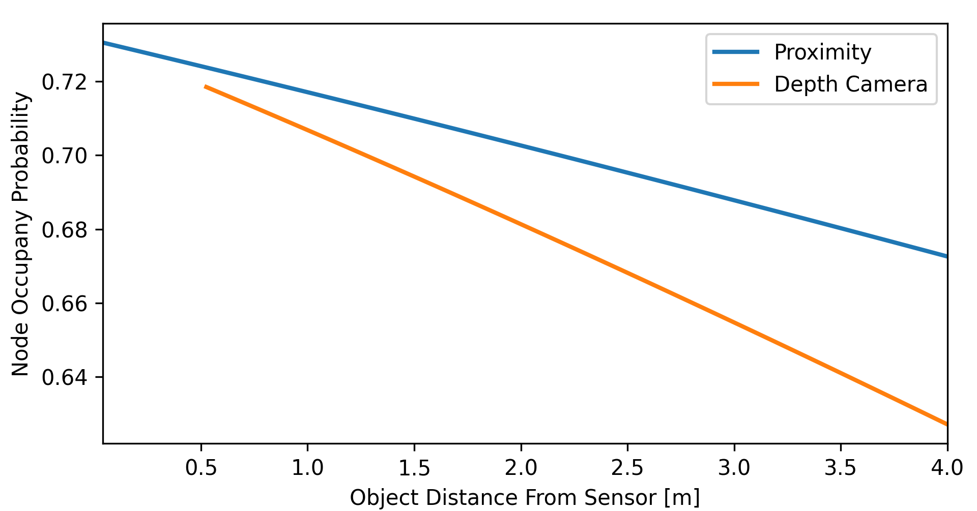
We graph the corresponding probabilities from our log-odds updates in fig. 2. The probability of a node being occupied with the depth camera from m to m decreases from to , and the occupation probability with a proximity sensor from m to m decreases from to . These values are centered around the optimal constant update value introduced in the original Octomap paper [5]. These values were set based on both sensor’s respective data sheets and research analysis of performance from [8, 7].
III Results
III-1 Setup
To evaluate our method, we conduct experiments in the Gazebo simulator using C++ and ROS with a simulated, 7-DoF Franka Emika Panda robotic manipulator. We simulate proximity sensors, placed on the robot end-effector, and an externally mounted depth camera. We publish batched proximity data at a rate of Hz with cm noise, while the depth camera data is published at a rate of Hz with cm noise. Noise is based on sensor error introduced in section II-B. Our results compare the amount of free and occupied space generated from proximity sensor data, depth camera data, and both data streams fused, as displayed in fig. 1 with a ground truth map. Our simulated environment is shown in fig. 1(a). During simulation, the robot moves in a circular path with a radius of m at a speed of m/s.
| Sensors Used | Occupied | Free | Missed | Incorrect |
|---|---|---|---|---|
| Depth Camera | 970 | 27510 | 3523 | 299 |
| Proximity | 587 | 47847 | 3697 | 26 |
| Proximity + Depth | 1430 | 66697 | 2469 | 317 |
III-A Volumetric Comparison
Our simulated environment can be seen in fig. 1(a) with two objects purposefully occluded by large shelves placed between the robot and the camera. The cone in fig. 1(a) is only sensed by the proximity sensors, as seen in fig. 1(c). The onboard proximity sensors’ information supplements the depth camera data to give a representation of the shelf as two distinct open compartments.
We compare our maps generated shown in fig. 1 to a ground truth mapping created with a manually controlled depth camera with no noise as shown in fig. 1(e) and fig. 1(f). In our evaluation, we compare the ground truth octree with a constructed octree, both of which have the same minimum octree resolution of m. From table I, the proximity and depth map has occupied nodes that matched the ground truth, as compared to for the depth camera and for proximity. The amount of correctly free nodes is also significantly higher for the proximity and depth map. Our method reduces the amount of missed occupied cells, while only slightly increasing the amount of incorrect nodes.
IV Conclusion
In this work, we introduced an adaptation of the Octomap framework that fuses external depth and proximity sensor data for probabilistic, volumetric map generation. Our results show that fusing both data streams into a cohesive map represents the environment in more detail then either independently. With respect to future work, we aim to implement this method on a real robot with real sensors, which we have worked with in the past for contact anticipation and avoidance [3]. Lastly, we plan to expand our simulation to accurately represent the VL53L1X ToF proximity sensor which has a viewing angle of approximately 27° in a cone shape. As objects are sensed further away form a given sensor, the uncertainly in object position increases, because multiple objects of different depth can be sensed from the same sensor position. These specific sensor characteristics must be addressed in order to generate an accurate map of a robot’s environment in real life.
References
- [1] S. E. Navarro, S. Mühlbacher-Karrer, H. Alagi, H. Zangl, K. Koyama, B. Hein, C. Duriez, and J. Smith, “Proximity perception in human-centered robotics: A survey on sensing systems and applications,” IEEE Transactions on Robotics, 2021.
- [2] Y. Ding and U. Thomas, “Improving safety and accuracy of impedance controlled robot manipulators with proximity perception and proactive impact reactions,” in 2021 IEEE International Conference on Robotics and Automation (ICRA). IEEE, 2021.
- [3] C. Escobedo, M. Strong, M. West, A. Aramburu, and A. Roncone, “Contact anticipation for physical human–robot interaction with robotic manipulators using onboard proximity sensors,” in IEEE/RSJ International Conference on Intelligent Robots and Systems (IROS), 2021.
- [4] F. Flacco, T. Kröger, A. De Luca, and O. Khatib, “A depth space approach to human-robot collision avoidance,” in 2012 IEEE International Conference on Robotics and Automation. IEEE, 2012.
- [5] A. Hornung, K. M. Wurm, M. Bennewitz, C. Stachniss, and W. Burgard, “Octomap: An efficient probabilistic 3d mapping framework based on octrees,” Autonomous robots, vol. 34, no. 3, pp. 189–206, 2013.
- [6] A new generation, long distance ranging Time-of-Flight sensor based on ST’s FlightSense™ technology, STmicroelectronics, 11 2018, rev. 3.
- [7] M. Tölgyessy, M. Dekan, L. Chovanec, and P. Hubinskỳ, “Evaluation of the azure kinect and its comparison to kinect v1 and kinect v2,” Sensors, vol. 21, no. 2, p. 413, 2021.
- [8] Y. He, B. Liang, Y. Zou, J. He, and J. Yang, “Depth errors analysis and correction for time-of-flight (tof) cameras,” Sensors, vol. 17, no. 1, p. 92, 2017.