Soft Lattice Modules that Behave Independently and Collectively
Abstract
Natural systems integrate the work of many sub-units (cells) toward a large-scale unified goal (morphological and behavioral), which can counteract the effects of unexpected experiences, damage, or simply changes in tasks demands. In this paper, we exploit the opportunities presented by soft, modular, and tensegrity robots to introduce soft lattice modules that parallel the sub-units seen in biological systems. The soft lattice modules are comprised of 3D printed plastic “skeletons”, linear contracting shape memory alloy spring actuators, and permanent magnets that enable adhesion between modules. The soft lattice modules are capable of independent locomotion, and can also join with other modules to achieve collective, self-assembled, larger scale tasks such as collective locomotion and moving an object across the surface of the lattice assembly. This work represents a preliminary step toward soft modular systems capable of independent and collective behaviors, and provide a platform for future studies on distributed control.
I Introduction
This paper presents soft modules that can attach to one another to form larger, more capable lattices. Different shapes of lattice assemblies support different tasks, and we demonstrate configurations performing locomotion, peristaltic surface manipulation and prehensile gripping.
We are particularly interested in exploring the intersection of work on soft robots and modular robots. While modular robot systems collectively reconfigure themselves to allow manipulation or locomotion, flexible lattices allow deformation as well as reconfiguration, motivating the exploration of new behaviors; for example, in this paper, we explore whole-body manipulation of a ball along the surface of the lattice. Eventually, we imagine that such a system could be used as a rapidly deployable, flexible structure with applications in disaster relief and construction, capable of serving as a 2D conveyance for materials or as active scaffolding for construction in hostile environments.
Soft robots constructed of flexible materials offer the possibility of simple mechanical designs, safe operation in the presence of humans and delicate objects, excellent resistance to mechanical impact, and compliance to adapt to uneven terrain [11]. Owing to high force-to-mass ratio, high work density, and the capability of being actuated by light on-board electronics [9], many soft robots are actuated using spring-memory alloy (SMA) variable length tendons [11], which can be combined with a flexible body to enable limb-like bending.
Collective behavior to perform complex tasks has garnered interest in recent years [37]. One thrust of prior research has been on small rigid-bodied units capable of rearranging into various chains or circular configurations in order to achieve novel locomotive capabilities [19, 21, 24]. Another thrust has been self-assembly and reconfiguration of lattice-based systems, in which robot modules are connected in a grid-like pattern [24].
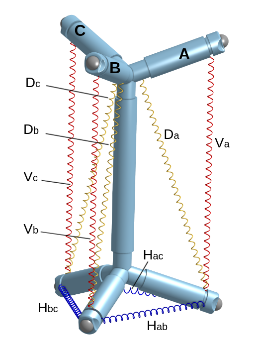
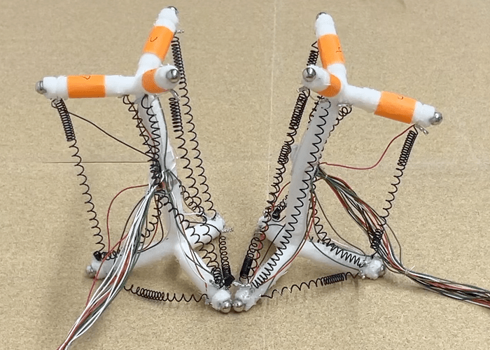
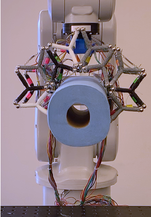
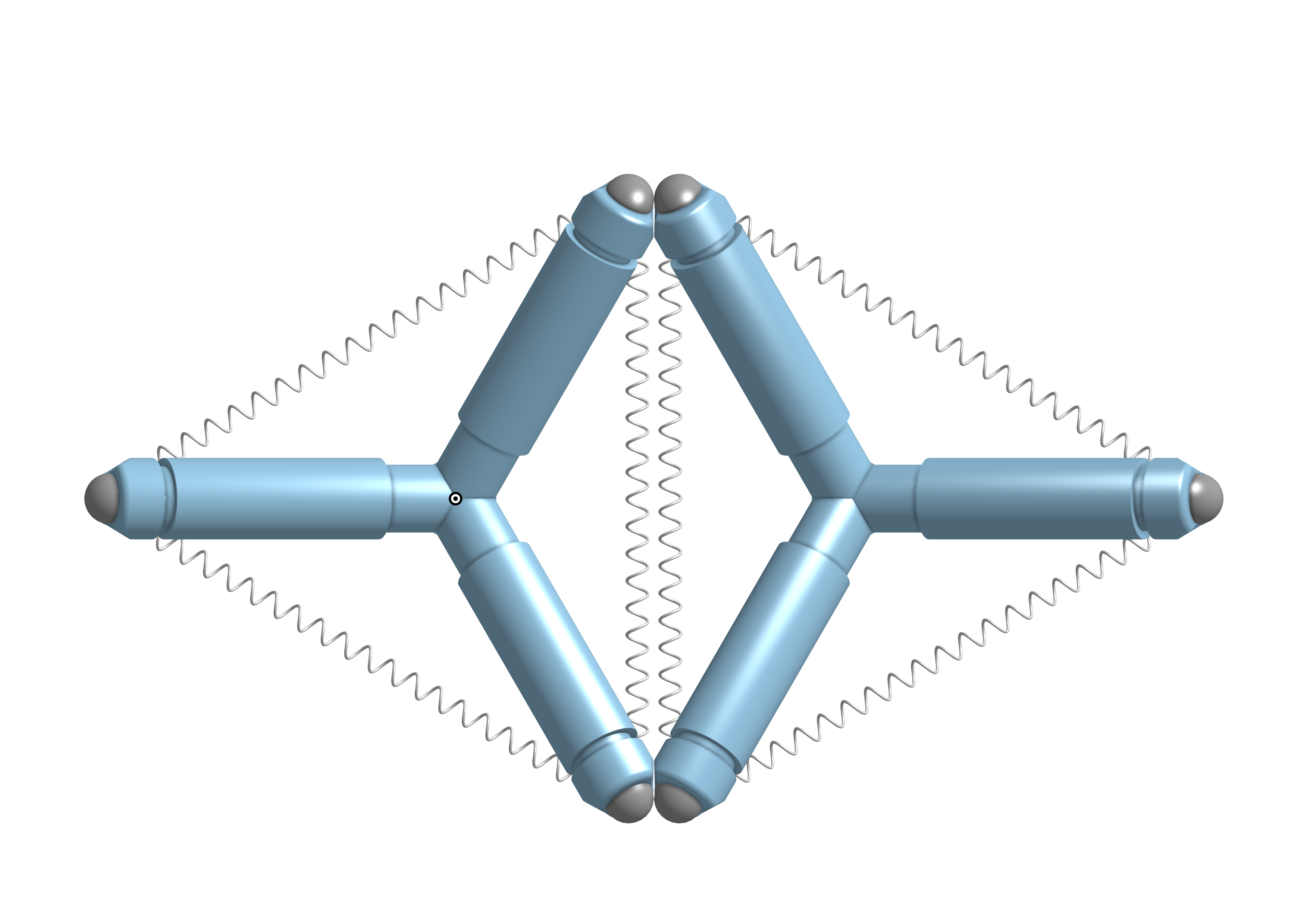
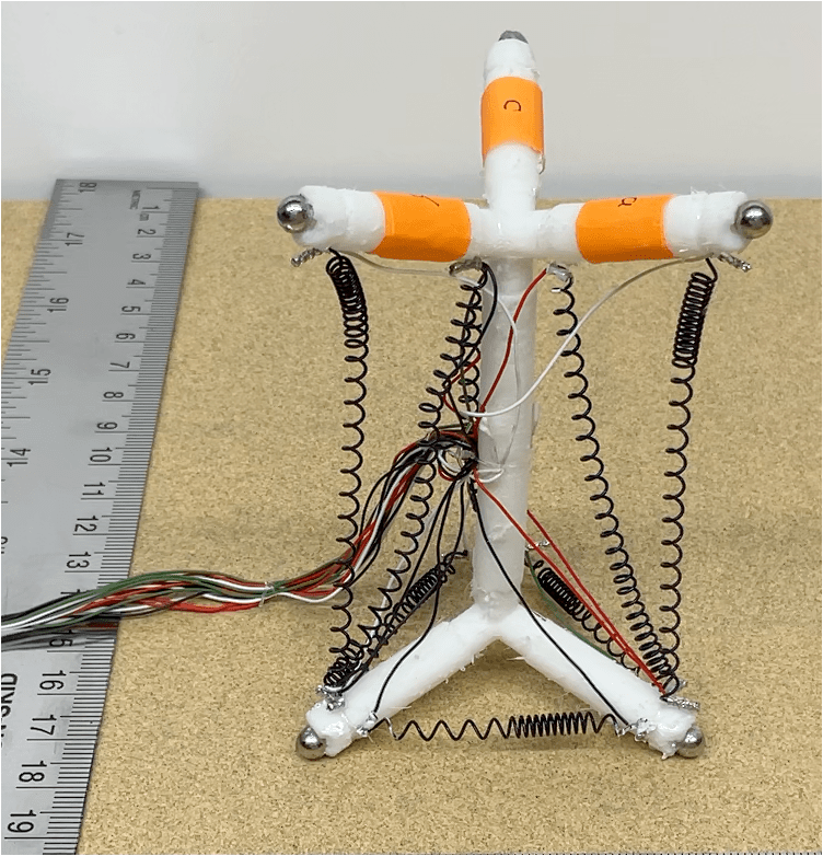
The modules in this paper are composed of 3D printed skeleton using a flexible Thermoplastic Polyurethane (TPU) material, shaped like a pair of stacked tetrahedrons (Fig. 1(a)), and SMA coils which are tethered to an Arduino located externally. SMAs are selected as actuators of this modular system due to their high force-to-mass ratio and high work density. The modules attach together via specially arranged magnets located at the end of the module arms.
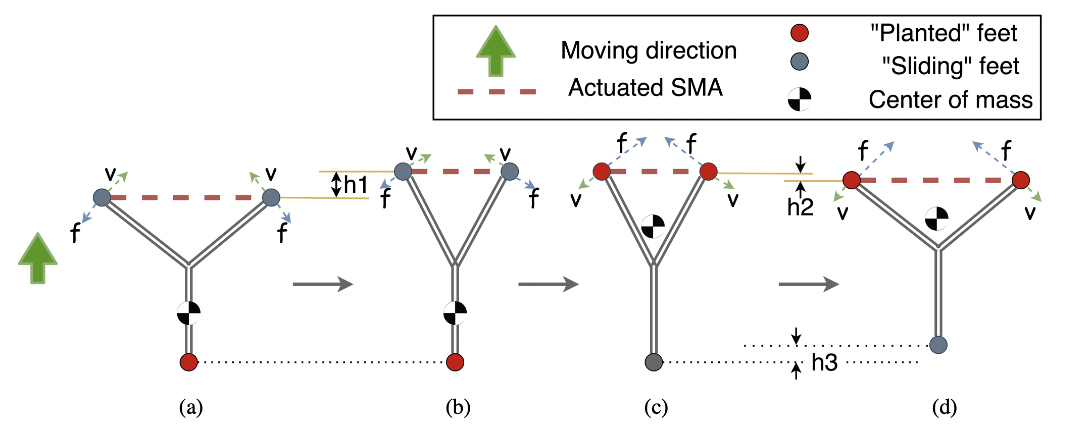
We designed two methods of locomotion for the individual module based off the principle of shifting the center of mass to change the relative friction of the bottom three feet as they slide along a surface. Once individual modules approach each other, they engage in an attachment protocol that helps ensure all four contact points are connected (Fig. 1(b)). We also developed a walking gait for locomotion of three-module units that is used to assemble a larger lattice (Fig. 1(c)). Once the lattice is assembled, a peristaltic control algorithm is used to roll one or more balls along the lattice surface. (Fig. 1(d)).
Peristaltic motion has been used in the robotics field as a method of locomotion [23, 30], but little information is available about the use of peristalsis (whole-body flexing) by robots for object manipulation. We explore such manipulation using the flexible surface in a way that resembles contact juggling performed by humans. To further explore the capabilities of these lattice modules we also tested prehensile module-based gripper capable of grasping various objects. (Fig. 1(e)).
Our primary contribution is the instantiation of semi-soft lattice modules capable of attachment and detachment on-demand, enabling a rich application space including self-assembled structures and multi-functional robots. Taking inspiration and benefits from soft robotics, modular robotics, and tensegrity robotics, our proposed soft lattice modules locomote independently and collectively. Collections of modules achieve faster locomotion, and permit various manipulation strategies.
This paper is organized as follows. First, we discuss related work, and the design of our system, starting with a description of the single module locomotion, followed by attachment into 3-module, followed by multi-module locomotion and attachment into a lattice, and then by peristaltic manipulation and module-base gripper. We also discuss limitations of the current system, and propose future work.
II Related work
Our work lies at the intersection of soft robots and modular robots and relates to much other work in these fields. Another field of related work is tensegrity robots, in which the robot structure is held intact through a combination of compressive and tensional elements. Although our modules and system do not rely on tensional forces when static, they behave much like tensegrities when an SMA spring is activated.
II-A Modular Soft robots
Lee et al. [11] provide a review of soft robot research, including an overview of fabrication methods (ours is 3D printed), actuation methods (ours uses SMA wire), and control techniques. Several modular soft robots are composed of repeating sections, often arranged in caterpillar-inspired shapes and commanded with traveling peristaltic waves. For example, the Zou catepillar robot [41] used modular segments with pneumatic feet connected in series and the Wormbot [22] featured custom audio speaker assemblies embedded in sections. Both locomoted using peristaltic control strategies.
The use of magnetic attachment is also fairly common among modular rigid and soft robots. Tosun et al. designed a connector embedded in planar face for rigid modular robots using electro-permanent magnets where power is needed for changing magnets state [34]. The Kwok self-assembling finger robot [10] demonstrated magnetic self assembly of robotic fingers to form hexapods and grippers manually and remotely. The CBalls modules [7] are soft robots composed of pairs or trios of inflatable spherical bodies magnetically attached together and driven through a rolling motion between bodies.
There are other soft robots described as modular, but which use the word differently than we are using in this work. The “Click-e-bricks” components [20] and The Limpet II [28] are both described as modular, but this term is used to describe interchangeable components, such as sensors or actuators, and not that the individual robots work together as a collective. The Omniskins Prior “robotic skins” (or omniskins) [2] are reconfigurable components that afford new shapes rather than collective robot swarms that can link together.
Another major distinction between this work and prior is that, except Kwok finger robots, none of these robots demonstrated self-assembly, including self-locomotion and attachment. Jellocube is a soft robot that can jump individually [14]. Usevitch et al. [35] designed a modular shape soft robot allowing for shape-changing, punctuated rolling and manipulation, but none of them show attachment functionality.
II-B Self-reconfiguring robots
Yim et al. [37] and more recently Parker et al. [24] provide reviews of re-configurable and self-assembling robots, and points out important challenges of self-configuring robot systems [39]. These robots often assemble into a chain or lattice arrangement. Yim et al. first presented locomotion gaits table of rigid modular re-configurable robots [38].
SMORES [15] and Sambot [36] modules are un-tethered and fully autonomous reconfigurable robot (our system is tethered), but are rigid-bodied and requires additional part for manipulation capability. ShapeBots [33] are shape-changing robots capable of working together to perform object manipulation, but cannot fully deform because the robots are rigid.
Motion planning is a significant challenge for a large amount of modular robot and reconfigurable robot. Kilobots [26] collectively make up a 1024-robot system capable of self-assembly. Liu and Yim proposed a motion planning algorithm for self-reconfiguration ability of variable topology truss [16].
II-C Tensegrity Robots
The module design draws some inspiration from tensegrity structures [31]. There is much prior research surrounding tensegrity robots and their applications, following on seminal work at NASA on the SUPERball in 2014. Due to its light weight, it is especially well-adapted to maneuvering over hazardous terrain [4, 27, 5].
Soft tensegrity robots have also been explored for different purposes. Rieffel and Mourel accomplished fast locomotion using soft tensegrity robot actuated with 3 motors [25]. Lee et al. fabricated soft tensegrity robots with 3D printing materials to avoid additional pose-assembly process for single robot [12]. Zappetti et al. proposed a soft modular robot inspired by cytoskeleton of living cell based on tensegrity [40].
Soft biologically-inspired tensegrity robots, built with rods, tension springs and motorized cables, lend themselves to many different modes of motion [8, 13, 3]. These tensegrity structures are known as “bio-tensegrity robots,” and take inspiration from a variety of animals. Mirletz1 et al. used NASA Tensegrity Robotics Toolkit (NTRT) to simulate morphology and control of modular spine-like tensegrity robots [18], where they tested on Octahedral and Tetrahedal complexes, which looks similar to our module, but their module cannot locomote individually or do self-assembly. Moreover, the connection between their modules are strings, and ours are magnets, which means our single module is more flexible and separable.
There is also much prior work on the coordination of non-tensegrity multi-robot systems and using these systems for object manipulation. There are many advantages to multi-robot systems [1], and they are particularly well suited for the transportation of large objects in hazardous environments. There are a variety of approaches to coordinate the motions of robots in these systems. For example, cluster space control [17] relies on a pilot to use a joystick and manually coordinate four robots. These robots can be used together for object transportation. Decentralized control methods have also been studied that allow robots to identify and approach a target object and move around to transport it together [32]. The majority of such approaches rely on the robots themselves to travel distances and move around the surface, but there is less existing work on static robots to pass objects between them.
III Module Design
III-A Hardware Design and Assembly
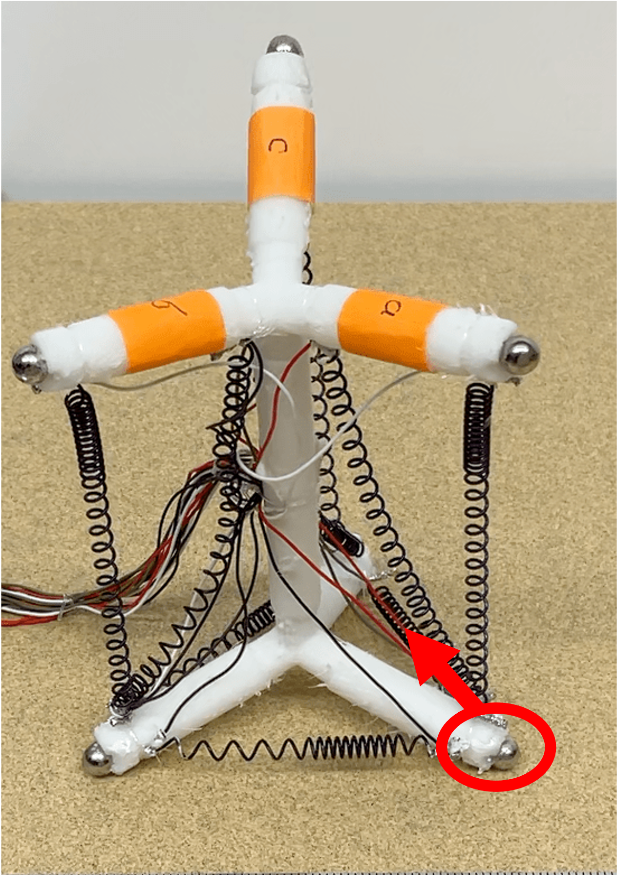
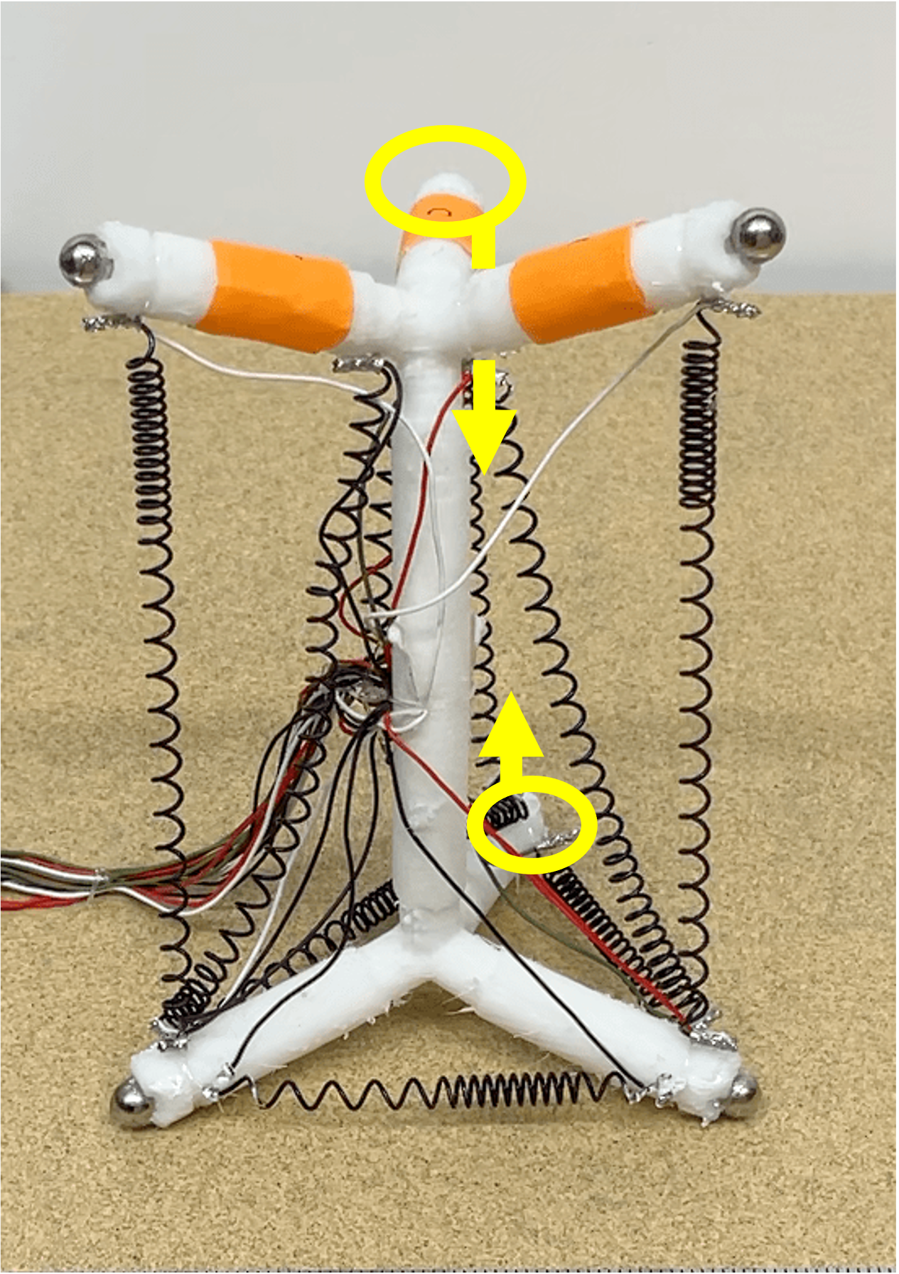
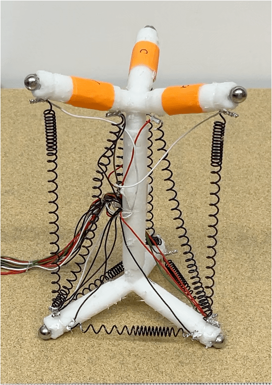
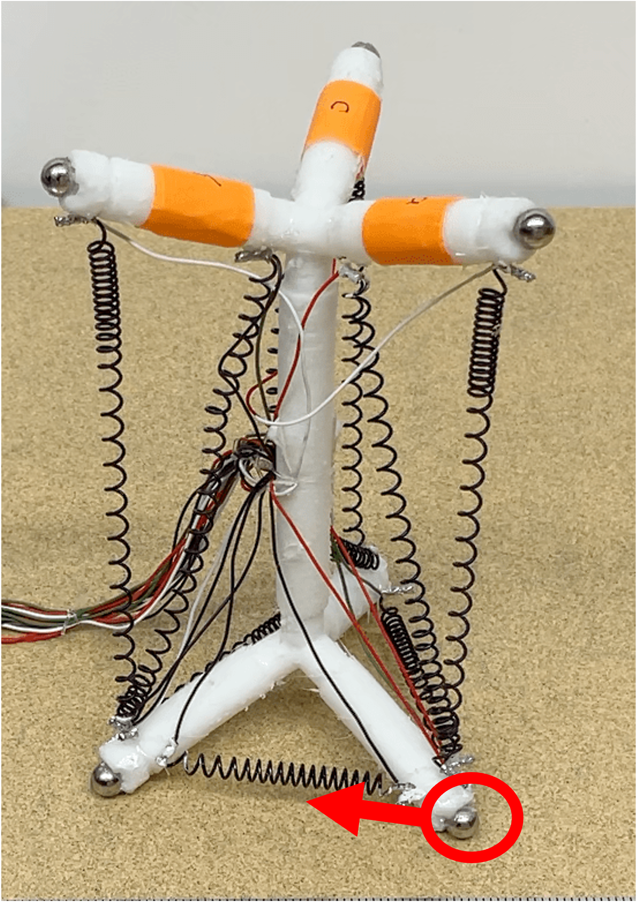
An individual module is composed of a skeleton, SMAs and spherical magnets. The shape of the skeleton is a pair of symmetric stacked tetrahedrons, inspired by the geometry of a tetrahedral molecule (Fig. 1(a)). Each tetrahedron is composed of four equal-length bars. The angle between each two neighboring bars is , which is the same as the bond angle of the tetrahedron molecule. The diameter of each bar is smaller near the connection point for better flexibility, with grooves for mounting SMAs. The skeleton is printed with flexible TPU material with an infill density of 90% to achieve a stronger adversarial bending force that helps restore a module’s original shape after SMA contraction.
Given the small size of each module and the need for nine actuators in order to achieve our target locomotive gaits and manipulation capabilities, we used one-way SMA (shape memory alloy) coils (coil diameter, ; wire diameter, , Dynalloy) to actuate the robots. The end of each spring SMAs is crimped with fishing wire and electric wire in a ferrule and mounted to the grooves in the skeleton with the fishing wire. The detwinned Martensite rest length of each SMA is longer than the distance between two grooves to make sure that they can be extended when the skeleton deforms because of SMA actuation. The Austenitic (actuated) rest length of the actuators is // (vertical/diagonal/horizontal). When installed, the detwinned Martensite rest length is set to be //, though this exact length changes with actuation cycles due to variance in antagonistic forces applied by other SMA actuators and the elastic energy stored in the deformed soft skeleton.
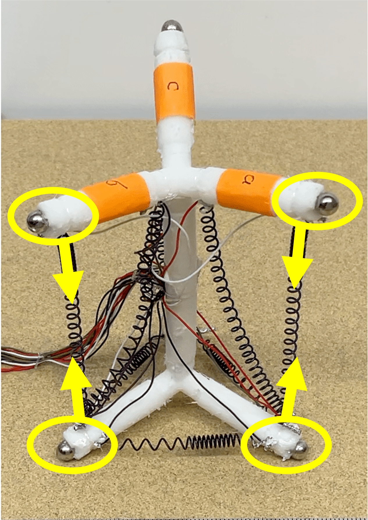
Spherical magnets are affixed at the end of each tetrahedral limb to enable the modules to connect together. We oriented the polarity of the magnets in a circle as described in [29], where each magnet in the loop is aligned head-to-tail and the magnetic field inside the loop is either clockwise or counterclockwise. Therefore, once all the magnetic balls are glued on the modules with the same magnetic field direction, any modules can then be attached together from all directions.
III-B Choice of spherical magnets
The pull force of the spherical magnet has a strongly influences on the attachment property. We tested four sizes of spherical magnets: 3/16”, 1/4”, 5/16”, and 3/8”. Six experiments were done to evaluate their attachment properties including the maximum distance that two modules can be attached by magnetic force only and the minimum length that SMAs are allowed to be contracted to avoid detachment of magnetic connectors. The maximum distances were tested in two cases: four feet facing each other (8 magnets) and two feet facing each other (4 magnets). The minimum contraction length were tested in four cases: two feet connected (Fig. 2(a)) and four feet connected (Fig. 2(b)) while only SMAs in one module contracted and SMAs in two modules contracted. Experimental results are shown in Table. I, where is the Austenitic rest length of the vertical SMA. Results indicate that the magnetic connection does not break even with maximum SMA actuation. Based on the results, we chose the 1/4” diameter for locomotion and peristaltic manipulation because of its low cost, and chose the 5/16” magnets for gripper experiments that required larger deformation while keeping modules connected.
| Diameter (inch) | Pull Force (lb) | Max attach distance for 8-magnets (cm) | Max attach distance for 4-magnets (cm) | Min length for 2 SMAs in Fig. 2(b) (cm) | Min length for 1 SMA in Fig. 2(b) (cm) | Min length for 4 SMAs in Fig. 2(a) (cm) | Min length for 2 SMAs in Fig. 2(a) (cm) |
|---|---|---|---|---|---|---|---|
| 3/16 | 1.04 | 1.5 | 1 | 1.52 | 4 | 5.5 | 5.5 |
| 1/4 | 1.86 | 2 | 1.5 | 1.52 | 1.52 | 4 | 4 |
| 5/16 | 2.52 | 3 | 2 | 1.52 | 1.52 | 2 | 2 |
| 3/8 | 3.69 | 5 | 3 | 1.52 | 1.52 | 1.52 | 1.52 |
(top-down view of bottom legs)
IV Single Module Locomotion & Attachment
| Pattern | Grab-and-pull | Shuffling | Combined | Combined + Vibration | Combined + Vibration + Cooling Fan | Combined + Vibration with Thinner SMAs | 3-module Locomotion |
|---|---|---|---|---|---|---|---|
| Time (mins) |
IV-A Analysis of Locomotive Gaits
We have chosen two gaits (and a combination of them) for single-module locomotion. The purpose of locomotion for single module is to move towards other modules to assemble into a 3-module unit for locomotion, where 3-module units are utilized to assemble into a larger structure for manipulation. While there are gaits that roll modules end-over-end to achieve fast locomotion, the need for precise control during attachment motivated us to instead explore gaits that cause the robot to slide along the floor in an upright configuration.
Both gaits operate on the same principle: the module is controlled in order to move the center of mass to reduce the friction at contacts that are sliding forwards, while increasing friction at contacts that are planted.
IV-A1 Single-module Gait #1: Grab-and-pull
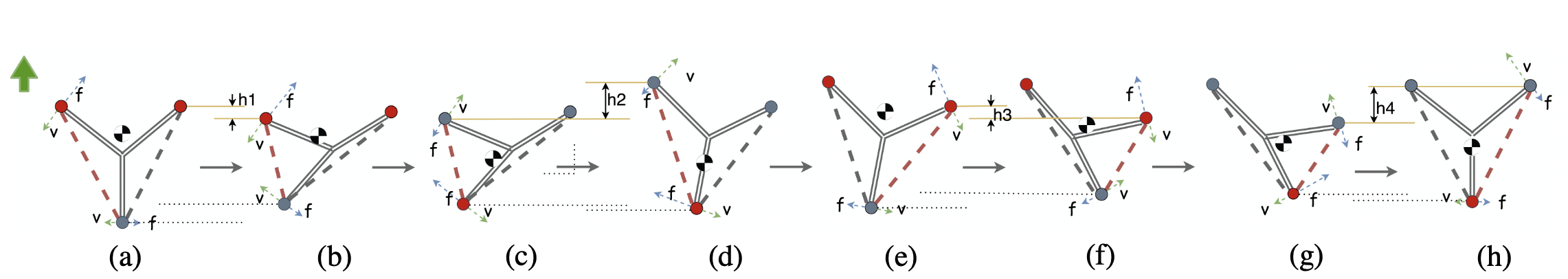
In this grab-and-pull gait (akin to breaststroke), the first step shifts the center of mass backwards to plant the back leg while contracting the front SMA to slide the front legs forward (Fig. 4a). Similarly, during release of the front SMA, the robot rocks so that the center of mass lies over the front two feet (Fig. 4b). Therefore, after switching the center of mass from back to front, the distance moving forward (Fig. 4b) is equal to , where and are the same when the center of mass is not switched and kept in the center.
IV-A2 Single-module Gait #2: Shuffling
In this pattern, the robot walks by dragging left and right feet alternately without lifting the feet from the ground. The physical analysis behind it is similar to the grab-and-pull pattern. Fig. 3 shows the whole process, where the center of mass is switched to front during contraction of left SMA and switched backward during recovery process to intensify the impact of forward friction and weaken the impact of backward friction. Then the right SMA works in the same way symmetrically.
Importantly, if the contraction time of left and right SMAs are different, the robot can rotate to the direction that is less contracted, which means with this pattern, the upright robot can move to arbitrary locations and orientations in the plane.
IV-A3 Single-module Gait #3: Combined
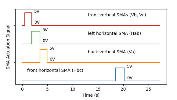
We used the property that motion of the center of mass is opposite in the two patters to create a combined pattern with faster locomotion. Specifically, the combined gait is “left →front →right →front”. Fig. 6 shows an example where the center of mass switches from front to back when left foot is contracted & released and then the front bottom SMA is contracted – the corresponding control signal is shown in Fig. 5 (SMAs are labeled in Fig. 1(a); The labels Vx, Dx, Hxx represent vertical, diagonal and horizontal SMAs respectively, where x/xx is determined by the limb label). We ultimately selected this combined gait for the single-module locomotion and attachment task due to its speed advantage.
IV-B Experiments
IV-B1 Locomotion Performance
To control the SMAs, we used Arduino and DC power supply. 120 grit sandpaper supplies a coarse locomotion surface . To reduce drag, we used light, flexible silicone insulated stranded wires for the tether.
We conducted some experiments to validate the effectiveness of the two locomotion patterns. The grab-and-pull gait took to travel , or body lengths per second (), where was used to actuate and the rest was used to cool the SMA actuators. The shuffling pattern took to travel , or , where was used to actuate. For the combined gait, the time cost of moving forward is (median of 10 trials), or , where the actuation time is .
IV-B2 Strategies To Increase the Speed
Given the slow speeds observed with the gaits mentioned above, we experimented with several methods of expediting the locomotion (Table II).
Vibration: Since legs are unable to be lifted off the ground, backward friction between the sliding legs and the ground inhibits movement speed. To reduce this friction, we alternately actuate and relax the back vertical SMAs on a : (actuation : cooling) interval.
Cooling Fan: We tested putting a fan opposite to the direction of motion to simulate locomotion in outdoor conditions.
Multiple Thinner SMAs: Approximately of the locomotion time is spent waiting for the SMAs to cool and expand. We tested replacing single SMAs with multiple thinner SMAs to increase the surface area and speed cooling, similar to the “stacked-ribbon” design described in [6].
IV-C Attachment Between Single Modules
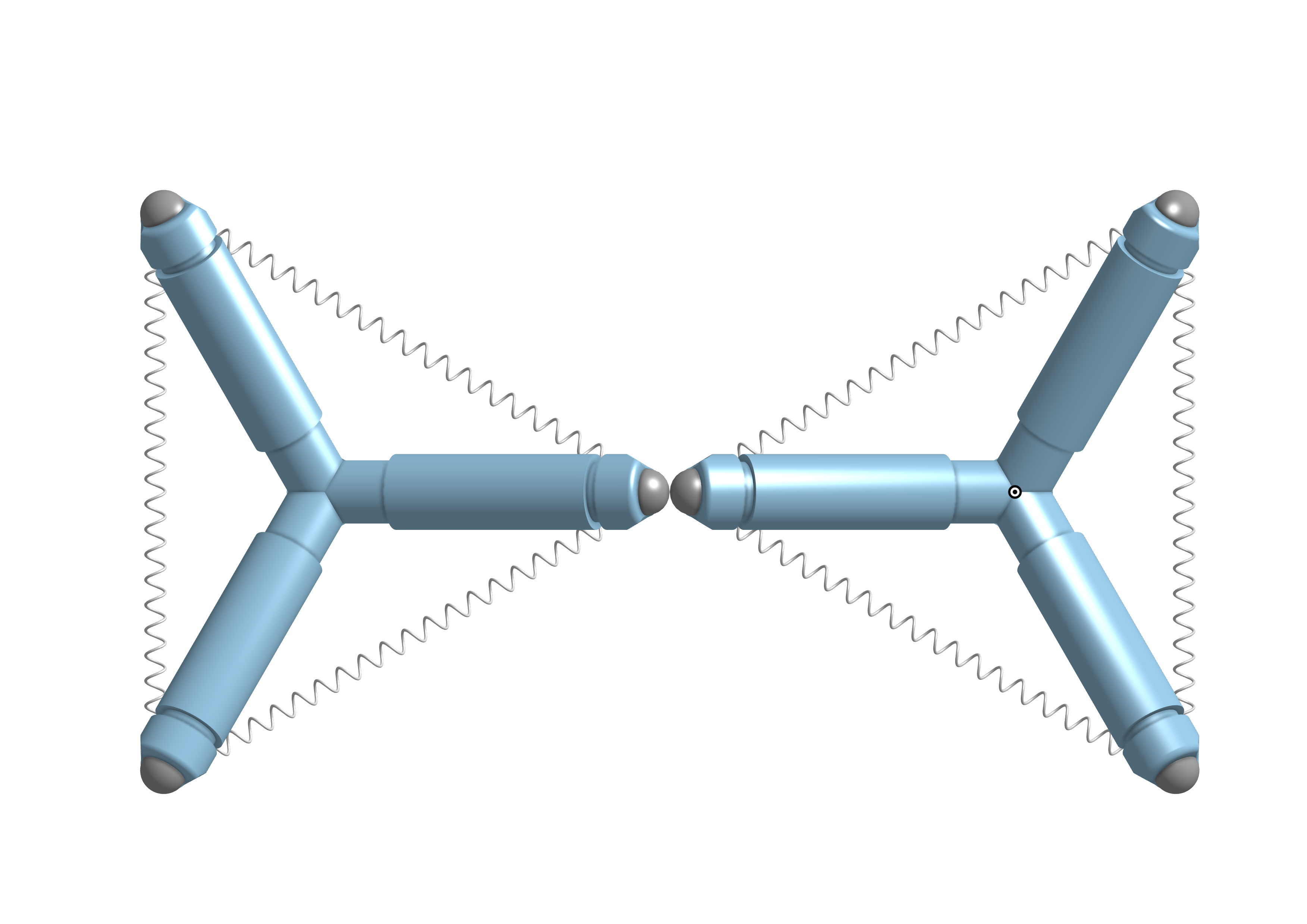
Once two modules are in close proximity they enter an attachment protocol to ensure a fully connected four-magnet bond (Fig. 7). During this protocol, one module actively moves towards the other one while the other module waits and cooperates with the active module. Once two modules are close enough, the head of the passive module leans outward to prevent the upper magnets from attaching together, since an initial attachment of the top magnetic balls can prevent successful attachment of the bottom two balls (because the modules are unable to shift their center of gravity sufficiently to slide the bottom feet).
When at least one pair of bottom feet has been attached as shown in Fig. 7(b), all the SMA actuators on the two modules are commanded to release until returning to initial states. During this process, other pairs of magnetic balls will be attached automatically as shown in Fig. 7(c). For those exceptional cases where not all the remaining magnetic balls are attached automatically, the strategy we used is to contract the four neighboring vertical SMAs simultaneously and then contract the two front horizontal SMAs at the same time.
IV-D Attachment Test
To test this attachment strategy we conducted an experiment where we attached one of the bottom magnets and varied the alignment angle between the modules (Fig. 7(b) is an example with an approximately alignment angle). We tested 5 trials for each angle (, , , , ). The success rate was 100% for angles less than or equal to 90 degrees, while 4 out of 5 trials with succeeded. Furthermore, for trials with angle , , and , the remaining pair of magnetic balls automatically attached during recovery process. For trials with angle , 2 trials out of 5 required an additional approach after recovery to help with attachment.
V 3-module Locomotion & Attachment
The locomotion pattern of 3-module is like a three-legged race, where the feet in between are strapped by magnetic balls and only the left most and right most feet can move freely.
(left-leg step, top-down view of bottom legs)
V-A Physical Analysis of “Three-legged Race” Pattern
The principle of moving forward for 3-module unit is similar to the combined Shuffling and Grab-and-pull pattern of single module locomotion, where left foot and right foot are alternately moving forward, and the front SMA is actuated to speed up the forward movements. The main difference and advantage of three-module locomotion is that given the greater number of ground contact points, feet can be lifted and advanced in the air while maintaining stability, thereby eliminating sliding friction and enabling significantly faster locomotion as compared to a single module.
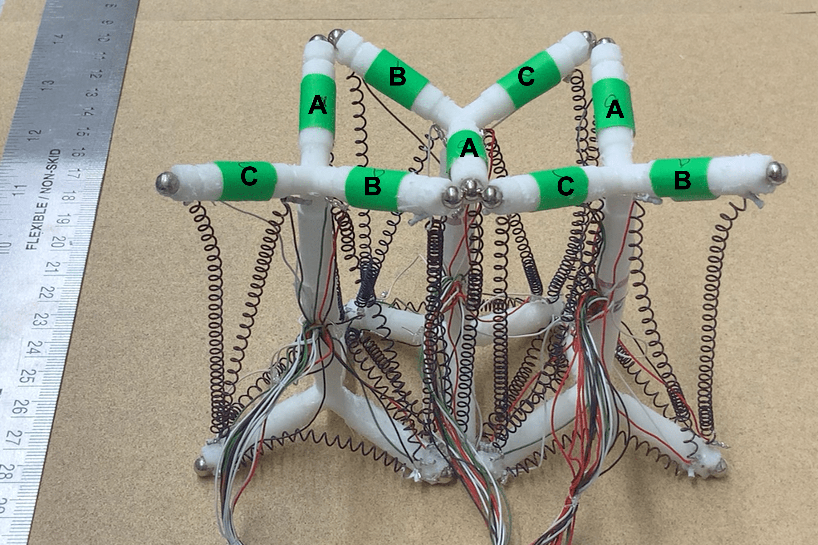
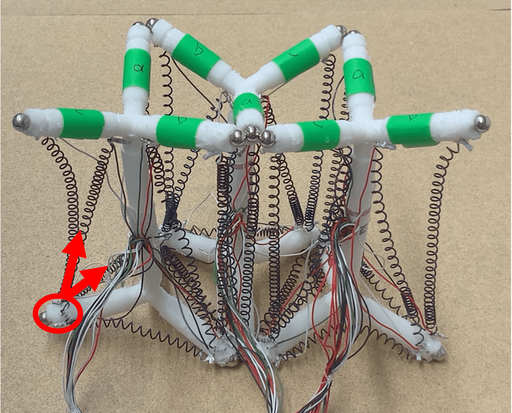
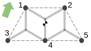
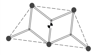
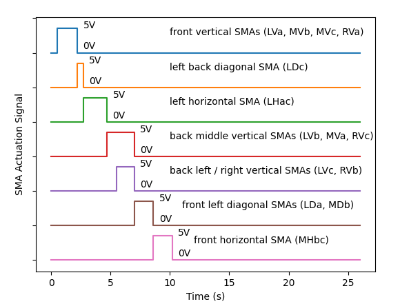
Take the left foot as an example. The first step is to raise the left foot and move it forward in the air (Fig. 9(b)). The second step (Fig. 9(c)) plants the outside back feet (nodes 3 & 5) by switching the center of gravity backward while lifting and advancing the center-back leg (node 4). The last step is to raise the front left foot (node 1) and actuate the front horizontal SMA to reduce the friction that influences the movement. As shown in Fig. 9(d) only three feet remain on the ground. Finally, the three-module can move the left side of the body forward (Fig. 9(e)). The sequence will then be mirrored for the right side. Photos of the gait sequence shown in Fig. 8 and Fig. 10 shows the control signal for moving the left foot forward (Lx, Mx, Rx represent the SMAs on the left, middle and right modules separately, with x labelled in the same way as in Fig. 1(a), with limb labels (A, B, C) for each module shown in Fig. 8(a)).
V-B Experiments
To move forward for , the running time of 3-module unit was (median of 5 trials) and the cooling time for each cycle was out of , or . This motion is faster than a single module as each foot can be lifted and then moved forward in air, allowing more forward displacement during each cycle.
V-C Attachment Between 3-module Units
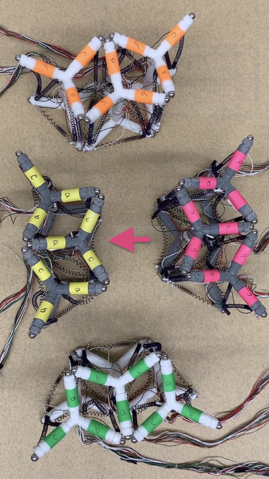
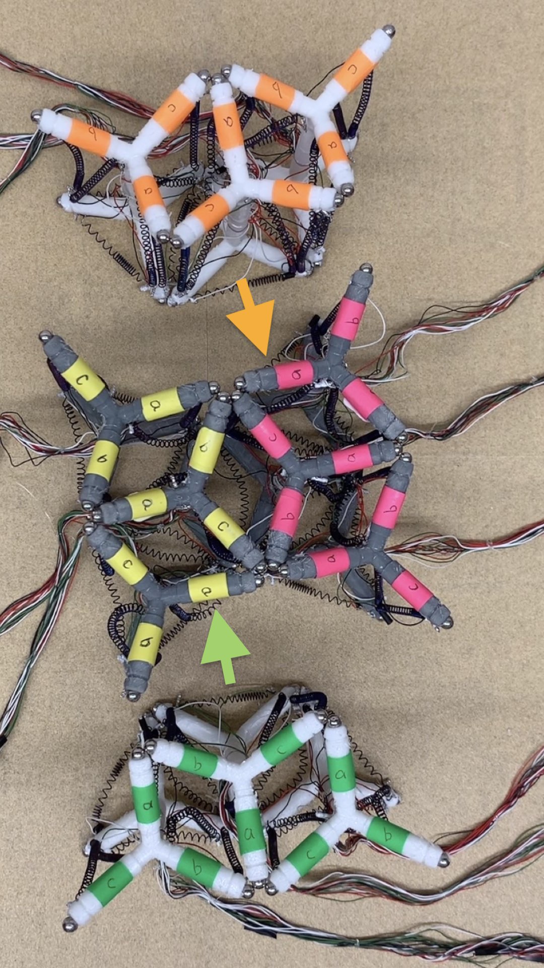
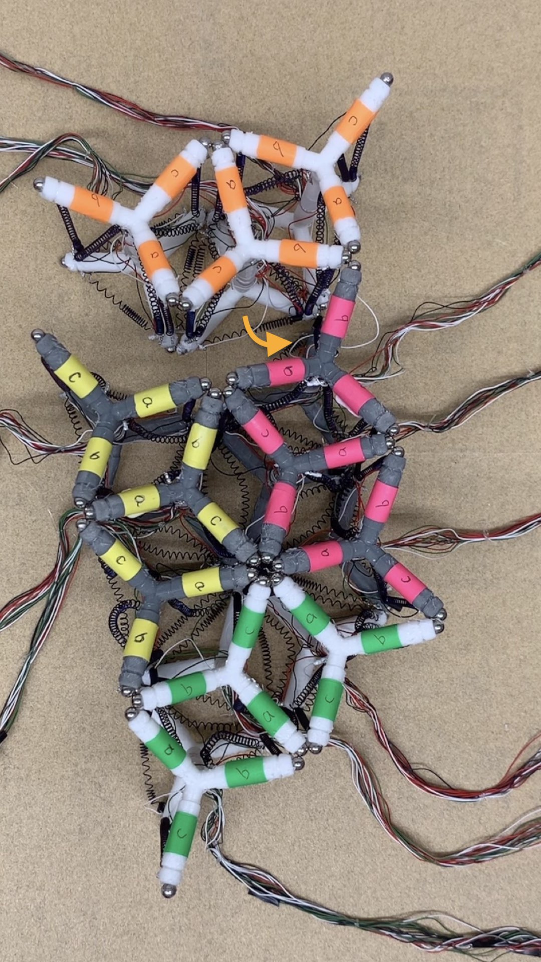
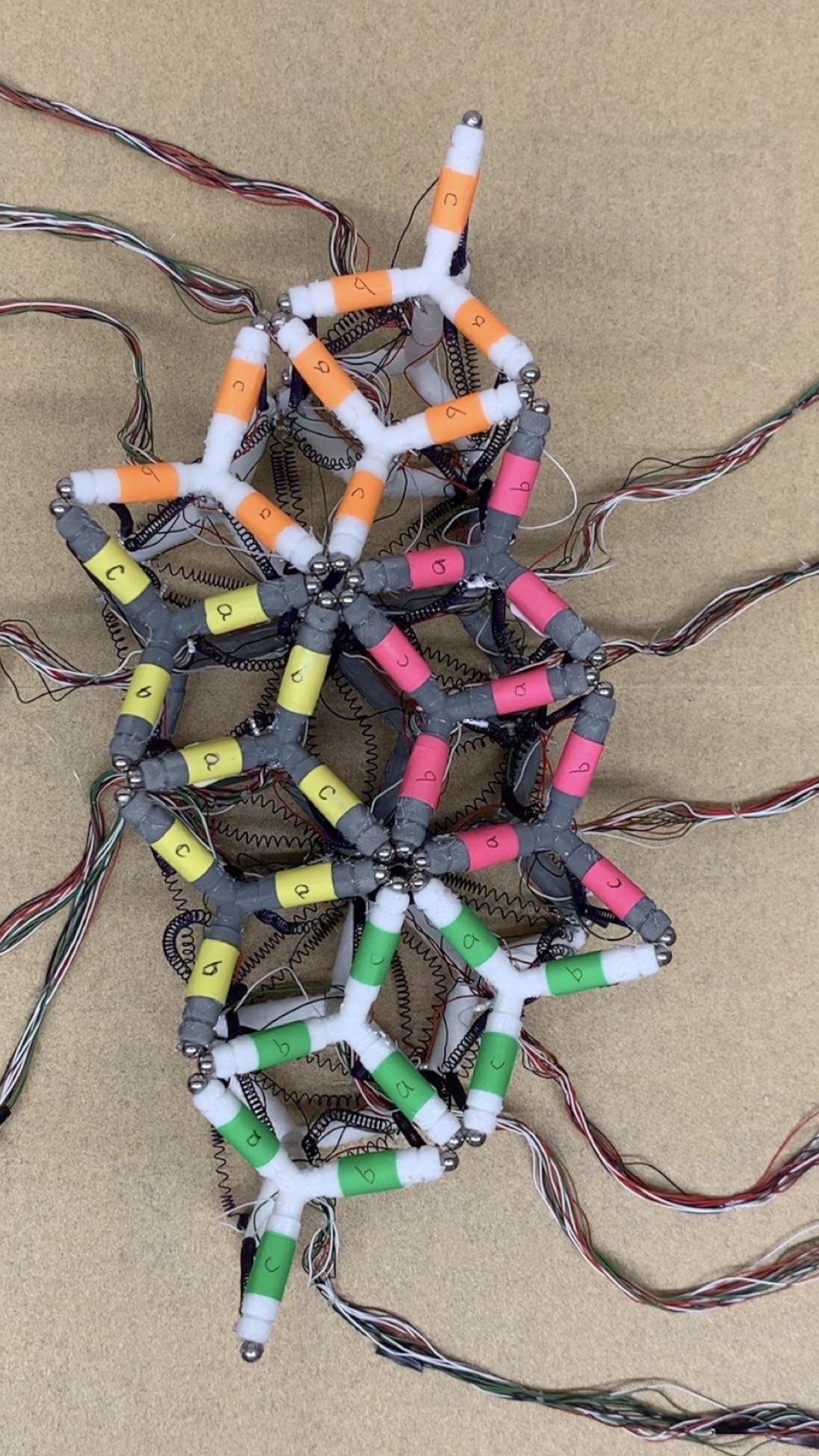
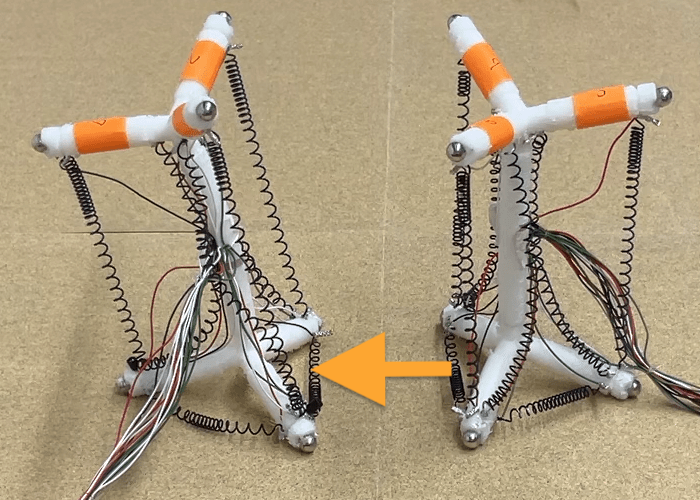
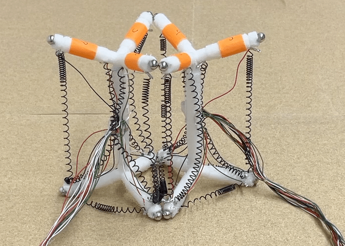
Fig. 1(c) shows an example of attaching four three-module groups together. Unlike single-module attachment, the passive module unit waits motionlessly instead of leaning backward to cooperate, due to the complexity that would be required for the leaning motion. Moreover, since the unit will not lean forward as the single module does during locomotion, either the bottom magnetic balls will be attached first when unit is leaning backward or all balls (top and bottom) will attach simultaneously when the unit is upright.
When a 3-module unit approaches the lattice it is common for all magnetic connection points to snap together nearly simultaneously, but this is not always the case. Fig. 1c3 shows a case where only a partial connection is made between the orange unit and the lattice. In this case, we used a rotation motion to pivot the unit around the connected points until a full connection was reached. Closing the loop with sensing and fully automating this process is a next step in future work.
VI Non-prehensile Manipulation
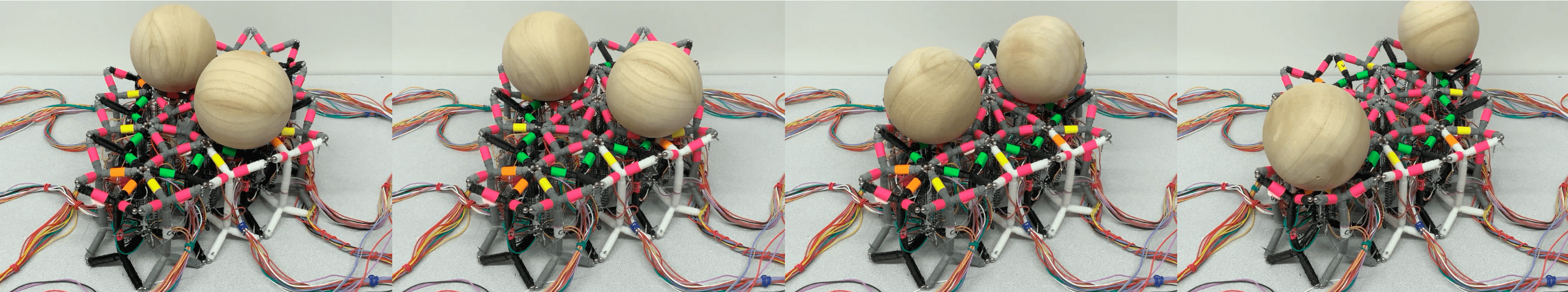
In this section, we describe strategies to roll a single ball or multiple balls along the surface of the structure. Ultimately, we imagine transporting other objects or even modules themselves along the surface, using lattice deformation as a whole-body manipulation strategy.
VI-A Bi-directional Linear Manipulation with SMAs in 3D
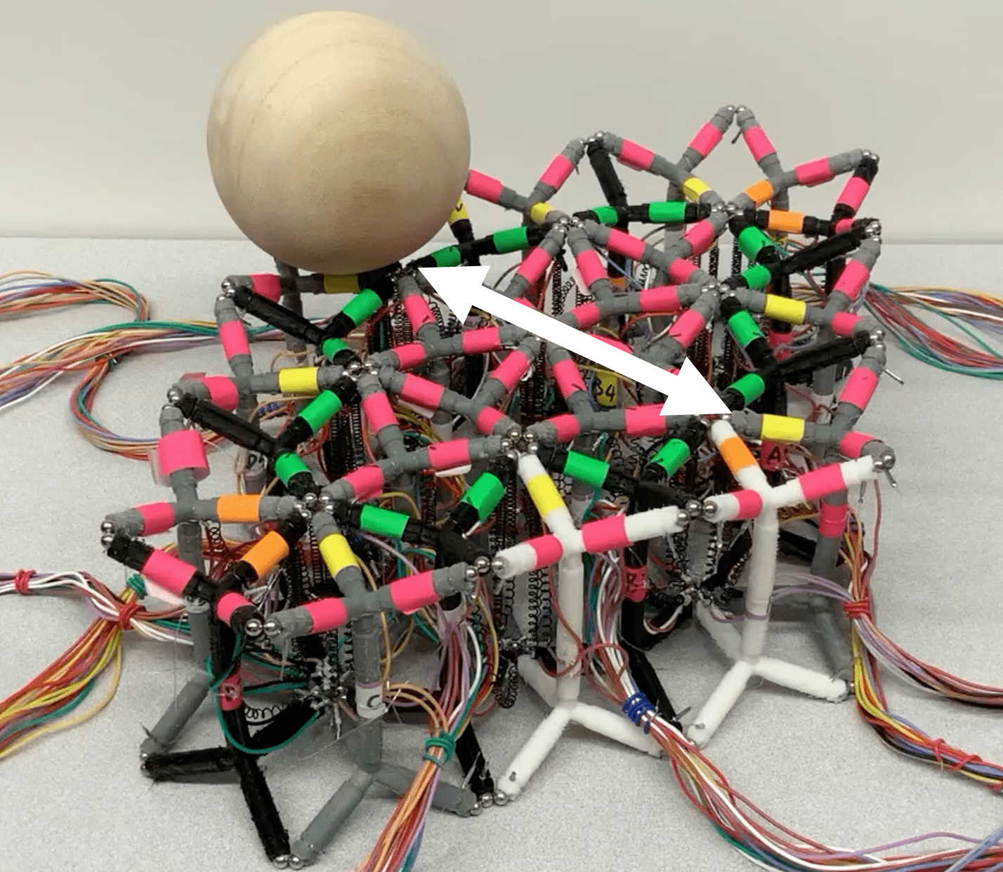
Vertical SMAs are actuated to change the shape of the top surface to make the ball roll. Fig. 14(b) shows an example of bi-direction linear manipulation.
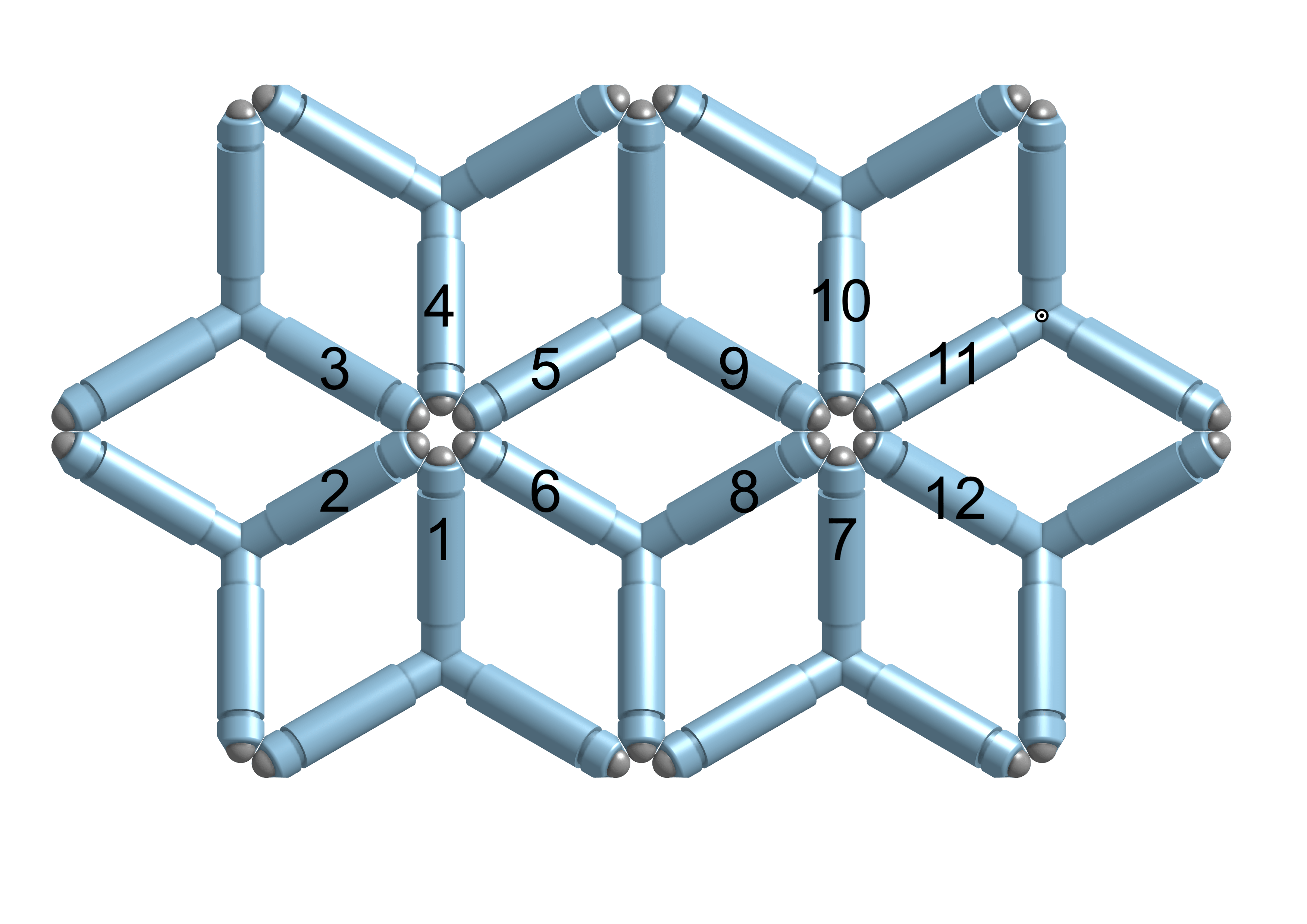
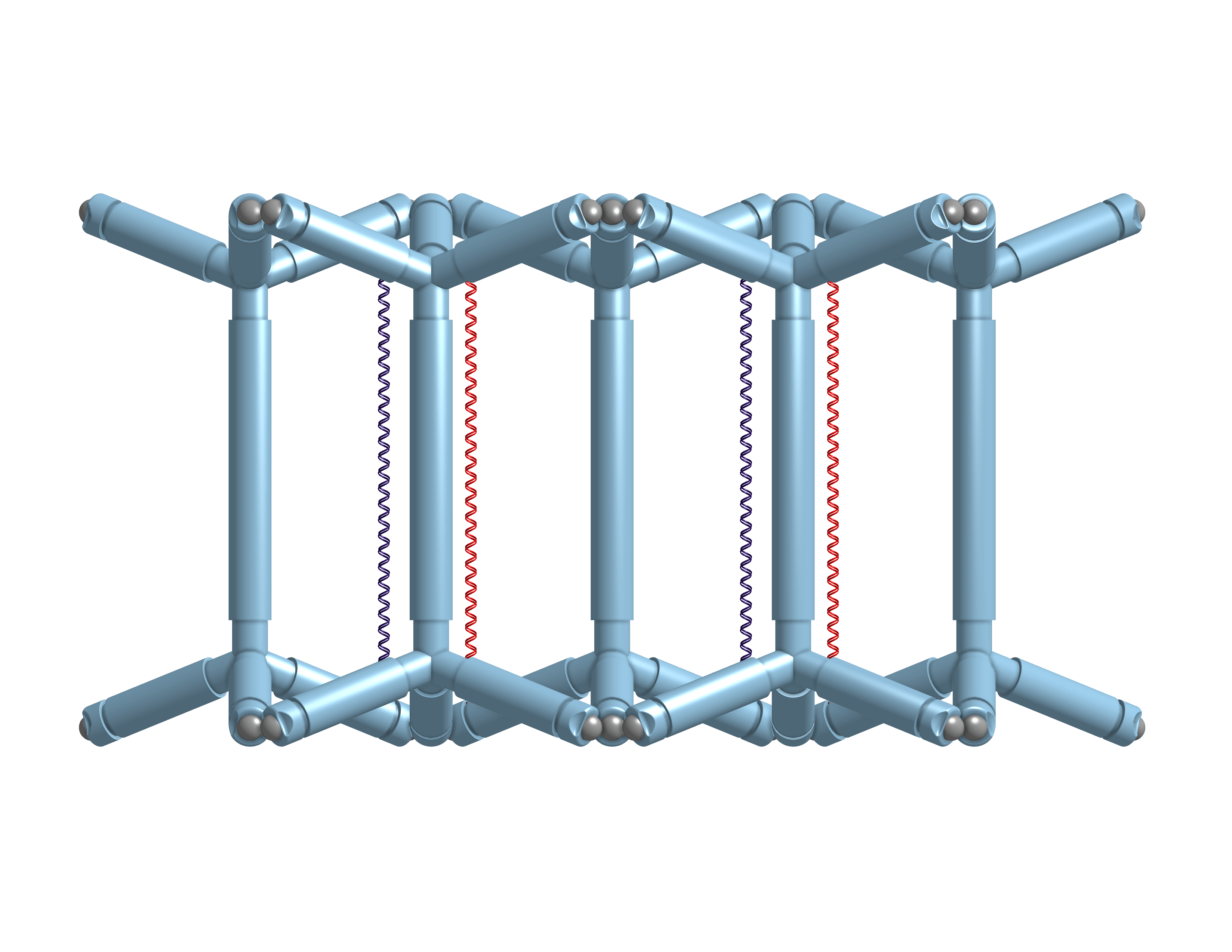
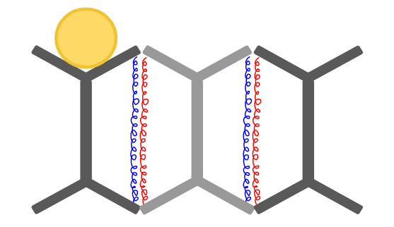
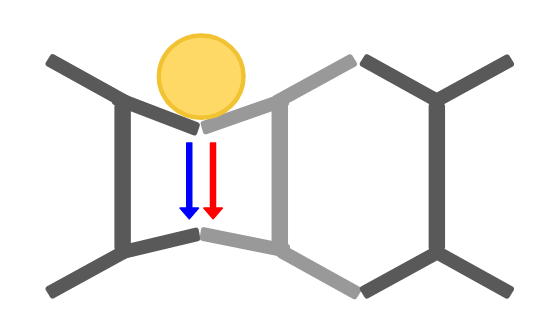
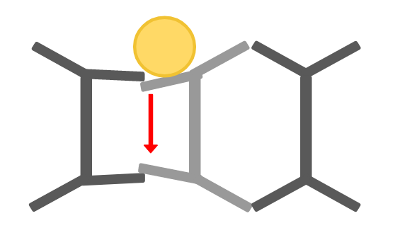
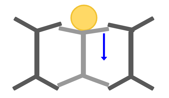
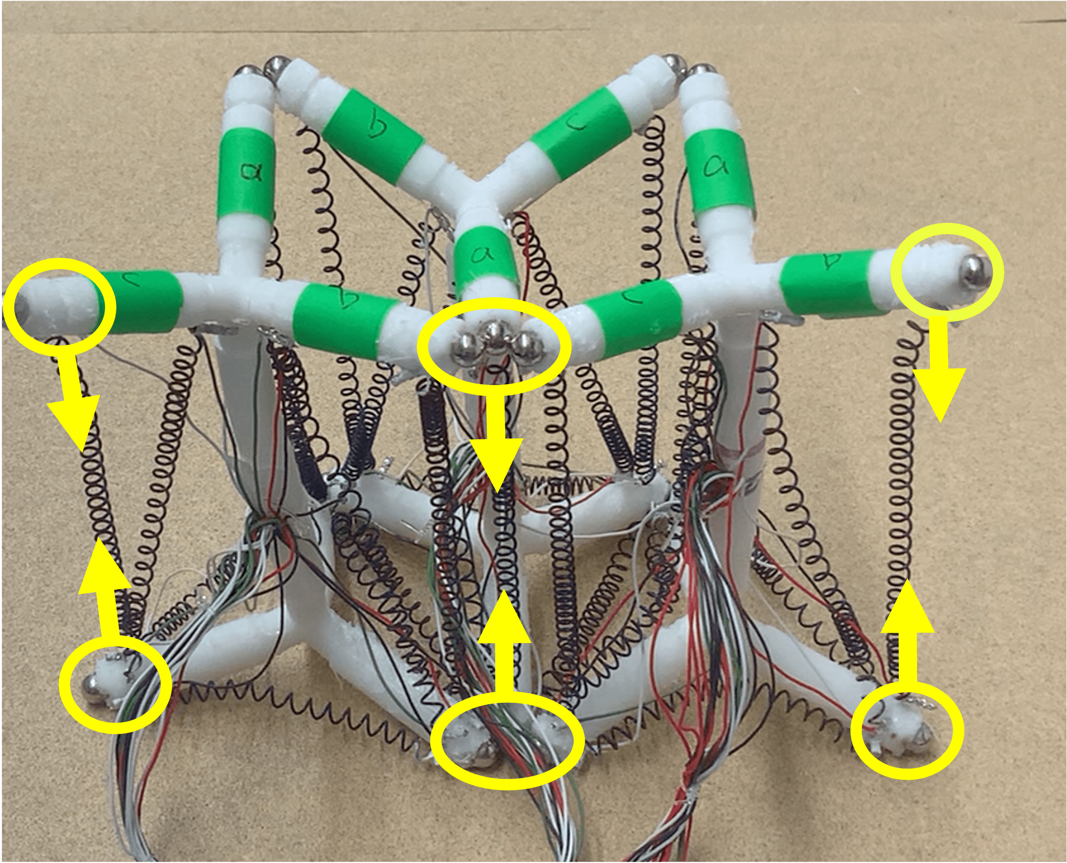
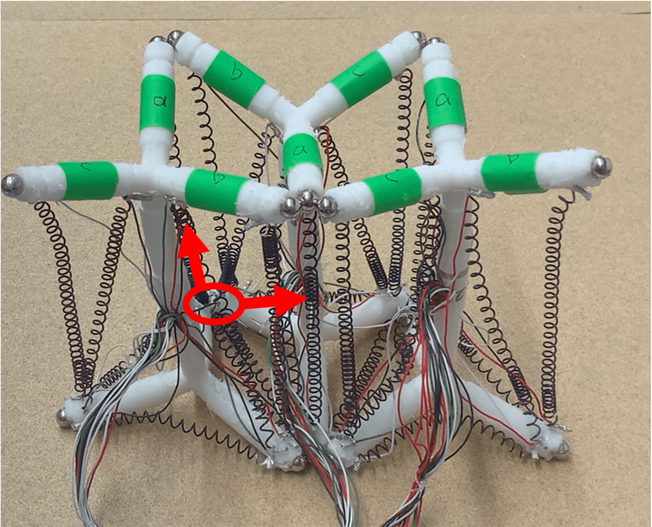
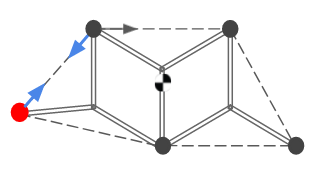
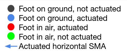
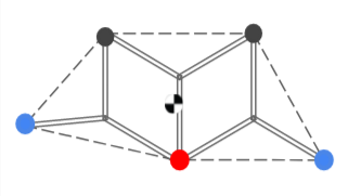
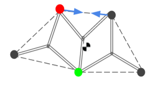
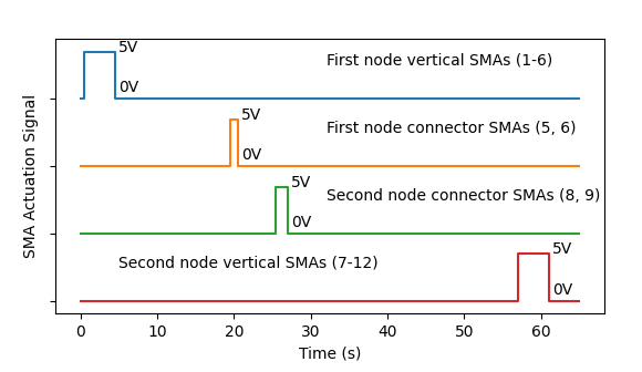
An example of moving a ball from the left node to the right node is shown in Fig. 12. The first step is to drag the left node down vertically by actuating six connected vertical SMAs (shown in Fig. 12(b)). During release of these SMAs, the height of left node increases gradually. When the left node rises, the ball might drop either left and right; to avoid this, before the left node becomes flat, the first node connector SMAs (marked in red in Fig. 12(c)) is actuated to give the ball velocity in the desired direction. After 5 seconds, the second node connector SMAs (marked in blue in Fig. 12(d)) is actuated to give the ball a rightwards velocity towards a stable position on top of the middle module. The corresponding control signal is shown in Fig. 13 (vertical actuated SMAs are labeled in Fig. 11(a)).
VI-B Path Control of a Ball
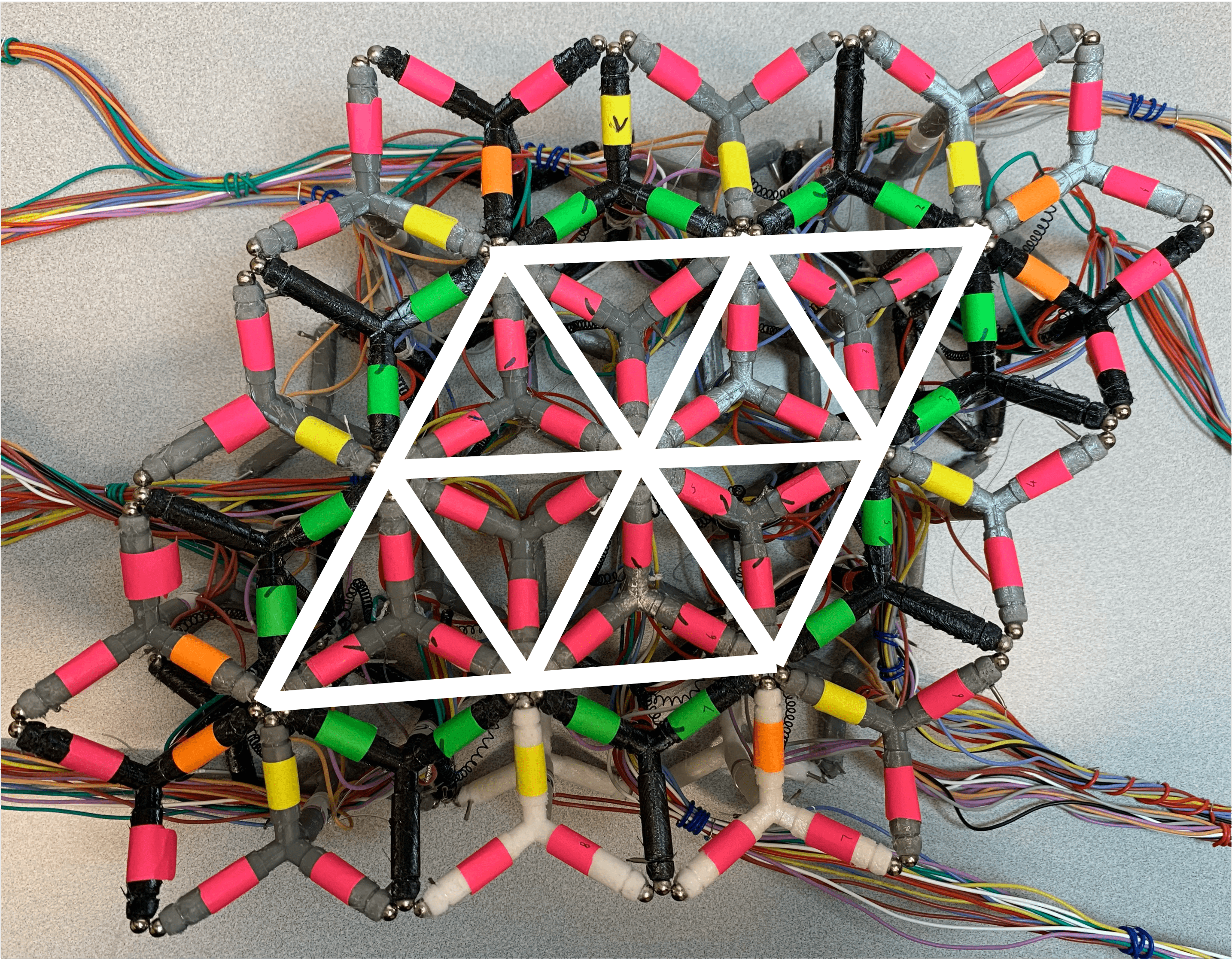
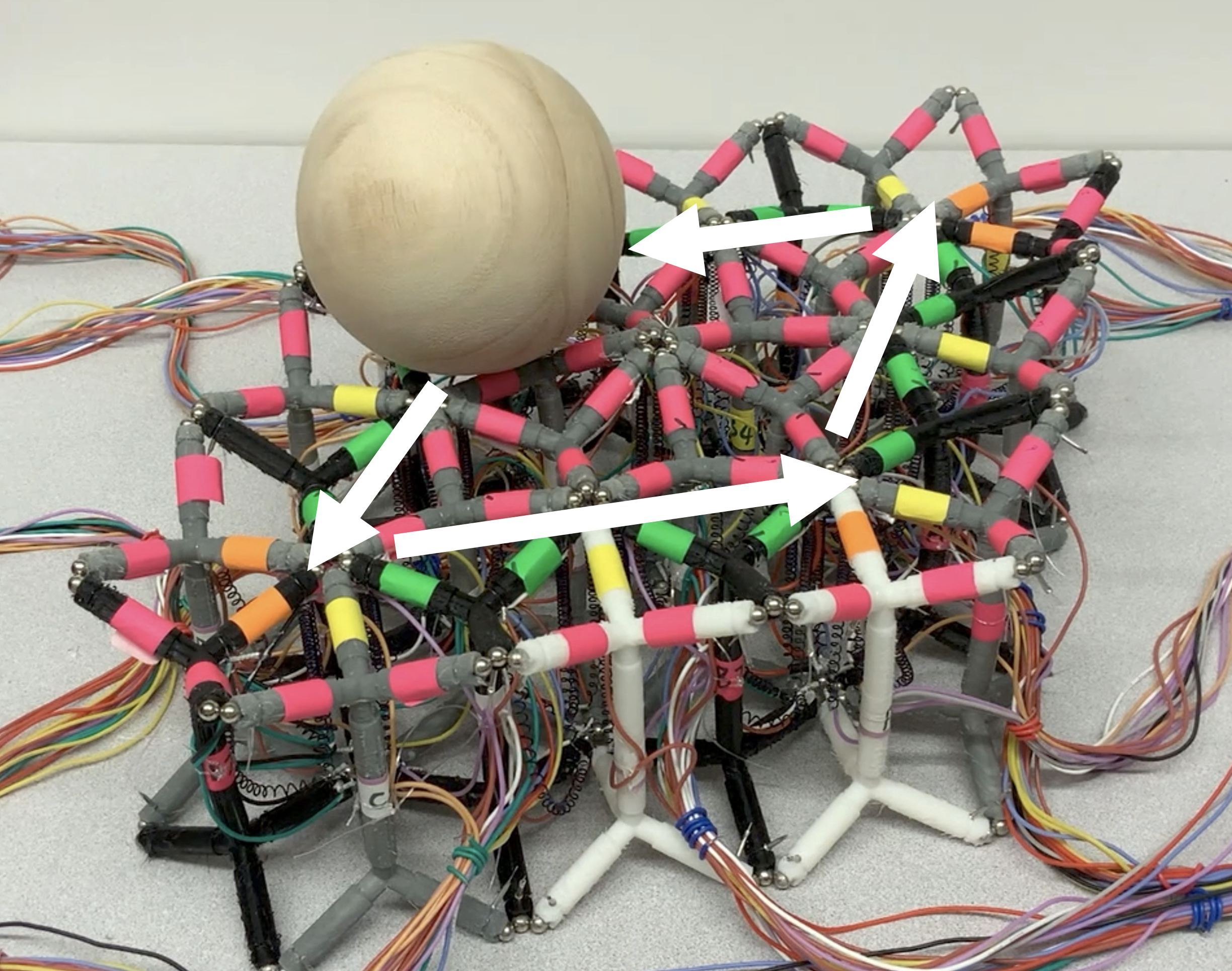
Using the same principle, adding additional modules to the lattice allows us to do path control of a ball along the top surface. Fig. 14(a) shows an example of a 3x3 grid, where white edges are the allowed paths to move through. Except bi-directional manipulation, we also tested parallelogram manipulation on this surface (Fig. 14(c)) and manipulating two balls on the top surface, where as Fig. 1(d) shows, two balls move in opposite directions without touching each other.
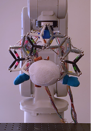
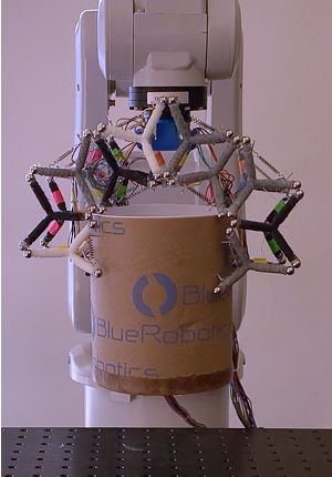
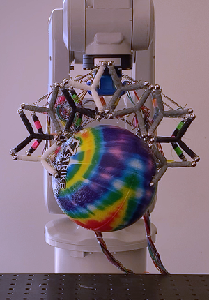
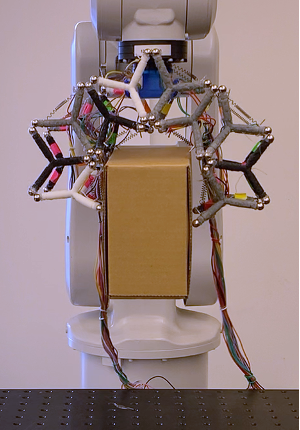
VII Gripper formed from modules
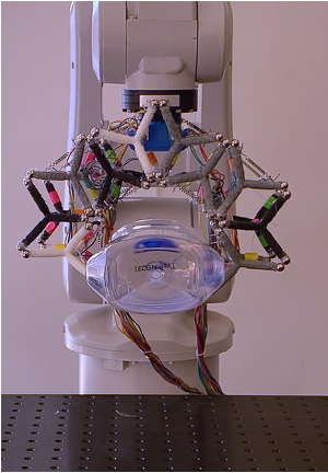
We have also tested using a module-based gripper to grasp various objects, as shown in Fig. 1(e). Top horizontal SMAs are added for each module such that the object can be grasped when both top and bottom horizontal SMAs on the inside boundary are actuated. To grasp larger objects, top and bottom horizontal SMAs on the outside boundary are actuated to open the gripper first. To avoid detachments between modules easily when grasping heavy objects, we used larger ball magnets with 5/16” diameter and lbs pull force.
Objects with different weight/shape/size/surface as shown in Fig. 1(e) were tested, and the results are shown in Table III. The gripper appears capable of gripping a variety of objects with a success rate that varies depending on the roughness of the gripper and the weight/shape/size/surface of the object. To increase the success rate, future work could test increasing the roughness of the gripper, using magnets with higher pulling force, using softer skeletons to allow more deformation, or trying new arrangements of modules to grasp different objects.
VIII Conclusion and Future work
In this paper, we instantiated soft lattice modules that behave both independently and collectively. Using these lattice modules, we demonstrated preliminary steps toward the self-assembly of robotic lattice structures and employed several behaviors to perform collective and coordinated tasks.
Our system has several limitations and opportunities for further development. At present, all the modules are tethered to an Arduino which controls the lattice as a whole. To allow modules be self-contained and autonomous, on-board computing, power, and sensing would be required. The modules would need communication through a contact-based mesh scheme or a wireless scheme. Methods of realizing distributed control of the lattice would need to be implemented.
Our single module locomotion strategy relies on friction, so the speed is limited even on rough surfaces. However, for 3-module locomotion, since the feet can be lifted, the speed is much faster. We plan to explore moving more modules together for centipede-type locomotion, and improve module design to make it walk individually instead of sliding.
Our system is capable of self-assembly, but the magnets present a challenge for self-disassembly. One potential approach could use the principle of “tug of war” to generate sufficient detachment force, but detaching multiple connection points simultaneously may be difficult and a hardware modification is perhaps necessary for this purpose.
Yet another direction for further development lies in simulation. We have built a simple simulation using an energy-based quasi-static model that estimates the configuration with the minimal potential energy using Lagrange multipliers. Our model assumes a pseudo-rigid bodied skeleton and requires further development to better reflect the system dynamics .
References
- [1] Tamio Arai, Enrico Pagello and Lynne E Parker “Advances in multi-robot systems” In IEEE Transactions on robotics and automation 18.5 Citeseer, 2002, pp. 655–661
- [2] Joran W Booth et al. “OmniSkins: Robotic skins that turn inanimate objects into multifunctional robots” In Science Robotics 3.22 Science Robotics, 2018
- [3] A.S. Boxerbaum, K.M. Shaw, H.J. Chiel and R.D. Quinn “Continuous wave peristaltic motion in a robot” In The International Journal of Robotics Research 31.3 SAGE Publications Sage UK: London, England, 2012, pp. 302–318
- [4] J. Bruce et al. “ SUPERball: Exploring tensegrities for planetary probes” In 12th International Symposium on Artificial Intelligence, Robotics and Automation in Space (i-SAIRAS), 2014
- [5] Jonathan Bruce, Ken Caluwaerts, Atil Iscen, Andrew P Sabelhaus and Vytas SunSpiral “Design and evolution of a modular tensegrity robot platform” In 2014 IEEE International Conference on Robotics and Automation
- [6] Trevor L Buckner and Rebecca Kramer-Bottiglio “Design Parameters for Stacked-Ribbon Shape-Memory Alloy Bending Actuators” In 2021 IEEE 4th International Conference on Soft Robotics (RoboSoft) IEEE
- [7] Zhuxiang Chen, Chuanwu Zhao, Yu Zhang, Yanhe Zhu, Jizhuang Fan and Jie Zhao “C-Balls: A Modular Soft Robot Connected and Driven via Magnet Forced” In Journal of Physics: Conference Series, 2019
- [8] Q. He and M.A. Post “ An Adaptable Robotic Snake Using a Compliant Actuated Tensegrity Structure for Locomotion” In Annual Conference Towards Autonomous Robotic Systems, 2020, pp. 70–74 Springer
- [9] Xiaonan Huang, Michael Ford, Zach J Patterson, Masoud Zarepoor, Chengfeng Pan and Carmel Majidi “Shape memory materials for electrically-powered soft machines” In Journal of Materials Chemistry B 8.21 Royal Society of Chemistry, 2020, pp. 4539–4551
- [10] Sen W Kwok et al. “Magnetic assembly of soft robots with hard components” In Advanced Functional Materials 24.15 Wiley Online Library, 2014, pp. 2180–2187
- [11] Chiwon Lee et al. “Soft robot review” In International Journal of Control, Automation and Systems Springer, 2017
- [12] Hajun Lee et al. “3D-printed programmable tensegrity for soft robotics” In Science Robotics 5.45, 2020
- [13] Steven Lessard et al. “A bio-inspired tensegrity manipulator with multi-DOF, structurally compliant joints” In 2016 IEEE/RSJ International Conference on Intelligent Robots and Systems (IROS), 2016 IEEE
- [14] Shuguang Li and Daniela Rus “JelloCube: A Continuously Jumping Robot With Soft Body” In IEEE/ASME Transactions on Mechatronics 24, 2019, pp. 447–458
- [15] Chao Liu, Michael Whitzer and Mark Yim “A Distributed Reconfiguration Planning Algorithm for Modular Robots” In IEEE Robotics and Automation Letters 4.4, 2019, pp. 4231–4238
- [16] Chao Liu and Mark Yim “Reconfiguration Motion Planning for Variable Topology Truss” In 2019 IEEE/RSJ International Conference on Intelligent Robots and Systems (IROS), 2019, pp. 1941–1948
- [17] Ignacio Mas and Christopher Kitts “Object manipulation using cooperative mobile multi-robot systems” In Proceedings of the World Congress on Engineering and Computer Science 1, 2012
- [18] Brian Mirletz, In-Won Park, Thomas Flemons, Adrian Agogino, Roger Quinn and Vytas Sunspiral “Design and Control of Modular Spine-Like Tensegrity Structures”, 2014
- [19] Francesco Mondada et al. “SWARM-BOT: A new distributed robotic concept” In Autonomous robots 17.2 Springer, 2004, pp. 193–221
- [20] Stephen A Morin et al. “Using “Click-e-Bricks” to Make 3D Elastomeric Structures” In Advanced Materials 26.34 Wiley Online Library, 2014, pp. 5991–5999
- [21] S. Murata, E. Yoshida, A. Kamimura, H. Kurokawa, K. Tomita and S. Kokaji “M-TRAN: self-reconfigurable modular robotic system” In IEEE/ASME Transactions on Mechatronics 7.4, 2002, pp. 431–441
- [22] Markus P Nemitz, Pavel Mihaylov, Thomas W Barraclough, Dylan Ross and Adam A Stokes “Using voice coils to actuate modular soft robots: wormbot, an example” In Soft robotics 3.4 Mary Ann Liebert, Inc. 140 Huguenot Street, 3rd Floor New Rochelle, NY 10801 USA, 2016, pp. 198–204
- [23] Hayato Omori, Taro Nakamura and Takayuki Yada “An underground explorer robot based on peristaltic crawling of earthworms” In The Industrial Robot 36.4, 2009, pp. 358–364
- [24] Lynne E. Parker, Daniela Rus and Gaurav S. Sukhatme “Multiple Mobile Robot Systems” In Springer Handbook of Robotics Cham: Springer International Publishing, 2016
- [25] John Rieffel and Jean-Baptiste Mouret “Adaptive and Resilient Soft Tensegrity Robots” In Soft Robotics 5, 2018
- [26] Michael Rubenstein, Christian Ahler and Radhika Nagpal “Kilobot: A low cost scalable robot system for collective behaviors” In 2012 IEEE international conference on robotics and automation, 2012 IEEE
- [27] A.P. Sabelhaus et al. “ System design and locomotion of SUPERball, an untethered tensegrity robot” In 2015 IEEE International Conference on Robotics and Automation (ICRA), 2015, pp. 2867–2873 IEEE
- [28] Mohammed E. Sayed, Jamie O. Roberts, Ross M. McKenzie, Simona Aracri, Anthony Buchoux and Adam A. Stokes “Limpet II: A Modular, Untethered Soft Robot” In Soft Robotics 8.3, 2021, pp. 319–339
- [29] Henry Segerman and Rosa Zwier “Magnetic Sphere Constructions”, 2017
- [30] Sangok Seok, Cagdas D. Onal, Robert Wood, Daniela Rus and Sangbae Kim “Peristaltic locomotion with antagonistic actuators in soft robotics” In 2010 IEEE International Conference on Robotics and Automation
- [31] Robert E Skelton, Rajesh Adhikari, J-P Pinaud, Waileung Chan and JW Helton “An introduction to the mechanics of tensegrity structures” In Proceedings of the 40th IEEE conference on decision and control 5, 2001, pp. 4254–4259 IEEE
- [32] Peng Song and Vijay Kumar “A potential field based approach to multi-robot manipulation” In Proceedings 2002 IEEE International Conference on Robotics and Automation 2, 2002, pp. 1217–1222 IEEE
- [33] Ryo Suzuki et al. “ShapeBots: Shape-Changing Swarm Robots” In Proceedings of the 32nd Annual ACM Symposium on User Interface Software and Technology Association for Computing Machinery, 2019
- [34] Tarik Tosun, Jay Davey, Chao Liu and Mark Yim “Design and characterization of the EP-Face connector” In 2016 IEEE/RSJ International Conference on Intelligent Robots and Systems (IROS), 2016, pp. 45–51
- [35] Nathan S. Usevitch, Zachary M. Hammond, Mac Schwager, Allison M. Okamura, Elliot W. Hawkes and Sean Follmer “An untethered isoperimetric soft robot” In Science Robotics 5.40, 2020
- [36] Hongxing Wei, Yingpeng Cai, Haiyuan Li, Dezhong Li and Tianmiao Wang “Sambot: A self-assembly modular robot for swarm robot” In 2010 IEEE International Conference on Robotics and Automation, 2010
- [37] M. Yim, Ying Zhang and D. Duff “Modular robots” In IEEE Spectrum 39.2, 2002, pp. 30–34
- [38] Mark Yim “A Reconfigurable Modular Robot with Many Modes of Locomotion” In Porc. of JSME Intl. Conf. on Advanced Mechatronics, 1993
- [39] Mark Yim et al. “Modular Self-Reconfigurable Robot Systems [Grand Challenges of Robotics]” In IEEE Robotics Automation Magazine 14.1, 2007, pp. 43–52
- [40] D. Zappetti, Stefano Mintchev, Jun Shintake and Dario Floreano “Bio-inspired Tensegrity Soft Modular Robots” In Living Machines, 2017
- [41] Jun Zou, Yangqiao Lin, Chen Ji and Huayong Yang “A reconfigurable omnidirectional soft robot based on caterpillar locomotion” In Soft robotics 5.2 Mary Ann Liebert, Inc. 140 Huguenot Street, 3rd Floor New Rochelle, NY 10801 USA, 2018