Intermediate-range Casimir-Polder interaction probed by high-order slow atom diffraction
Abstract
At nanometer separation, the dominant interaction between an atom and a material surface is the fluctuation-induced Casimir–Polder potential. We demonstrate that slow atoms crossing a silicon nitride transmission nanograting are a remarkably sensitive probe for that potential. A 15% difference between nonretarded (van der Waals) and retarded Casimir–Polder potentials is discernible at distances smaller than 51 nm. We discuss the relative influence of various theoretical and experimental parameters on the potential in detail. Our work paves the way to high-precision measurement of the Casimir–Polder potential as a prerequisite for understanding fundamental physics and its relevance to applications in quantum-enhanced sensing.
pacs:
12.20.Fv, 03.75.-b, 34.50.Dy, 12.20.FvThe Casimir–Polder (CP) interaction between an atom or molecule and polarizable matter CasimirPolder1948 has been intensively studied theoretically as a fundamental electromagnetic dispersion force Scheel2008 ; Buhmann2012 . It originates from quantum fluctuations of the electromagnetic field that spontaneously polarizes otherwise neutral objects. Interaction strength and spatial dependence are the result of a unique combination of atom species, internal atomic state and material properties and geometry. The Casimir–Polder interaction is part of a larger family of fluctuation-induced electromagnetic forces that also include the well-known Casimir force Casimir1948 that has been studied, e.g., between a metallic sphere and a nanostructured surface Mohideen1998 ; Intravaia2013 . Historically, and rather confusingly, the nonretarded regime with is sometimes called the van der Waals (vdW) potential in order to distinguish it from the retarded (or Casimir-Polder) regime, which asymptotically converges to at a large distance from the surface . In the current usage, the Casimir-Polder interaction consistently refers to the dispersion interaction between a microscopic (atom or molecule) and a macroscopic object independent of the distance regime.
Pioneering work with Rydberg atoms Sandoghdar1992 predominantly probed the nonretarded regime even at atom-surface distances as large as 1 m due to major contributions from atomic transitions in the mid-IR. On the other hand, when the atomic transitions are in visible or near UV regions – such as for atoms in their ground states – the atom-surface interaction will be in the CP regime. This scenario is relevant for ground-state atomic beams Sukenik1993 , cold atoms near atomic mirrors Landragin1996 and quantum reflection Shimizu2001 . Very few experiments thus far have studied the crossover regime where neither limit holds, typically using an adjustable repulsive dipolar force Bender2010 . Studying atom-surface interactions with reasonable accuracy is of major importance as these fundamental fluctuation-induced interactions have not been yet measured with an accuracy better than 5-10% whatever the experimental approach.
In this Letter, we present our experimental and theoretical investigations of matter-wave diffraction of metastable argon atoms by a transmission nanograting at atom-surface distances below 51 nm. The geometric constraint on the atom-surface distance provided by the two adjacent walls is a major asset that eliminates the quasi-infinite open space over a single surface, similar to an ultrathin vapor cell Fichet2007 . Atom-surface interactions have previously been studied using transmission nanogratings with atoms at thermal velocities Grisenti1999 ; Lonij2009 . This Letter shows that lowering the atomic beam velocity below 26 ms-1 opens up new experimental opportunities due to larger interaction times, and produces diffraction spectra dominated by the atom-surface interaction Nimmrichter2008 . The precise control of nanograting geometry and experimental parameters related to the atom beam leads us to observe the minute influence of retardation. This paves the way to accurate CP potential measurements that can be compared against detailed theoretical models.
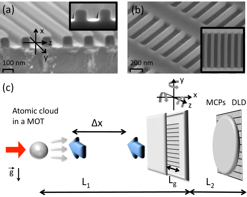
Transmission gratings etched into a 100 nm thick silicon nitride (Si3N4) membrane are commonly made using achromatic interferometric lithography Savas1995 using UV light, resulting in gratings with pitch down to 100 nm covering areas of several mm2. For its versatility in nanograting design, we chose electron beam lithography to pattern a new generation of resists with high selectivity during etching and low line edge roughness Thoms2014 . A 200 nm-period transmission nanograting has been fabricated on a 100 nm thick membrane of mm2 in size. The combination of 100 keV e-beam lithography and anisotropic reactive ion etching ensures parallel walls with deviations smaller than 0.5 degrees from the vertical Kruckel2017 ; Kaspar2010 ; SuppMat . The SEM image of a cleaved nanograting shows smooth and anisotropically etched walls, rounded with a 21 nm radius of curvature along the atom propagation axis [Fig. 1(a) and inset]. Statistical analysis of SEM images reveals a slotted hole geometry of the slits (with straight section along 90% of the total slit length), with a main width nm and a FWHM distribution of 7 nm [Fig. 1(b)].
Hybrid experiments at the interface between atomic physics and nanoscience often use alkali atoms for convenient laser cooling and manipulation. However, nanostructures chemically react with residual vapor that alters the CP potential unpredictably McGuirk2004 . Using noble gas atoms in a metastable state prevents chemical damage on nanostructures while retaining the ability for laser manipulation. The (), metastable state of argon is used for an efficient and accurate time-position detection by microchannel plates with 80 mm diameter in front of a delay line detector (DLD80 from RoentDek Handels GmbH). The experiment starts with a supersonic beam of argon followed by a counterpropagating electron gun, which provides a flux of Ar∗ atoms per second. The cycling transition () () (with MHz, nm) is used by a Zeeman decelerator to trap atoms in a magneto-optical trap (MOT). The trap consists of anti-Helmholtz coils providing the magnetic field and three retroreflected laser beams, red-detuned by 2, with 7 mW total power and 2.54 cm beam diameter. Approximately atoms are trapped at a temperature of mK.
An initial pulse sequence pushes an atom cloud at a chosen velocity orthogonally to the incoming supersonic beam at 13 Hz repetition rate Taillandier2016 . During this time, the magnetic field remains constant and the molasses laser beams are switched off. Simultaneously, the circularly polarized pushing laser beam (5 mW, frequency adjustable on the same cycling transition) is turned on for 0.4 ms toward the detector and focused to 20 cm after the MOT position. Atoms remain in the state without any influence on the diffraction process. A TOF measurement is then performed, with the time-position detector 86.8 cm away from the MOT. With this pushing technique, the relative spread of the atomic velocity distribution, , is already less than 10%. Moreover, a time selection of 1 ms is applied to obtain an even narrower velocity distribution. Additionally, for an absolute velocity determination, we used a light chopper with two resonant lasers of 1 mm diameter perpendicular to the atomic beam axis, separated by mm and time triggered with a time sequence accuracy below 50 s. We obtained mean velocities and respective uncertainties of ms-1 and ms-1 for both recorded spectra.
The vertical axis [see Fig. 1(c)] has been chosen for the slit alignment in order to impose a diffraction expansion perpendicular to the Earth’s gravitational field. At 56 cm from the MOT, the atomic beam diameter is much larger ( cm) than the entire nanograting surface and all slits along the axis contribute equally to the signal. This is not the case along the axis (diffraction axis) where the angular beam distribution acts as an incoherent source and smears the signal out, in particular interference orders that are separated by more than 2.6 (1.9) mrad for 19.1 (26.2) ms-1 . A compromise between atomic flux through the nanograting and fringe visibility (smearing) is achieved with a free opening of m between the vertical edge of the plate and the nanograting boundary. The atomic beam divergence, , through the 306 m slit at a distance from the MOT fits a Gaussian profile with 1.4 mrad FWHM. As a consequence, the beam divergence alters perceptibly the measured diffraction spectra, but in a controlled way. The nanograting is fixed on a 6D piezo system (SmarPod 11.45 from SmarAct GmbH) to ensure a degree angle between the atomic beam and the axis on the nanograting. An angular deviation as small as 0.2 degrees introduces noticeable asymmetry of the intensities of the diffraction orders.
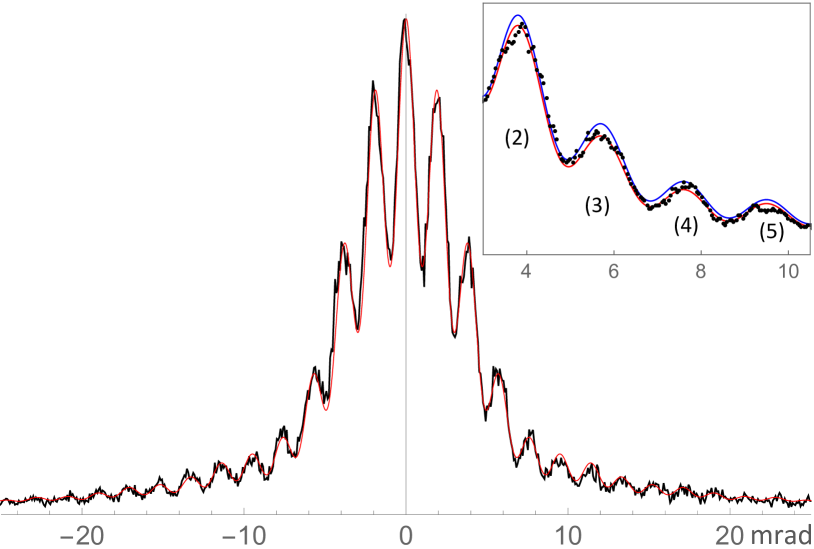
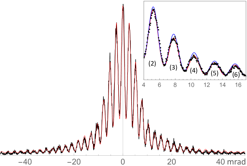
Two experimental diffraction spectra are shown in Fig. 2 for contributing velocities between ms-1 and ms-1 . Small electronic aberrations in position have been corrected by the use of a 2600-hole grid pattern, and no intensity inhomogeneity has been noticed at the experimental accuracy level. The recording times were 40 and 13 hours for and atoms, respectively. In general, for matter waves propagating through a transmission grating, the diffraction spectrum envelope is determined by the wavelength and the single slit width, while the interference peak visibility stems from the transverse coherence length of the source. In the present situation, the nanograting slit width effectively narrows due to atoms that are close enough to a surface being mechanically attracted and deflected by the Casimir–Polder potential. Metastable atoms colliding with the surface at room temperature are scattered randomly at high velocity, and will return to their ground state Hagstrum1954 .
For atoms at thermal velocities, the region near the surfaces the atoms needed to avoid was assumed to be a few nanometers Grisenti1999 ; Lonij2009 . Using classical trajectories, we can estimate a lower limit for the distance at which the atoms can pass the nanobars to be nm at a beam velocity of ms-1 or, equivalently, an effective slit width of nm. Such a major reduction cannot be neglected when explaining experimental diffraction spectra ( mrad at 19.1 ms-1 ). The effective slit width and the exerted CP forces elsewhere in the grating explain the overall broadening of the spectra compared with an equivalent optical picture with first zeros at 5 mrad. The fringe visibility depends only on the transverse coherence length of the atomic beam, , with the diameter of the incoherent source, as given by the van Cittert–Zernike theorem Born . However, the quadratic dispersion relation for matter waves suppresses the dephasing compared with light Taylor1994 , and hence enlarges . From the cloud size in the MOT, m, followed by thermal expansion, one finds () nm at 19.1 (26.2) ms-1 beam velocity.
The Huygens-Kirchhoff principle can be utilized for atoms propagating in a potential that is small compared with their kinetic energy Feynman1948 ; Kholodenko2018 . This can be justified with the help of the effective slit approximation, which removes atoms with potential energies that are too large. Additionally, the detection in the far field validates the Fraunhofer approximation (), in which the diffraction pattern results from the sum of wave path differences at the nanograting output. The CP potential is included in the wave propagation as an additional phase that depends on the atom-surface distance inside the nanograting slit . In short, the total phase can be written as for a detection angle and a wave number . The incoming Gaussian wave packets have a standard deviation Zecca2007 ; Thompson1957 . The experimental value for covers up to seven slits coherently and hence, the beam cannot be considered as a plane wave. The diffraction intensity then reads as
| (1) |
In eikonal approximation, the phase shift imprinted by a potential is the integral of the potential along the particle trajectory Landau . Neglecting the surface potential outside the grating, one finds
| (2) |
where nm is the nanograting depth and the beam velocity. However, it is necessary to account for the exact shape of the grating along the axis, because the slit widths increase near the output. We incorporate this effect by using a smaller slit thickness of nm.
In pioneering experiments with nanogratings and supersonic beams Grisenti1999 ; Perreault2005 , the CP potential is modeled in the nonretarded regime as for the two adjacent surfaces. Semi-infinite surfaces are implicitly considered everywhere inside the grating even if this is not correct near the edges. Further, the effect of multiple reflection from the bar opposite has been neglected Dutier2003 . These approximations are justified for fast atoms or molecules as the overall phase shift remains small on average Brand2015 . In the nonretarded regime, the coefficient is given by the Lifshitz formula Lifshitz1958 ; Mavroyannis1963
| (3) |
where denotes the atomic dynamic polarizability, and is the surface permittivity taken at imaginary frequencies . For metastable argon in the state, we obtain a.u., or 5.04 meV nm3 in front of a Si3N4 surface with spectral responses in the UV and IR Philipp1973 . An estimate of the uncertainty of this value is rather difficult to obtain. First, the material may show imperfections with regard to its fabrication and size Zollner2001 that alter the index of refraction. Second, the electronic structure of argon in the metastable state, due to its 11.5 eV internal energy, makes the potential more sensitive to the material optical response in the visible and near-UV regions, where accurate optical response data are difficult to obtain. Third, the electronic core contribution has been estimated to be in the range of 0.03 a.u. using the first ionic state. Such a small core contribution is a clear theoretical advantage of metastable argon compared with heavier (alkali) atoms Derevianko1999 . The temperature dependence of can be safely neglected here, in contrast to situations in which dominant transitions appear in the mid-IR region Laliotis2014 . Altogether, we conservatively estimate a 10% uncertainty that is similar to other CP calculations.
The improvement in experimental accuracy allows us to discern the nonretarded regime and the onset of retardation effects, that arise due to the finite field propagation time between atom and surface. This effect becomes relevant at distances larger than . Without resorting to a full calculation of the exact shape of the potential, one can resort to sophisticated interpolations. Here, we use a model derived in Ref. Wylie that is built on a single atomic transition (here, nm for Ar ), for which the effective coefficient reads as
| (4) |
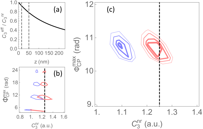
with and given in f1f2 . This expression provides an interpolation between at short distances and for . Inside the grating, goes from at to [Fig. 3(a)]. On average, the detected atoms will have experienced , which corresponds to a 15% deviation from the nonretarded regime. This model is in very good agreement with the complete QED calculation Scheel2008 to within a few percent for semi-infinite surfaces, and arguably much faster to calculate.
As first shown in Ref. Lonij2009 , the fitting procedure is extremely sensitive to the grating geometry, and there is no unique relation between the experimental spectrum and the set of possible theoretical parameters. A chi-squared test is used with , where , and are the experimental noise standard deviation, and the experimental and theoretical intensities at the angle , respectively. Indeed, we find a linear relation between and slit width as well as nanograting thickness to within 10% of their nominal values: 1 nm 0.07 a.u. and nm a.u. On the other hand, and are not linked to any other parameters. The remaining important parameter, in Eq. (1), is the maximum additional CP phase shift with . Note that is different for both models as increases with larger . Also, at larger velocities this parameter was not considered to be critical Bender2010 .
With this, Figure 3(b) shows () surfaces of and at a beam velocity of ms-1 and where is the standard deviation for two parameters numrec . The chosen magnification of 40 reveals four local minima for that have previously not been discussed, but which are necessary for a correct analysis using the Kirchhoff approximation. They correspond, respectively, to distances nm from the surface. We chose the global minimum for further discussion given by rad. The dashed line is the calculated expected . Figure 3(c) is an enlargement of Fig. 3(b) for 1 standard deviation that rejects the van der Waals approximation (blue) by more than with regard to the calculated . In addition, minima for both velocities are found to be smaller with the full CP model. For further clarity, the insets in Fig. 2 emphasize the influence of both models on the spectra calculated at rad with the theoretically expected . Our extracted value of a.u. is strongly dominated by grating geometry uncertainties ( a.u.), where statistical error bars – assuming a known grating – represent only % ( a.u.) at one . Such an unprecedented value is clearly connected to the ultra large diffraction spectra broadening. Note that it corrects the rather crude approximation given in Ref. Karam2005 .
The advantage of using a slow atomic beam with a well-defined velocity rather than a thermal beam derives from the fact that the atom-surface interaction potential can be probed to a much higher accuracy. However, this presents another difficulty: the Kirchhoff approximation stipulates that the (change of the) transverse wave number has to be small compared with the longitudinal wave number, Arsenovic2005 . The slower the atoms become, the more (relative) transverse momentum they accumulate whilst traversing the grating. At the cutoff that determines the effective slit width, we can estimate the relative change in transverse wave number to be roughly 5% for a beam velocity of ms-1 , but already 10% for a velocity of ms-1 . This implies that the Kirchhoff approximation can no longer be relied upon at slower beam velocities, at which a more detailed theoretical description is required.
In conclusion, we have demonstrated the importance of the retarded Casimir-Polder potential for the diffraction of metastable Ar in a range of atom-surface distances as small as nm with a Si3N4 transmission nanograting. Because of atomic velocities as slow as 19.1 ms-1 as well as an accurate geometrical characterization of the nanograting, we were able to discriminate a difference in the CP potential as small as 15%. For lower velocities or smaller slit widths, the semiclassical model utilized for the simulations should be replaced by a quantum mechanical model. Such a theoretical refinement will introduce quantum reflexion at the slit walls and may produce, in some geometry, gravity Q-bounces as found for neutrons Jenke2011 . This Letter opens the opportunity for unprecedented and accurate CP potential measurements by controlling the tilt of the nanograting, which, combined with tomography methods, would lead to a thorough understanding of atom-surface interactions with implications for theoretical physics as well as nanometrology. For example, the hypothetical non-Newtonian fifth force Antoniadis2011 could be constrained by an atomic physics experiment. Atomic quantum random walks Karski2009 based on multipath beam splitters can be simply realized with two or more nanogratings, and closed-loop interferometers can be made extraordinary compact.
Acknowledgements.
The authors from Laboratoire de Physique des Lasers acknowledge the ”Institut Francilien de Recherche sur les Atomes Froids” (IFRAF) for supports. This work has been supported by Region Ile-de-France in the framework of DIM SIRTEQ. The work was partly supported by the French Renatech network. The authors acknowledge B. Darquié for fruitful data analysis discussions.References
- (1) H.B.G. Casimir and D. Polder, The influence of retardation on the London-van der Waals forces, Phys. Rev. 73, 360 (1948).
- (2) S. Scheel and S. Y. Buhmann, Macroscopic quantum electrodynamics – concepts and applications, Acta Phys. Slovaca 58, 675 (2008).
- (3) S. Y. Buhmann, Dispersion Forces I – Macroscopic Quantum Electrodynamics and ground-state Casimir, Casimir–Polder and van der Waals forces (Springer, Berlin, 2012).
- (4) H.B.G. Casimir, On the Attraction between Two Perfectly Conducting Plates, Proc. Kon. Ned. Akad. Wet. 51, 793 (1948).
- (5) U. Mohideen and A. Roy, Precision Measurement of the Casimir Force from 0.1 to 0.9 m, Phys. Rev. Lett. 81, 4549 (1998).
- (6) F. Intravaia, et al., Strong Casimir force reduction through metallic surface nanostructuring, Nat. Commun. 4, 2515 (2013).
- (7) V. Sandoghdar, C.I. Sukenik, E.A. Hinds, and S. Haroche, Direct measurement of the van der Waals interaction between an atom and its images in a micron-sized cavity, Phys. Rev. Lett. 68, 3432 (1992).
- (8) C. I. Sukenik, M. G. Boshier, D. Cho, V. Sandoghdar, and E. A. Hinds, Measurement of the Casimir–Polder force, Phys. Rev. Lett. 70, 560 (1993).
- (9) A. Landragin , J.-Y. Courtois, G. Labeyrie, N. Vansteenkiste, C. I. Westbrook and A. Aspect, Measurement of the van der Waals Force in an Atomic Mirror, Phys. Rev. Lett. 77, 1464 (1996).
- (10) F. Shimizu, Specular Reflection of Very Slow Metastable Neon Atoms from a Solid Surface, Phys. Rev. Lett. 86, 987 (2001).
- (11) H. Bender, Ph. W. Courteille, C. Marzok, C. Zimmermann, and S. Slama, Direct Measurement of Intermediate-Range Casimir-Polder Potentials, Phys. Rev. Lett. 104, 083201 (2010).
- (12) R. E. Grisenti, W. Schöllkopf, J. P. Toennies, G. C. Hegerfeldt, and T. Köhler, Determination of Atom-Surface van der Waals Potentials from Transmission-Grating Diffraction Intensities, Phys. Rev. Lett. 83, 1755 (1999); R. Brühl, P. Fouquet, R. E. Grisenti, J. P. Toennies, G. C. Hegerfeldt, T. Köhler, M. Stoll, and C. Walter, The van der Waals potential between metastable atoms and solid surfaces: Novel diffraction experiments vs. theory, Europhys. Lett. 59, 357 (2002).
- (13) V. P. A. Lonij, W. F. Holmgren, and A. D. Cronin, Magic ratio of window width to grating period for van der Waals potential measurements using material gratings, Phys. Rev. A 80, 062904 (2009).
- (14) M. Fichet, G. Dutier, A. Yarovitsky, P. Todorov, I. Hamdi, I. Maurin, S. Saltiel, D. Sarkisyan, M.-P. Gorza, D. Bloch, and M. Ducloy, Exploring the van der Waals atom-surface attraction in the nanometric range, Europhys. Lett. 77, 54001 (2007).
- (15) S. Nimmrichter and K. Hornberger, Theory of near-field matter-wave interference beyond the eikonal approximation, Phys. Rev. A 78, 023612 (2008).
- (16) T. A. Savas, S. N. Shah, M. L. Schattenburg, J. M. Carter, and H. I. Smith, Achromatic interferometric lithography for 100-nm-period gratings and grids, J. Vac. Sci. Technol. B 13, 2732 (1995); T. A. Savas, M. L. Schattenburg, J. M. Carter, and H. I. Smith, Large-area achromatic interferometric lithography for 100 nm period gratings and grids, J. Vac. Sci. Technol. B 14, 4167 (1996).
- (17) S. Thoms and D. S. Macintyre, Investigation of CSAR 62, a new resist for electron beam lithography, J. Vac. Sci. Technol B 32, 06FJ01 (2014).
- (18) Clemens J. Krückel, Attila Fülöp, Zhichao Ye, Peter A. Andrekson, and Victor Torres-Company, Optical bandgap engineering in nonlinear silicon nitride waveguides, Opt. Express 25, 15370 (2017).
- (19) P. Kaspar, Y. Jeyaram, H. Jäckel, A. Foelske, R. Kötz, and S. Bellini, Silicon nitride hardmask fabrication using a cyclic CHF3-based reactive ion etching process for vertical profile nanostructures, J. Vac. Sci. Technol B 28(6) (2010).
- (20) See Supplemental Material [url] for details, which includes Refs.Thoms2014 ; Kruckel2017 ; Kaspar2010
- (21) J. M. McGuirk, D. M. Harber, J. M. Obrecht, and E. A. Cornell, Alkali-metal adsorbate polarization on conducting and insulating surfaces probed with Bose-Einstein condensates, Phys. Rev. A 69, 062905 (2004).
- (22) T. Taillandier-Loize et al., A simple velocity-tunable pulsed atomic source of slow metastable argon, J. Phys. D: Appl. Phys. 49, 135503 (2016).
- (23) H. D. Hagstrum, Theory of Auger ejection of electron from metal by ions, Phys. Rev. 96, 336 (1954).
- (24) A. Laliotis, T. Passerat De Silans, I. Maurin, M. Ducloy, and D. Bloch, Casimir-Polder interactions in the presence of thermally excited surface modes, Nat. Commun. 5, 4364 (2014).
- (25) M. Born and E. Wolf, Principles of optics, 4th. ed. (Pergamon Press, 1970).
- (26) B. Taylor, K.J. Schernthanner, G. Lenz, and P. Meystre, The van Cittert-Zernike theorem in atom optics, Opt. Commum. 110, 569 (1994).
- (27) R. Feynman, Space-Time Approach to Non-Relativistic Quantum Mechanics, Rev. Mod. Phys. 20, 367 (1948).
- (28) A. L. Kholodenko and L. H. Kauffman, Huygens triviality of the time-independent Schrödinger equation. Applications to atomic and high energy physics, Ann. Phys. 390, 1 (2018).
- (29) A. Zecca, Double Slit Diffraction Pattern of Gaussian Wave Packet Interacting with the Wall, Adv. Studies Theor. Phys. 1, 539 (2007). http://www.m-hikari.com/astp/astp2007/astp9-12-2007/zeccaASTP9-12-2007.pdf
- (30) B. J. Thompson and E. Wolf, Two-Beam Interference with Partially Coherent Light, J. Opt. Soc. Am. 47, 895 (1957).
- (31) L. Landau and E. Lifchitz, Quantum Mechanics: Non-Relativistic Theory, 3th. ed. (Pergamon Press, 1974).
- (32) J. D. Perreault and A. D. Cronin, Observation of Atom Wave Phase Shifts Induced by Van Der Waals Atom-Surface Interactions, Phys. Rev. Lett. 95, 133201 (2005).
- (33) G. Dutier, S. Saltiel, D. Bloch, and M. Ducloy, Revisiting optical spectroscopy in a thin vapor cell: mixing of reflection and transmission as a Fabry?Perot microcavity effect, J. Opt. Soc. Am. B 20, 793 (2003).
- (34) C. Brand, J. Fiedler, T. Juffmann, M. Sclafani, C. Knobloch, S. Scheel, Y. Lilach, O. Cheshnovsky, and M. Arndt, A Green’s function approach to modeling molecular diffraction in the limit of ultra-thin gratings, Ann. Phys. 527, 580 (2015).
- (35) S. Zollner and E. Apen, Optical Constants for Metrology of Hydrogenated Amorphous Silicon-Nitrogen Alloys on Si, AIP Conference Proceedings 550, 532 (2001); C. J. Krückel, A. Fülöp, Z. Ye, P. A. Andrekson, and V. Torres-Company, Optical bandgap engineering in nonlinear silicon nitride waveguides, Opt. Exp. 25, 15370 (2017).
- (36) H. R. Philipp, Optical Properties of SiliconNitride, J. Electrochem. Soc. 120, 295 (1973); K. Luke, Y. Okawachi, M. R. E. Lamont, A. L. Gaeta, and M. Lipson, Broadband mid-infrared frequency comb generation in a Si3N4 microresonator, Opt. Lett. 40, 4823 (2015).
- (37) E. M. Lifshitz, The theory of molecular attractive forces between solids, Sov. Phys. JETP, 2, 73 (1956).
- (38) C. Mavroyannis, The interaction of neutral molecules with dielectric surfaces, Mol. Phys. 6, 593 (1963).
- (39) A. Derevianko, W. R. Johnson, M. S. Safronova and J. F. Babb, High-Precision Calculations of Dispersion Coefficients, Static Dipole Polarizabilities, and Atom-Wall Interaction Constants for Alkali-Metal Atoms, Phys. Rev. Lett. 82, 3589 (1999); A. D. Cronin and J. D. Perreault, de Broglie Wave Phase Shifts Induced by Surfaces Closer than 25 nm, J. Phys.: Conf. Series 19, 48 (2005).
- (40) J. M. Wylie and J. E. Sipe, Quantum electrodynamics near an interface, Phys. Rev. A 30, 1185 (1984).
- (41) and where and are the integral cosine and sine functions
- (42) W. H. Press, S. Teukolsky, W. Vetterling, and B. Flannery, Numerical Recipes (Cambridge University Press, Cambridge, 2007)
- (43) J.-C. Karam, N. Wipf, J. Grucker, F. Perales, M. Boustimi, G. Vassilev, V. Bocvarski, C. Mainos, J. Baudon, and J. Robert, Atom diffraction with a ’natural’ metastable atom nozzle beam, J. Phys. B: At. Mol. Opt. Phys. 38, 2691 (2005).
- (44) D. Arsenović, M. Božić, O. V. Man’ko, and V. I. Man’ko, Equivalence of two forms of the solution to the Schrödinger equation for a particle passing through a grating, J. of Russian Laser Res. 26, 94 (2005).
- (45) T. Jenke, P. Geltenbort, H. Lemmel, and H. Abele, Realization of a gravity-resonance-spectroscopy technique, Nat. Phys. 7, 468 (2011).
- (46) I. Antoniadis et al., Short-range fundamental forces, C. R. Physique 12, 755 (2011).
- (47) M. Karski, L. Förster, J-M. Choi, A. Steffen, W. Alt, D. Meschede and A. Widera, ”Quantum Walk in Position Space with Single Optically Trapped Atoms”, Science 325 174 (2009)