Engineering atomic polarization with microwave-assisted optical pumping
Abstract
Polarized atomic ensembles play a crucial role in precision measurements. We demonstrate a novel method of creating atomic polarization in an alkali vapor in a continuous-wave regime. The method relies on a combination of optical pumping by a laser beam and microwave transitions due to a cavity-enhanced magnetic field. With this approach, atomic internal angular momentum can be oriented along a static magnetic field at an arbitrary angle with respect to the laser beam. Furthermore, the atomic polarization depends on the microwave parameters, which can be used for microwave-to-optical transduction and microwave-controlled nonlinear magneto-optical rotation.
Throughout atomic physics, the light-matter interaction is used to control quantum states of matter, with results that range from revealing fundamental physics [1] to enabling precision timekeeping [2]. The advent of the laser meant that the electric-dipole transitions (with their stronger couplings) could be readily accessed and precisely controlled within the atom. In parallel, microwave transitions, enabled by the weaker magnetic-dipole interactions such as in the “clock” transitions between hyperfine ground states of alkali metal vapours, can be independently and simultaneously manipulate atomic states, providing a path towards a microwave-to-optical interface using atomic media [3].
As a platform for quantum technologies, alkali-metal atomic ensembles, which naturally support microwave and optical transitions, provide a good opportunity for microwave-to-optical quantum transduction [4, 5, 6, 7, 8, 9] and for storing and retrieving quantum information on demand [10, 11, 12]. The nonlinear effects of microwave interactions on optical properties of alkali vapors also include the transduction of classical signals [13, 14, 15, 16, 17, 18, 19, 20, 21, 22, 23], compact atomic clocks [24, 25, 26], microwave electrometry [27], and static and microwave magnetometry [28, 29, 30, 31, 32].
In many cases, the microwave’s effect on the optical properties in atomic vapors is due to atomic polarization: a particular distribution of the atoms in the ensemble among the available quantum states, which generally have well-defined angular momenta or “spin,” allowing for the definition of a direction along which the polarization points and the equivalent nomenclature of a spin polarization. Polarized atomic ensembles like these are essential components of optically pumped atomic magnetometers [33, 34, 35, 36, 37]; indeed, some approaches require atomic polarization to be perpendicular to the probe laser beam [33, 35], which is non-trivial task for a single-laser setup [38].
In this Letter, we introduce a novel technique for engineering spin polarization in atomic ensembles based on microwave-assisted optical pumping (MAOP). MAOP can be understood as an extension of microwave-optical double-resonance and similar to optically detected magnetic resonance (ODMR) methods in solid-state systems [39, 40], except here, at least one of the two ground-state levels requires several sublevels [Fig. 1]. MAOP leads to an uneven distribution of atomic populations, resulting in atomic polarization . We observe this polarization as a microwave-induced optical birefringence and dichroism. The dichroism can be used to implement a polarization-selective microwave-to-optical interface, while the birefrengince leads to microwave-controlled nonlinear magneto-optical rotation [41] that can be applied for signal transduction based on pulse carving [42].
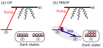
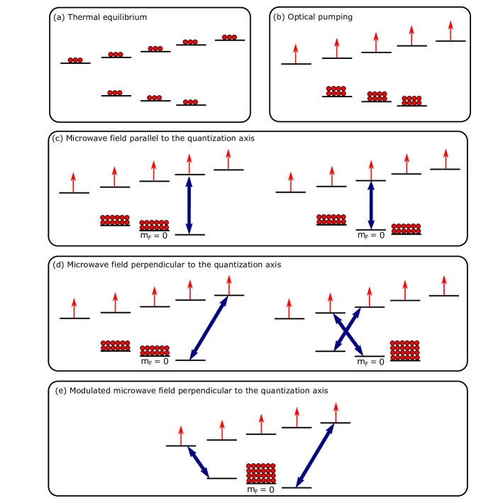
The atomic polarization emerging from MAOP results from the particular configuration of dark states that emerge in the presence of combined optical and microwave fields. To illustrate this principle, consider a four-level toy model shown in Fig. 1. Here, an optical field (“pump”) couples ground level to excited level [Fig. 1(a)]. Ground states and are separated from state by a microwave magnetic-dipole transition. We assume that the frequency separation is sufficient to make optical excitation of and by the pump field negligible, rendering both states “dark.” Additionally assuming that there is no relaxation between the ground state when this system interacts only with the optical field, optical pumping transfers the atomic population into the dark states and . When an additional microwave field couples states and , remains dark and the atomic population accumulates here [Fig. 1(b)], thus polarizing the ensemble.
In our experiment, we observe MAOP in thermal 87Rb vapor, which is contained by a vapor cell enclosed in a microwave cavity [Fig. 2(a)]. We use the TE011 cavity mode tuned to the ground-state hyperfine transition at GHz. The cavity quality factor for this mode is . The microwave field is provided by a microwave source, with a power of 100 W at the source output, without additional amplification. The cavity has a pair of holes providing optical access for the pump and probe laser beams. The pump and probe beams are provided by two different lasers. For the optical pumping we use transition [Fig. 2(b)] within the D2 line at around nm with a typical laser power of mW.
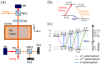
For the probe, we use a typical power between W, and we set its frequency according to the particular measurement: in the absorptive regime, it is resonant with transition of the D2 line, and in the dispersive case, the probe is red-detuned from this transition. The counterpropagating probe and pump beams are overlapped inside the cell (Fig. 2a). We use a wave plate (WP) (either a quarter-wave plate or a half-wave plate) to control the probe polarization as it enters the cell. To analyze the MAOP effect on the probe polarization, a polarizing beamsplitter (PBS2) splits the probe between two photodetectors (PD1 and PD2). The static magnetic field inside the cell is controlled by three pairs of Helmholtz coils along mutually perpendicular axes.
The 87Rb ground state has nine possible microwave transitions [Fig. 2(c)] with three different polarizations: , , and . A static magnetic field inside the cell affects both the frequency difference between the microwave transitions and the strength of transitions corresponding to a particular polarization of the microwave field. The magnitudes of the static magnetic fields in our experiment are within the regime of the linear Zeeman effect, giving the frequency separation between two neighbouring transitions by the Larmor frequency , where is the Bohr magneton and is the reduced Planck constant. Some of the transitions are shifted by the same frequency, giving two pairs of degenerate transitions. The typical values of the Larmor frequency in our experiments are on the order of kHz, which is much less than the width of the D2 line (on the order of MHz), meaning that both probe and pump couple to all Zeeman sublevels of the corresponding hyperfine levels simultaneously. We define the quantization axis as parallel to , so the polarization of the microwave field with respect to the quantization axis is determined by the angle between the microwave magnetic field vector and . Here, the transitions correspond to the microwave vector component parallel to , while transitions correspond to the microwave vector orthogonal to . In our setup, the microwave field vector is parallel to the cavity axis, which is fixed, so we control the microwave polarization with respect to the quantization axis by rotating with the Helmholtz coils.
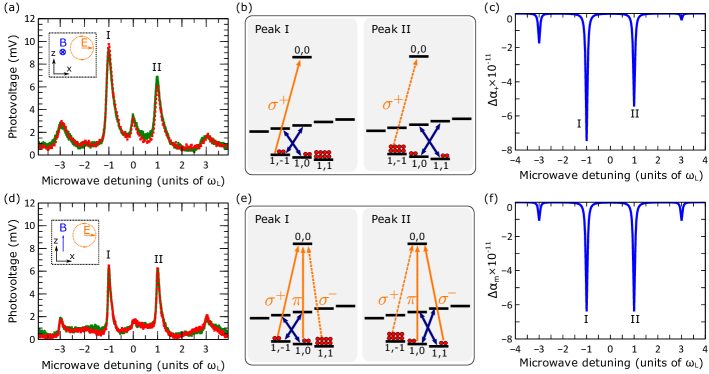
Absorption. We begin with MAOP measurements in absorptive regime [Fig. 3]. For these measurements, the probe is circularly polarized with respect to its wavevector, in which case the probe power splits equally between the two photodetectors. Fig. 3(a) shows the AC part of the photovoltages from both detectors during a linear microwave frequency scan when is parallel to the probe wavevector. In this case, the probe is -polarized with respect to the quantization axis, while the microwave field, whose vector is orthogonal to , is an equal superposition of and polarizations. As we scan the microwave frequency, we see an increase in the probe transmission whenever the microwave is on resonance with a transition allowed by the microwave polarization. The asymmetry in the signal in Fig. 3(a) results from the fact the microwave field creates different atomic polarizations at different frequencies. Fig. 3(b) illustrates the population distribution for peaks I and II obtained with corresponding to opposite values of the microwave detuning with respect to the clock transition . In the first case, the microwave field simultaneously drives and , in which case the MAOP transfers the atomic population to . Because only the transition is allowed for a probe, its transmission is increased due to the reduced population of . In the case of peak II, the MAOP moves the atomic population to , where the probe can be absorbed, making the observed transmission smaller than in the first case. If we reverse the bias field direction, the asymmetry of the observed signal is reversed (not shown) since in this case probe is polarized and it is absorbed more strongly when the atomic population is transferred to .
Note that the simplified concept of MAOP introduced in Fig. 1 does not fully explain the signals observed in Fig. 3(a). For example, instead of peak II, we would expect to see a dip in the optical transmission since the atomic polarization, in this case, provides a higher optical density compared to an unpolarized atomic ensemble. To resolve this, we introduced a comprehensive theoretical model describing MAOP in an ensemble with thermal relaxation [43]. It also includes the contribution to the absorption from the velocity classes resonant with and transitions due to the Doppler effect. With this model, we calculate the steady-state optical absorption in terms of parameter , where denotes the particular probe polarization. Parameter is proportional to the absorption, and it captures the qualitative dependence on the microwave field characteristics. Fig. 3(c) shows the absorption coefficient calculated for an ensemble dominated by thermal relaxation between the ground-state levels, and it is in a good agreement with the observed signal.
To confirm that the direction of the atomic polarization is defined by the bias magnetic field vector, we perform the same measurement with the bias field applied out-of-page () [Fig. 3(d-e)], in which case, it is perpendicular to both the microwave magnetic field and the probe wave vector. While the microwave field is still polarized, the probe polarization now has components parallel and orthogonal to the quantization field and couples to all three sublevels of the lower-energy ground state. Because the probe power is divided equally between and polarization components, the atomic polarizations corresponding to opposite microwave detunings have the same effect on optical absorption, and so the observed signal is symmetric.
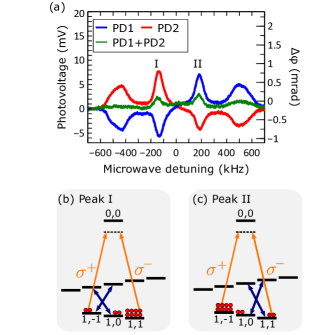
To further demonstrate the emergence of atomic polarization due to the microwave field, we explore effects in the dispersive regime. In this case, the MAOP induced atomic polarization leads to circular birefringence, resulting in the rotation of the probe polarization. To observe the optical rotation, we use a linearly polarized probe whose frequency is set to the lower-frequency edge of the Doppler-broadened absorption peak of the D2-line originating in the level. In this case, the probe is red-detuned from the transition to the extent where its absorption is reduced and the dispersion is enhanced compared to the resonant case. In addition, and resonant classes experience an even higher detuning, and their contribution to the total signal is reduced. With a half-wave plate, we set the probe polarization at with respect to the -axis ( with respect to the -axis), in which case PBS2 splits the probe power equally between the two photodetectors. In this setup, the optical rotation will result in opposite changes in the photovoltage of the two detectors without affecting the total optical power. The bias magnetic field is applied parallel to the probe, so the probe electric-field vector with respect to the quantization axis is an equal superposition of - and -polarized fields.
The optical rotation is a result of circular birefringence due to unbalanced populations of states and . Assuming that the single-atom refraction index is the same for each transition, the effective refractive index for each transition is proportional to the population at the corresponding level. As a result, the phase difference between the two polarization components leaving the ensemble is given by
| (1) |
where is the wavenumber, and the distance through which the light travels in the medium, is the single-atom refraction index, and and are the numbers of atoms in states and states, respectively. This phase difference determines the angle by which the linear optical polarization is rotated.
Fig. 4(a) shows the relative photovoltage from PD1 and PD2 measured in the dispersive regime during a linear sweep of the microwave frequency. Whenever the microwave field is on resonance with an allowed hyperfine transition, it results in opposite voltage changes on the two detectors, indicating the optical rotation. The sum of the two voltages is small but not exactly zero, which indicates that some part of the signal corresponds to the absorptive regime. The fact that the signal from each detector is antisymmetric with respect to the clock-transition frequency means that the direction of the polarization rotation depends on the sign of the microwave detuning. According to Eq. 1, this is a consequence of a change in the sign of the population difference between levels and , and thus a change in the “direction” of the atomic polarization. Fig. 4(b) schematically shows the population distribution for peaks I and II from Fig. 4(a). Due to a higher population of in the case of negative microwave detuning, the -polarization component experiences a larger refractive index and acquires a phase delay relative to the -polarization component, so the linear polarization rotates towards the horizontal axis, and more optical power goes to PD2. For the positive microwave detuning, the population is transferred to , so the component is delayed, and the rotation direction is reversed. If we turn off the pump light or set its frequency off-resonance, the observed signal feature disappears, which suggests that the observed circular birefringence of the vapor results from MAOP and not from the non-linear interaction between the microwave field and the probe itself. We also highlight that when the microwave field is not on resonance with any transition, no optical rotation is observed.
Finally, we emphasize that the optical rotation due to polarization of atomic vapor discussed above corresponds to paramagnetic Faraday rotation [44], which differs from diamagnetic Faraday rotation, where the optical rotation angle is proportional to the magnitude of a strong static magnetic field applied parallel to the optical beam [45]. In the case of diamagnetic Faraday rotation, transitions corresponding to different circular polarizations experience different frequency shifts due to the interaction with the static magnetic field leading to the circular birefringence.
To summarize, we introduced the technique of microwave-assisted optical pumping, which enables atomic-spin polarization engineering by combining microwave magnetic-dipole transitions with optical pumping. We demonstrated that the engineered atomic-spin polarization depends on the microwave frequency by observing its effect on optical circular birefringence and dichroism in a thermal atomic vapor in the dispersive and absorptive regimes, respectively. While the current experiments were performed in a thermal atomic vapor, and we expect better performance in cold ensembles, where collisional and spin-exchange relaxation between the ground-state levels is reduced. By engineering atomic polarization engineering via MAOP-tailored optical absorption and dispersion, we have demonstrated a suite of techniques for domain of microwave-to-optical control [3], including possibilities for a microwave-controlled polarization-selective optical switch that could encode polarization states of light, where applying a microwave field makes the atomic vapor transparent for light with a particular polarization, with applications to microwave-to-optical transduction.
Acknowledgements
This work was supported by the University of Alberta; the Natural Sciences and Engineering Research Council, Canada (Grants No. RGPIN-04523-16, No. RGPIN-2021-02884, and No. CREATE-495446-17); the Alberta Quantum Major Innovation Fund; Alberta Innovates; and the Canada Research Chairs (CRC) Program. As researchers at the University of Alberta, we acknowledge that we are located on Treaty 6 territory, and that we respect the histories, languages, and cultures of First Nations, Métis, Inuit, and all First Peoples of Canada, whose presence continues to enrich our vibrant community.
References
- Georgescu et al. [2014] I. M. Georgescu, S. Ashhab, and F. Nori, Quantum simulation, Rev. Mod. Phys. 86, 153 (2014).
- Ludlow et al. [2015] A. D. Ludlow, M. M. Boyd, J. Ye, E. Peik, and P. O. Schmidt, Optical atomic clocks, Rev. Mod. Phys. 87, 637 (2015).
- Lauk et al. [2020] N. Lauk, N. Sinclair, S. Barzanjeh, J. P. Covey, M. Saffman, M. Spiropulu, and C. Simon, Perspectives on quantum transduction, Quantum Sci. Technol. 5, 020501 (2020).
- Vewinger et al. [2007] F. Vewinger, J. Appel, E. Figueroa, and A. I. Lvovsky, Adiabatic frequency conversion of optical information in atomic vapor, Opt. Lett. 32, 2771 (2007).
- Gard et al. [2017] B. T. Gard, K. Jacobs, R. McDermott, and M. Saffman, Microwave-to-optical frequency conversion using a cesium atom coupled to a superconducting resonator, Phys. Rev. A 96, 013833 (2017).
- Han et al. [2018] J. Han, T. Vogt, C. Gross, D. Jaksch, M. Kiffner, and W. Li, Coherent Microwave-to-Optical Conversion via Six-Wave Mixing in Rydberg Atoms, Phys. Rev. Lett. 120, 093201 (2018).
- Vogt et al. [2019] T. Vogt, C. Gross, J. Han, S. B. Pal, M. Lam, M. Kiffner, and W. Li, Efficient microwave-to-optical conversion using Rydberg atoms, Phys. Rev. A 99, 023832 (2019).
- Liang et al. [2019] Z.-T. Liang, Q.-X. Lv, S.-C. Zhang, W.-T. Wu, Y.-X. Du, H. Yan, and S.-L. Zhu, Coherent Coupling between Microwave and Optical Fields via Cold Atoms *, Chinese Phys. Lett. 36, 080301 (2019).
- Liu et al. [2021] Y.-G. Liu, K. Xia, and S.-L. Zhu, Efficient microwave-to-optical single-photon conversion with a single flying circular Rydberg atom, Opt. Express 29, 9942 (2021).
- Zhang et al. [2009] R. Zhang, S. R. Garner, and L. V. Hau, Creation of Long-Term Coherent Optical Memory via Controlled Nonlinear Interactions in Bose-Einstein Condensates, Phys. Rev. Lett. 103, 233602 (2009).
- Katz and Firstenberg [2018] O. Katzand O. Firstenberg, Light storage for one second in room-temperature alkali vapor, Nat. Commun. 9, 2074 (2018).
- Saglamyurek et al. [2021] E. Saglamyurek, T. Hrushevskyi, A. Rastogi, L. W. Cooke, B. D. Smith, and L. J. LeBlanc, Storing short single-photon-level optical pulses in Bose-Einstein condensates for high-performance quantum memory, New J. Phys. 23, 043028 (2021).
- Cox et al. [2018] K. C. Cox, D. H. Meyer, F. K. Fatemi, and P. D. Kunz, Quantum-Limited Atomic Receiver in the Electrically Small Regime, Phys. Rev. Lett. 121, 110502 (2018).
- Deb and Kjærgaard [2018] A. B. Deband N. Kjærgaard, Radio-over-fiber using an optical antenna based on Rydberg states of atoms, Appl. Phys. Lett. 112, 211106 (2018).
- Anderson et al. [2021] D. A. Anderson, R. E. Sapiro, and G. Raithel, An Atomic Receiver for AM and FM Radio Communication, IEEE Trans. Antennas Propag. 69, 2455 (2021).
- Meyer et al. [2018] D. H. Meyer, K. C. Cox, F. K. Fatemi, and P. D. Kunz, Digital communication with Rydberg atoms and amplitude-modulated microwave fields, Appl. Phys. Lett. 112, 211108 (2018).
- Song et al. [2019] Z. Song, H. Liu, X. Liu, W. Zhang, H. Zou, J. Zhang, and J. Qu, Rydberg-atom-based digital communication using a continuously tunable radio-frequency carrier, Opt. Express 27, 8848 (2019).
- Jiao et al. [2019] Y. Jiao, X. Han, J. Fan, G. Raithel, J. Zhao, and S. Jia, Atom-based receiver for amplitude-modulated baseband signals in high-frequency radio communication, Appl. Phys. Express 12, 126002 (2019).
- Gordon et al. [2019] J. A. Gordon, M. T. Simons, A. H. Haddab, and C. L. Holloway, Weak electric-field detection with sub-1 Hz resolution at radio frequencies using a Rydberg atom-based mixer, AIP Adv. 9, 045030 (2019).
- Simons et al. [2019] M. T. Simons, A. H. Haddab, J. A. Gordon, and C. L. Holloway, A Rydberg atom-based mixer: Measuring the phase of a radio frequency wave, Appl. Phys. Lett. 114, 114101 (2019).
- Holloway et al. [2019] C. L. Holloway, M. T. Simons, A. H. Haddab, C. J. Williams, and M. W. Holloway, A real-time guitar recording using Rydberg atoms and electromagnetically induced transparency: Quantum physics meets music, AIP Adv. 9, 065110 (2019).
- Tretiakov et al. [2020] A. Tretiakov, C. A. Potts, T. S. Lee, M. J. Thiessen, J. P. Davis, and L. J. Leblanc, Atomic microwave-to-optical signal transduction via magnetic-field coupling in a resonant microwave cavity, Appl. Phys. Lett. 116, 164101 (2020).
- Li et al. [2021] C. Li, F. Sun, J. Liu, X. Li, D. Hou, and S. Zhang, Continuous microwave-to-optical transduction with atomic beam fluorescence, Appl. Phys. Lett. 119, 154001 (2021).
- Pétremand et al. [2012] Y. Pétremand, C. Affolderbach, R. Straessle, M. Pellaton, D. Briand, G. Mileti, and N. F. De Rooij, Microfabricated rubidium vapour cell with a thick glass core for small-scale atomic clock applications, J. Micromechanics Microengineering 22, 25013 (2012).
- Pellaton et al. [2012] M. Pellaton, C. Affolderbach, Y. Pétremand, N. De Rooij, and G. Mileti, Study of laser-pumped double-resonance clock signals using a microfabricated cell, Phys. Scr. T149, 14013 (2012).
- Bandi et al. [2014] T. Bandi, C. Affolderbach, C. Stefanucci, F. Merli, A. K. Skrivervik, and G. Mileti, Compact high-performance continuous-wave double-resonance rubidium standard with 1.4 10-13 stability, IEEE Trans. Ultrason. Ferroelectr. Freq. Control 61, 1769 (2014).
- Sedlacek et al. [2013] J. A. Sedlacek, A. Schwettmann, H. Kübler, and J. P. Shaffer, Atom-Based Vector Microwave Electrometry Using Rubidium Rydberg Atoms in a Vapor Cell, Phys. Rev. Lett. 111, 063001 (2013).
- Kinoshita et al. [2013] M. Kinoshita, K. Shimaoka, and Y. Shimada, Optimization of the Atomic Candle Signal for the Precise Measurement of Microwave Power, IEEE Trans. Instrum. Meas. 62, 1807 (2013).
- Sun et al. [2017] F. Sun, J. Ma, Q. Bai, X. Huang, B. Gao, and D. Hou, Measuring microwave cavity response using atomic Rabi resonances, Appl. Phys. Lett. 111, 051103 (2017).
- Shi et al. [2018] H. Shi, J. Ma, X. Li, J. Liu, C. Li, and S. Zhang, A Quantum-Based Microwave Magnetic Field Sensor, Sensors 18, 3288 (2018).
- Liu et al. [2018] X. Liu, Z. Jiang, J. Qu, D. Hou, X. Huang, and F. Sun, Microwave magnetic field detection based on Cs vapor cell in free space, Rev. Sci. Instrum. 89, 063104 (2018).
- Tretiakov and Leblanc [2019] A. Tretiakovand L. J. Leblanc, Microwave Rabi resonances beyond the small-signal regime, Phys. Rev. A 99, 43402 (2019).
- Kominis et al. [2003] I. K. Kominis, T. W. Kornack, J. C. Allred, and M. V. Romalis, A subfemtotesla multichannel atomic magnetometer, Nature 422, 596 (2003).
- Ben-Kish and Romalis [2010] A. Ben-Kishand M. V. Romalis, Dead-Zone-Free Atomic Magnetometry with Simultaneous Excitation of Orientation and Alignment Resonances, Phys. Rev. Lett. 105, 193601 (2010).
- Patton et al. [2014] B. Patton, E. Zhivun, D. C. Hovde, and D. Budker, All-optical vector atomic magnetometer, Phys. Rev. Lett. 113, 13001 (2014).
- Limes et al. [2020] M. E. Limes, E. L. Foley, T. W. Kornack, S. Caliga, S. McBride, A. Braun, W. Lee, V. G. Lucivero, and M. V. Romalis, Portable Magnetometry for Detection of Biomagnetism in Ambient Environments, Phys. Rev. Appl. 14, 11002 (2020).
- Zhang et al. [2020] R. Zhang, W. Xiao, Y. Ding, Y. Feng, X. Peng, L. Shen, C. Sun, T. Wu, Y. Wu, Y. Yang, Z. Zheng, X. Zhang, J. Chen, and H. Guo, Recording brain activities in unshielded Earth’s field with optically pumped atomic magnetometers, Sci. Adv. 6, 8792 (2020).
- Katz and Firstenberg [2019] O. Katzand O. Firstenberg, Transverse optical pumping of spin states, Commun. Phys. 2, 1 (2019).
- Wineland et al. [1980] D. J. Wineland, J. C. Bergquist, W. M. Itano, and R. E. Drullinger, Double-resonance and optical-pumping experiments on electromagnetically confined, laser-cooled ions, Opt. Lett. 5, 245 (1980).
- Demtröder [1996] W. Demtröder, Optical Pumping and Double-Resonance Techniques, in Laser Spectrosc. Basic Concepts Instrum. (Springer Berlin Heidelberg, Berlin, Heidelberg, 1996) pp. 552–593.
- Zigdon et al. [2010] T. Zigdon, A. D. Wilson-Gordon, S. Guttikonda, E. J. Bahr, O. Neitzke, S. M. Rochester, and D. Budker, Nonlinear magneto-optical rotation in the presence of a radio-frequency field, Opt. Express 18, 25494 (2010).
- Fenwick et al. [2020] K. L. Fenwick, D. G. England, P. J. Bustard, J. M. Fraser, and B. J. Sussman, Carving out configurable ultrafast pulses from a continuous wave source via the optical Kerr effect, Opt. Express 28, 24845 (2020).
- [43] See Supplemental Material at [url will be inserted by publisher] for additional information.
- Takeuchi et al. [2006] M. Takeuchi, T. Takano, S. Ichihara, Y. Takasu, M. Kumakura, T. Yabuzaki, and Y. Takahashi, Paramagnetic Faraday rotation with spin-polarized ytterbium atoms, Appl. Phys. B 83, 107 (2006).
- Siddons et al. [2010] P. Siddons, C. S. Adams, and I. G. Hughes, Optical control of Faraday rotation in hot Rb vapor, Phys. Rev. A 81, 043838 (2010).
Supplemental Materials for
Engineering atomic polarization with microwave-assisted optical pumping
I Atomic populations, microwave transitions, and microwave polarizations
To understand the principles of microwave-assisted optical pumping (MAOP), Fig. S1 illustrates distribution of atomic populations under various conditions. First, we consider the distribution of populations among the two hyperfine ground states, and . For the hyperfine splitting in 87Rb of GHz, the energy associated with room temperature ( K) is far greater than the energy associated with this splitting (e.g., the Boltzmann factor , and we assume that the two levels are occupied according to their degeneracy factors (associated with the quantum number), with of the population in and in [Fig. S1(a)].
Next, when introducing optical pumping (as per the scheme shown in Fig. 2(b) where the optical pumping light is resonant with a transition from ground state to excited state , we assume that all population accumulate in the lower-energy hyperfine ground state and is equally distributed among Zeeman sublevels [Fig. S1(b)].
Third, upon introducing a resonant microwave field, we must consider its polarization with respect to the external magnetic field in a direction that sets the quantization axis for the Zeeman sublevels. If the thermal equilibration rate is negligible compared to the MAOP rate, a resonant microwave magnetic field removes the population from the optically coupled Zeeman substates, and we assume here that it splits equally between the uncoupled states [Fig. S1(c-e)]. This allows us to engineer atomic polarization by deliberately choosing the microwave parameters. For example, when the microwave magnetic field is parallel to the quanitizaiton field , only the -polarized microwave transitions are possible. By tuning the microwave frequency to one of these transitions, we can empty the population from the connected ground Zeeman level [Fig. S1(c)]. Similarly, a perpendicular microwave field effects only and/or transitions [Fig. S1(d,e)], and the particular transition can be selected by frequency tuning. Note that for the low-field linear Zeeman splitting regime in which we work, there are two sets of degenerate transitions among the nine possible transitions, yielding seven independent transition frequencies.
II Modelling MAOP with relaxation and Doppler broadening
The model for MAOP depicted in FIG.S1(c-e) assumes a simple configuration in which the relaxation between the ground-state levels is negligible compared to the MAOP rate, so the whole atomic population accumulates in the states uncoupled from the microwave field. Our experiments are performed in a room-temperature vapor where atomic collisions with the cell walls and thermal motion through the cell region illuminated by the pump light introduce a significant relaxation between the states. In addition, due to significant Doppler broadening, several velocity classes in the atomic ensemble are resonant with different optical transitions that contribute differently to the total absorption signal observed experimentally. Here, we account for these effects, as well as experimental parameters like cavity linewidth, using a comprehensive model that treats optical pumping as a relaxation process to predict the relative optical absorption of a microwave-assisted optically pumped system of room-temperature atoms.
II.1 Theoretical model
In our model, the Hamiltonian includes eight levels corresponding to the Zeeman sublevels of the ground states of 87Rb interacting with the microwave field. The diagonal part of the Hamiltonian in the rotating frame (rotating at the applied microwave frequency), after applying the rotating-wave approximation, is
where the is the Larmor frequency in a static magnetic field with magnitude (already taking into account the factors for 87Rb’s hyperfine ground states), and is the detuning of the microwave field from the clock () transition. The interaction part is given by
where is the Rabi frequency for coupling between between hyperfine states and . If is the angle between the microwave magnetic field and the quantizing field , the coupling strength for the -transitions () is given by
where , is the magnitude of the microwave magnetic field , and is the Lande factor for 87Rb. For the -transitions (), the coupling strength is given by
where is the nuclear spin of 87Rb.
The finite linewidth of the cavity is taken into account in this model by modifying the coupling strength to be dependent on detuning, and assuming this dependence has a Lorentzian character, such that
where represents the cavity linewidth.
The dynamics of the system are described by the Lindblad master equation
| (S1) |
where is the density matrix, is the total Hamiltonian, and is the collapse operator due to a relaxation process .
We treat optical pumping, which in practice operates through an excited state level, as a relaxation process from ground state to ground state , and assign to it the collapse operator
where is the optical pumping rate, which we assume is the same for all pairs of and .
In the thermal equilibrium, we assume that all Zeeman sublevels of the ground-state hyperfine levels are equally occupied. This can be achieved by modeling the thermal relaxation with the following collapse operator:
where and are any two different Zeeman sublevels, and is the thermal relaxation rate.
II.2 Simulating steady-state optical absorption
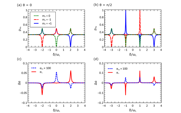
To model our system, we numerically solve Eq. S1 using the computational package for Python, QuTip [S1]. To begin with, we test the concept of the MAOP by looking at the populations in the absence of thermal relaxation. Figs. S2 (a) and (b) show the populations corresponding to the MAOP configurations from Figs. S1(c) and (d), respectively. These simulations show that a resonant microwave field clears out the addressed sublevels, moving the atomic population to the uncoupled sublevels.
In order to simulate the optical transmission shown in Fig. 3 of the main text, we first need to examine how the optical absorption depends on the distribution of the atomic population between the ground-state sublevels. For a dilute vapor, the absorption is given by
| (S2) |
where is the atomic density, is the length of the optical path in the medium and is the frequency-dependent absorption cross-section. For a particular transition, the cross-section is given by
where is a parameter which is the same for all transitions within the D2 line, is the fraction of atoms undergoing this transition, and is the dipole matrix element corresponding to this transition. In a thermal ensemble, due to the Doppler effect, the value of is a product of the fraction of atoms in the velocity class resonant with the transition at frequency () and the probability of an atom from this velocity class to be in the state
where is the atomic mass, is the ensemble temperature, is the Boltzmann constant, is the speed of light, is the optical laser frequency, and is the optical transition frequency in the atomic reference frame. For the D2-line, the transition matrix element given in multiples of is
where is the relative transition strength for the transition from to .
As in the measurements from the main text, we consider the case for which the probe is tuned to the transition. Because of Doppler broadening, three velocity classes contribute to the absorption: the zero-velocity atoms are resonant to the transition itself, which we represent by the frequency , and non-zero velocity classes are resonant to the other two transitions allowed by selection rules: and . Because the Doppler shift for the microwave field is negligible, the MAOP equally affects the three velocity classes. However, due to different coefficients representing the different strengths of these three transitions, each velocity class contributes to the total absorption differently. To take into account the cumulative effect that the population distribution (in the three velocity classes) has on the total absorption, we introduce a coefficient , such that , with given by
where is the total probe intensity and and are intensities of the and polarization components, and
where is the frequency of the transition.
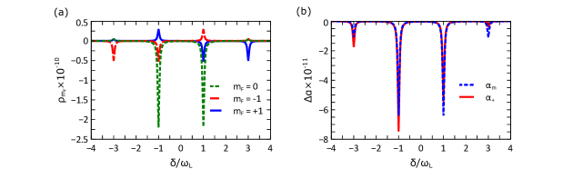
In our MAOP configuration, the atomic population depends on the microwave detuning , as does, therefore, the absorption, which we now represent as . Fig. S3 shows how changes due to MAOP with the microwave field detuned by from the clock transition. The simulation is done for the two cases of probe polarization corresponding to the experimental data from Fig. 3 in the main text: first, a -polarized probe, in which case , and second, a mixed polarization with
where half of the probe power corresponds to -polarization and the other half is split equally between and . As seen in [Fig. S3(a)], when there is no relaxation between the ground-state levels, MAOP should result in an antisymmetric absorption feature for a -polarized probe, and a symmetric feature for the probe with mixed polarization. In both cases, there is an increase in the absorption coefficient for some values of the microwave detuning, which is not what we observe experimentally, where the absorption decreases whenever the microwave field is on resonance. Upon adding thermal relaxation to the simulation results, we find the results seen in Fig. S3(b), which is similar to what we observe experimentally.
[S1] J. R. Johansson, P. D. Nation, and F. Nori, QuTiP 2: A Python framework for the dynamics of open quantum systems, Comput. Phys. Commun.184, 1234 (2013).
[S2] P. D. Nation, Steady-state solution methods for open quantum optical systems, arxiv.org , 1504.06768 (2015) .