Updating the SiD Detector concept
Abstract
The SiD Detector is one of two detector designs for the future International Linear Collider (ILC) that were validated in 2012 SiD features a compact, cost-constrained design for precision Higgs and other measurements, and sensitivity to a wide range of possible new phenomena. A robust silicon vertex and tracking system, combined with a five Tesla central solenoidal field, provides excellent momentum resolution. The highly granular calorimeter system is optimized for Particle Flow application to achieve very good jet energy resolution over a wide range of energies. With a potential construction date of the ILC moving closer, it is now the time to review the design and technology decision that have been made during the DBD phase and reconsider them in the light of the recent technological advances. For each area of SiD development R&D topics and opportunities for participation will be discussed.
I Introduction
The International Linear Collider (ILC) [1] is a proposed collider at the energy frontier. The ILC is a long linear accelerator using superconducting cavities with a initial baseline center-of-mass energy of 250 GeV. The ILC will provide polarized beams for both electrons (80%) and positrons (30%), which is a unique capability of linear colliders. The ILC project includes a clear upgrade path to center-of-mass energies of 1 TeV, or even slightly beyond. The ILC has a mature baseline design which has been summarized in the Technical Design Report (TDR), which was presented in 2012 [2, 3].
The ILC environment is unique and very different than at synchrotrons. The ILC accelerates a bunch train with 1300 bunches roughly apart roughly every , so collisions only happen during followed by a quiet time of . This allows to buffer the data on the front-ends, read out at the end of the bunch train and then to power down the front-ends (power-pulsing). This reduces the average power consumption by roughly a factor of 100.
SiD started as a detector concept for linear colliders almost twenty years ago [4, 5]. It was well documented in the ILC TDR Detailed Baseline Document (DBD) [6] in 2012. This note will first give a brief review on the current design and layout of SiD and then identify and highlight the improvements appropriate for a construction start in the late 2020s, and the new opportunities for R&D contributions. This note will not recapitulate the DBD in great details, and the reader should refer to the ILC TDR for a complete summary of the physics motivations [7], the ILC accelerator [3] and the conceptual detector designs[6]. For a review of the R&D activities in the Linear Collider Community, the Detector R&D Report [8] is an excellent summary.
II SiD Status for the DBD
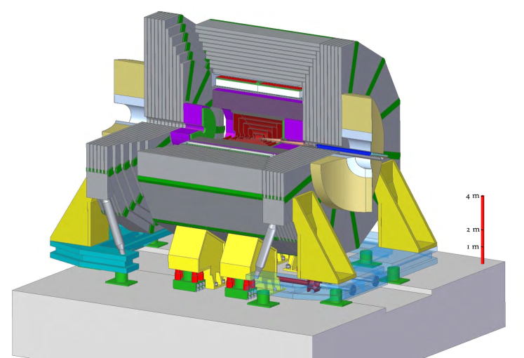
The SiD detector has been designed as a general-purpose experiment designed to perform precision measurements at the ILC. It satisfies the challenging detector requirements resulting from the full range of ILC physics processes and range of COM energies. SiD is based on the paradigm of particle flow, an algorithm by which the reconstruction of both charged and neutral particles is accomplished by an optimized combination of tracking and calorimetry. The net result is a significantly more precise jet energy measurement which results in a di-jet mass resolution good enough to distinguish between hadronically decaying s and s. The SiD detector (Fig. 1) is a compact detector based on a powerful silicon pixel vertex detector, silicon tracking, silicon-tungsten electromagnetic calorimetry, and highly segmented hadronic calorimetry. SiD also incorporates a high-field solenoid, iron flux return, a muon identification system, and forward calorimetry. The use of silicon sensors in the vertex, tracking, and calorimetry enables a unique integrated tracking system ideally suited to particle flow.
The choice of silicon detectors for tracking and vertexing ensures that SiD is robust with respect to beam backgrounds or beam loss, provides superior charged particle momentum resolution, and eliminates out-of-time tracks and backgrounds. The main tracking detector and calorimeters can time-stamp each individual bunch crossing, so beam-related backgrounds and low-background events originating from processes will be reduced to the minimum possible levels. The SiD calorimetry is optimized for excellent jet energy measurement using the particle flow technique. The complete tracking and calorimeter systems are contained within a superconducting solenoid, which has a field strength, enabling the overall compact design. The coil is located within a layered iron structure that returns the magnetic flux and is instrumented to allow the identification of muons. All aspects of SiD are the result of intensive and leading-edge research aimed at achieving performance at unprecedented levels. At the same time, the design represents a balance between cost and physics performance. The key parameters of the SiD design are listed in Table 1.

| SiD Barrel | Technology | In rad | Out rad | z extent |
| Vtx detector | Silicon pixels | 1.4 | 6.0 | |
| Tracker | Silicon strips | 21.7 | 122.1 | |
| ECAL | Silicon pixels-W | 126.5 | 140.9 | |
| HCAL | RPC-steel | 141.7 | 249.3 | |
| Solenoid | 5 Tesla SC | 259.1 | 339.2 | |
| Flux return | Scint-steel | 340.2 | 604.2 | |
| SiD Endcap | Technology | In z | Out z | Out rad |
| Vtx detector | Silicon pixels | 7.3 | 83.4 | 16.6 |
| Tracker | Silicon strips | 77.0 | 164.3 | 125.5 |
| ECAL | Silicon pixel-W | 165.7 | 180.0 | 125.0 |
| HCAL | RPC-steel | 180.5 | 302.8 | 140.2 |
| Flux return | Scint/steel | 303.3 | 567.3 | 604.2 |
| LumiCal | Silicon-W | 155.7 | 170.0 | 20.0 |
| BeamCal | Semicond-W | 277.5 | 300.7 | 13.5 |
III Changes to the Baseline post-DBD
With the completion of the DBD and the intention from the Japanese HEP community to host the ILC in Japan, two major design changes were made to the baseline designs, that was presented in the DBD, the switch from a purely digital hadron calorimeter (DHCAL) with RPCs as active medium [9, 10, 11, 12] to a scintillator-based solution with analog read-out (AHCAL)and the change of the iron yoke from a octagon to a dodecagon. The first choice was driven by the huge progress in the SiPM technology in terms of noise and stability, while at the same time the limitations of a large-scale RPC system with several million individual channels in terms of uniformity, calibration and long-term stability became more clear. As there were neither clear cost or performance benefits of the DHCAL at the time, this led to a switch to an AHCAL solution. The mechanical structure of the HCAL was left unchanged.
From a systems point of view, the elimination of both a HV system and an elaborated gas system had of course significant implications, as no other other sub-detector of SiD required such systems.
The second choice was mainly driven by site-specific studies for the potential Kitakami site. The SiD iron yoke is assembled by stacking of eleven individual iron plates into wedges. By switching the iron-yoke geometry from an octagon to a dodecagon, the weight of the individual plates could be kept below , allowing easier transport by truck on Japanese highways. At the same time the overall yoke design changed from a vertical interface between the barrel and endcap to a thirty degree interface.
IV Updating the SiD detector design
The last time the SiD detector design received a major overhaul was in the preparation of the DBD. With almost a decade past, technology choices, in particular, for the individual subsystems need to be reviewed. In the follow section, potential updates are outlined showcasing also the areas where dedicated R&D is needed and new contribution would be extremely welcome. Also with the advances in technology driven e.g. by the HL-LHC in terms of silicon sensor and ASIC development, novel timing detectors and improved services for power distribution and data transmission, it would be very interesting to explore how these could be incorporated into an updated SiD detector concept.
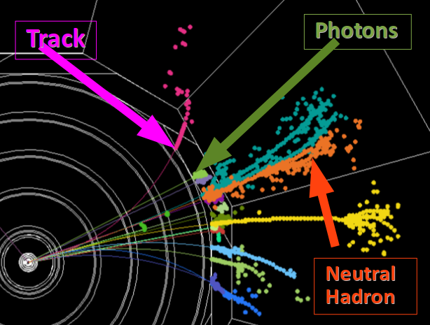
The use of Particle Flow Algorithms (PFA) for reconstruction puts significant constraints on the detector design. PFA detectors meed to have both the tracker and the calorimeter inside the solenoid for the best possible performance. in a typical jet, about 60% of the energy are due to charged particles, 30 % to to photons and 10 % due to neutral hadrons. PFA matches tracks with showers and therefore tries to measure the energy of the charged particles by using the most more precise momentum information from the tracker instead of the calorimeter measurement. Only the neutral energy measurements are determined by the calorimeters. Hence a key ingredient of any PFA detector is a combination of large tracker radius and a strong field to separate the clusters from charged and neutral particles. Secondly a very high granularity helps to separate the individual clusters and also is important to minimize the confusion, i.e. assigning individual calorimeter hits to the wrong cluster. A schematic view of a PFA reconstruction is shown in Figure 3.
The most commonly used PFA algorithm is PandoraPFA [13, 14], which has also been used extensively by SiD.
IV.1 Overall detector geometry
The overall detector geometry has been quite stable, but there have been a few areas of discussion over the last year, which need to be revisited on the road toward a TDR for SiD. Particularly the tracker geometry and the calorimeter thickness have a huge impact on both physics performance and cost. In the following a few points to be revisited and optimized are described in more detail.
IV.1.1 Tracker radius and aspect ratio
The outer radius of the tracker was fixed at , mainly driven by the need to fit both tracker and calorimeter inside the solenoid and the maximum radius of a solenoid with a field. Having a larger radius would help in the shower separation, which is beneficial for the PFA reconstruction. However, the current layout is already quite close to the maximum coil radius, so the impact of a modest increase of the radius needs to be studied. It was already concluded for the DBD, that a going significantly below radius, severely impacts the PFA performance [15]. For the DBD the tracker length was fixed to , as the tracker mechanica l support structure at the time would not allow a significant extension in length. Simulation studies have shown [15], that moving the transition between barrel and end-cap further out in could be beneficial for the overall performance of SiD.
IV.1.2 Thickness of the calorimeter system
The SiD calorimeter thickness (20+10 layers in the ECAL, 40 layers in the HCAL) was optimized to provide an excellent jet resolution from 91 GeV to 1 TeV. However the number of layers and total thickness of the system could be re-optimized, as the calorimeter system is a major cost driver. Studies for the ECAL as the major cost-driver have already shown, that for pure electromagnetic energy performance a thinner calorimeter would be sufficient [16].
IV.2 Monolithic Active Pixel Sensors
The SiD silicon baseline as described in the DBD based on two large area high-resistivity silicon diode arrays for both the main tracker and the ECAL that are read out with the bump bonded KPiX. The possibility of stitching reticules together with deep implants [17] and depletion of the epitaxial layer make Monolithic Active Pixel sensors (MAPS) is extremely attractive. SiD has currently focused its efforts on the Tower-Jazz process. The fundamental specifications are sensors of at least with pixels of . The same MAPS sensor could be used for the tracker and the ECAL. The sensor is readout by digital electronics on a ”balcony” high on one edge of the sensor. Each pixel should have at least simple discriminator (one bit) and needs to records the time for bunch identification. Distribution of power over such a large area is challenging. The working assumption is that flat cables will both handle control and data, as well as power distribution to the reticules.
IV.3 Vertex Detector
Since the DBD, SiD uses a vertex detector design with five individual layers in the barrel and four disks in the endcaps. Taking advantage of the large field, the inner radius of the Vertex Detector is merely away from the interaction point. This layout has been shown to give an excellent performance, however a further refinement of the layout is needed. The resolution requirements for the SiD Vertex Detector have remained unchanged since the DBD, a point resolution of better than , which mandates either pixels with a pure binary readout with a pixel pitch of , or a analog readout with a pixel pitch of 15-. While there have been many promising developments already [18, 19, 20, 21], a MAPS which is meeting all the SiD requirements is not yet available. The ongoing developments on the Tower-Jazz process are currently the most promising ones and the ALICE ITS3 upgrade will be the first major user of this technology. Given the currently foreseen assembly scheme, the Vertex Detector would be installed last and technology decisions can be taken much later than for other subsystems, taking full advantage of the latest developments in CMOS technology.
The beam background levels at the several proposed ILC operating energies are quite different [22], so the Vertex Detector is foreseen to be upgradable in a shutdown, which also opens the possibility to design an optimal Vertex Detector for each center-of-mass energy.
The impact of the layout and resolution as well as its material budget of the Vertex Detector on the flavor tagging performance need to be revisited. These studies will then also guide the design of a dedicated MAPS for the Vertex Detector.
IV.4 Tracker
The Tracker design described in the DBD is based on high-resistivity Silicon-strip sensors with a size of 10 and a strip-pitch of readout by a System on Chip (SOC) KPiX [23], bump bonded to the Silicon sensor. The sensor using a second metal layer to connect the individual strips to KPiX, and no hybrid is required. A fully functional prototype has recently been assembled tested [24] and achieved the desired resolution of . The overall tracker layout uses five nested cylinders in the barrel region and four disks following a conical surface with an angle of 5 degrees with respect to the normal to the beamline in each of the endcaps. In the endcaps, the disks use two sensors mounted back to back to allow a small-angle stereo configuration.
A MAPS-based tracker for SiD would be based on a similar size of the sensor, as described above. The sensors would be aligned with the 25 micron pixel dimension in the bend direction, and would have a resolution of 25/root(12) as charge sharing is not assumed. For the endcaps, such a sensor would eliminate the need for two sensors in a small-angle-stereo configuration, reducing both the material budget and cost.
IV.5 Common Tracking aspects
For SiD, the vertex detector and main tracker have always been treated as an integrated system. For the overall system the question remains if the current configuration could be improved and while the tracking resilience against backgrounds has been extensively tested, a detailed study of the robustness of the tracker towards failures of individual channels or complete sensors would be further input to the overall layout. Alignment of the tracking system will remain a challenge, as the level of e.g. Z events will be too small for beam-based alignment. Integrated scanning interferometers are expected to have adequate precision.
With the advent of fast timing and 4D-tracking, the impact on the performance of the SiD tracking system needs to be demonstrated.
Future studies for the tracking system include
-
•
Optimal Pixel size for the Vertex Detector and the tracker
-
•
Mechanical support structures, cooling and stability
-
•
Alignment studies
IV.6 Electromagnetic Calorimeter
The ECAL is a sampling calorimeter using W as a radiator with gaps for the Silicon sensors. The current design uses high resistivity sensors cut into hexagons that are as large as practical from a six inch wafer. Similarly to the Tracker, a KPiX ASIC is bump-bonded to each sensor. This concept has been successfully demonstrated in several beam tests [25] Given the huge technical progress made for MAPS, a study has started to consider large- area MAPS for the ECAL, eliminating the need for the delicate and expensive bump-bonding, while significantly improving the shower separation within the calorimeter.
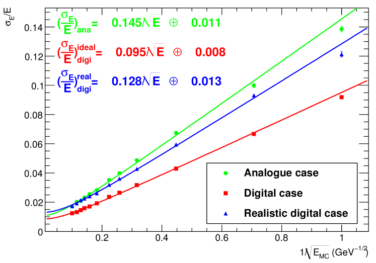
As discussed before, a pixel area of ( or ) is considered to be a sensible choice, and excellent performance with a purely digital ECAL based on this fine granularity is expected, but the use of some analog information will be investigated. Previous studies [26, 27, 28] have even indicated potential energy resolution advantages for a digital ECAL solution (see Figure 4).
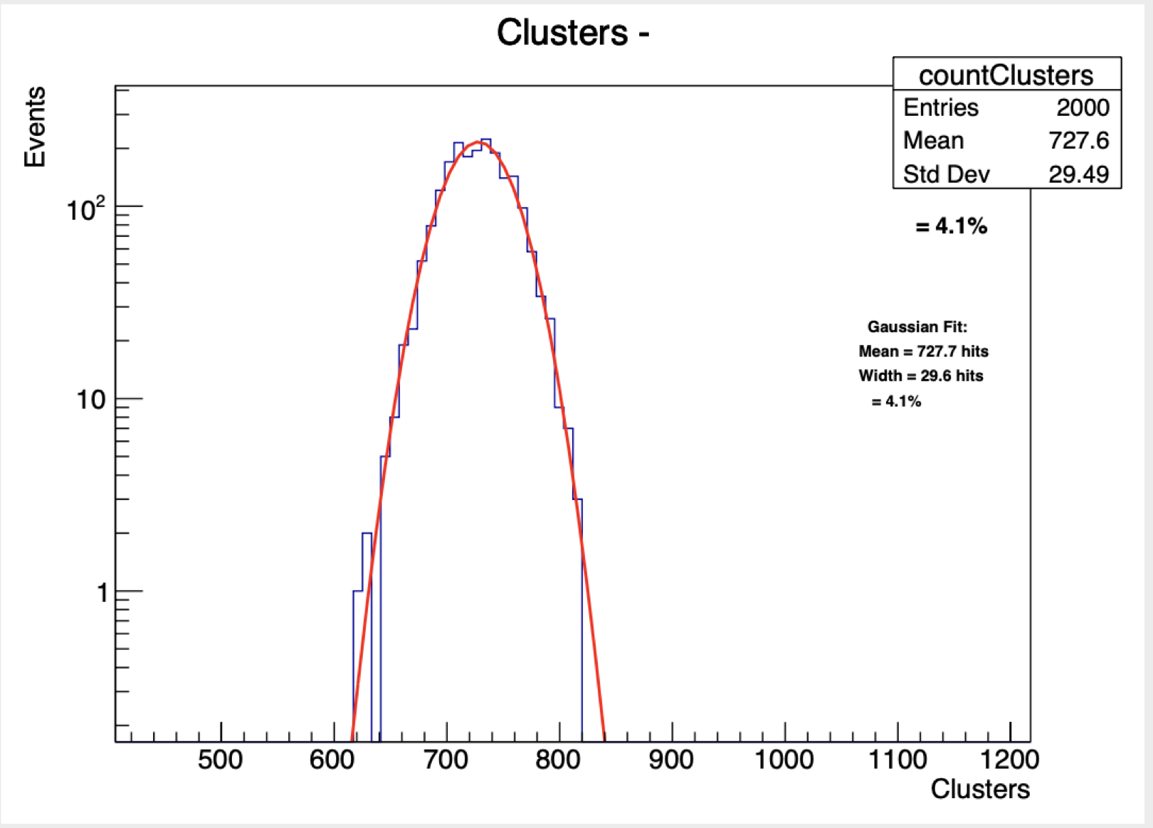
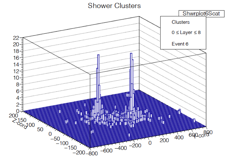
New simulation studies, based on this finer, digital configuration, have confirmed the previous studies referred to in Figure 4 and demonstrated additional details on the performance [29]. These studies indicate the electromagnetic energy resolution based on counting clusters of hits in the MAPS detectors should provide better performance than the SiD original design based on analog pixels. This is shown in Figure 5.
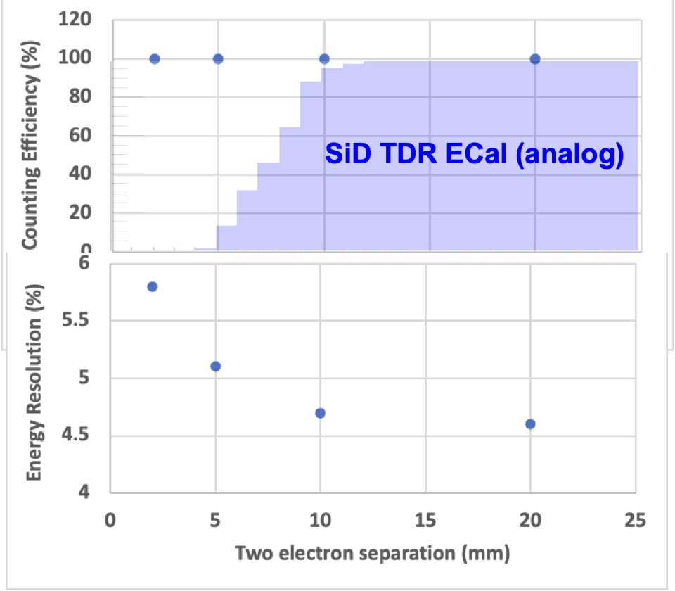
Furthermore, two shower separation is excellent, as shown in Figure 6. The fine granularity of pixels provides excellent separation. The performance for two showers versus their separation is summarized by Figure 7. The fine granularity allows for identification of two showers down to the millimeter scale of separation, and the energy resolution of each of the showers does not degrade significantly for the millimeter scale of shower separation.
Future studies include:
-
•
Optimal Pixel size for a MAPS-based ECAL
-
•
Choice between an analog or a digital ECAL
-
•
Optimization of the overall ECAL design
-
•
Optimization of the design for manufacturabilty, possibly with robots.
IV.7 Hadronic calorimeter
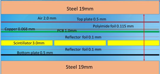
The current baseline design for the HCAL has active layers of small () scintillator tiles read out by silicon photomultipliers (SiPM), between steel absorber layers. There are 40 layers in the alternating active/absorber structure. There has been considerable development of this technology by the CALICE collaboration [30]. The SiD simulation includes a detailed description of the CALICE active layer design (Fig. 8).
To verify the performance of the SiD HCAL simulation, the single pion energy resolution has been compared with the results from the large-scale CALICE prototype. The comparison is shown in (Fig. 9) and shows good agreement between the simulation and the CALICE test beam results [31].

Previous simulation results have also shown that jet energy resolution in the 3-4% range can be achieved. However, as yet, the effects of variations and uncertainties arising from calorimeter design such as the number of layers, ratio of active to absorber layer thicknesses, calibrations within and between layers, transition regions between electromagnetic and hadronic systems and barrel and endcaps, and those deriving from e.g. confusion in the particle flow algorithm, have yet to be considered in terms of their influence on precision physics results. There is therefore a need for detailed studies of these effects and their potential for improving the HCAL design. Extensions to and optimization of the design should also address the following:
-
•
inclusion of timing layers to assist the particle flow algorithm in separating the delayed shower components from slow neutrons from the prompt components.
-
•
potential cost saving by making some of the outer layers thicker if there is no significant degradation in energy resolution.
-
•
optimization of the boundary region between the ECAL and the HCAL and optimization of the first layers of the HCAL to best assist with the measurement of electromagnetic shower leakage into the HCAL.
-
•
reconsideration of the effects of projective cracks between modules. There is some indication from earlier studies that projective cracks have no negative effect on energy resolution, but this needs further verification.
-
•
exploration of alternative layouts for HCAL sectors in the end-caps.
-
•
optimization of the boundary between the HCAL barrel and end-caps.
More to come here…
IV.8 Superconducting Coil
The SiD superconducting solenoid is based on the CMS solenoid design philosophy and construction techniques, using a slightly modified CMS conductor as its baseline design. Superconducting strand count in the coextruded Rutherford cable was increased from 32 to 40 to accommodate the higher central field.
Many iron flux return configurations have been simulated in two dimensions so as to reduce the fringe field. An Opera 3D calculation with the Detector Integrated Dipole (DID) coil has been completed. Calculations of magnetic field with a 3D ANSYS program are in progress. These will have the capability to calculate forces and stress on the DID as well as run transient cases to check the viability of using the DID as a quench propagator for the solenoid. Field and force calculations with an iron endcap HCAL were studied. The field homogeneity improvement was found to be insufficient to pursue this option.
Conceptual DID construction and assembly methods have been studied. The solenoid electrical power system,including a water-cooled dump resistor and grounding, was established. Significant work has been expended on examining different conductor stabiliser options and conductor fabrication methods. This work is pursued as a cost- and time-saving effort for solenoid construction.
Preliminary work has begun on the possibility of replacing the CMS conductor with Cable in Conduit Conductors (CICC). These cables are conduits of stainless steel with Ni-Ti conductor (for our relatively low fields) inside. The cable is cooled by flowing either superfluid or supercritical He. The advantages include elimination of a separate He vessel, smaller conductor cross section because of the tensile strength advantages of stainless over Aluminum, and easier construction. The interesting possibility is that the solenoid package thickness could be substantially reduced, leading to large cost reductions.
IV.9 Muon Detectors
The flux-return yoke is instrumented with position sensitive detectors to serve as both a muon filter and a tail catcher. The total area to be instrumented is very significant – several thousand square meters. Technologies that lend themselves to low-cost large-area detectors are therefore under investigation. Particles arriving at the muon system have seen large amounts of material in the calorimeters and encounter significant multiple scattering inside the iron. Spatial resolution of a few centimeters is therefore sufficient. Occupancies are low, so strip detectors are possible. The SiD baseline design uses scintillator technology. The scintillator technology uses extruded scintillator readout with wavelength shifting fibers and SiPMs, and has been successfully demonstrated [32] in terms of position and time resolution. Simulation studies have indicated that nine or more layers of sensitive detectors yield adequate energy measurements and good muon detection efficiency and purity. The flux-return yoke itself has been optimized with respect to the uniformity of the central solenoidal field, the external fringe field, and ease of the iron assembly. This was achieved by separating the barrel and end sections of the yoke along a 30 degree line.
Further development of the muon system will include:
-
•
Optimization of number of instrumented layers, barrel and end-caps.
-
•
Optimization of strip lengths, mainly for barrel system.
-
•
Design for muon endcaps - twelve-fold geometry.
-
•
Occupancies at inner radius of muon end-caps versus strip widths.
-
•
Role of muon system as tail-catcher for HCAL. Consideration and implications of CALICE ECAL + HCAL + Tail-catcher test beam results.
-
•
Potential for use of muon system in search for long-lived particles; timing and pointing capabilities.
V Forward systems
Two special calorimeters are foreseen in the very forward region: LumiCal for a precise luminosity measurement, and BeamCal for the fast estimation of the collision parameters and tagging of forward-scattered beam particles. LumiCal and BeamCal are both compact cylindrical electromagnetic calorimeters centered on the outgoing beam, making use of semiconductor-tungsten technology. BeamCal is placed just in front of the final focus quadrupole and LumiCal is aligned with the electromagnetic calorimeter endcap.
LumiCal makes use of conventional silicon diode sensor readout. It is a precision device with challenging requirements on the mechanics and position control, and must achieve a small Moliere radius to reach its precision targets. Substantial work has been done to thin the silicon sensor readout planes within the silicon-tungsten assembly. Dedicated electronics with an appropriately large dynamic range is under development.
BeamCal is exposed to a large flux of low-energy electron-positron pairs originating from beamstrahlung. These depositions, useful for a bunch-by-bunch luminosity estimate and the determination of beam parameters, require radiation hard sensors. The BeamCal has to cope with 100% occupancies, requiring dedicated front-end electronics. A challenge for BeamCal is to identify sensors that will tolerate over one MGy of ionizing radiation per year. Sensor technologies under consideration include polycrystalline chemical vapor deposition (CVD) diamond (too expensive to be used for the full coverage), GaAs, SiC, Sapphire, and conventional silicon diode sensors. The radiation tolerance of all of these sensor technologies has been studied in a high-intensity electron beams.
Tasks remaining for the forward calorimeters, with participation in the FCAL R&D Collaboration, include:
-
•
LumiCal: complete development of large dynamic range readout electronics.
-
•
LumiCal: develop and demonstrate the ability to position and maintain the position of the calorimeter, particularly at the inner radius, in view of the steep dependence of the rate of Bhabha events on polar angle.
-
•
BeamCal: continue the search for and testing of suitable sensor technology(s) capable of sustained performance in the very high radiation environment.
-
•
BeamCal: continue the study of recognizing single electron shower patterns for tagging for physics studies in the face of high radiation background.
VI Electronics & DAQ
The Electronics and DAQ needs are strongly tied to the ILC environment, with short bunch trains () followed by a long quiet time (), enabling front-end buffering and read-out during the quiet time and with power-pulsing the front-ends to reduce the overall power consumption. At the same time the physics event rate is a lot smaller than at e.g. the LHC and the main occupancy drivers are the beam backgrounds and the detector noise.
VI.1 Front-end electronics
With the incorporation of more and more MAPS-based subdetectors, the front-end ASICs become less and less widespread, and most likely the HCAL will be the first detector using classical front-end for reading out the SiPMs. At the same time, the role of data concentration will only increase, bundling the data streams from several MAPS units into high-speed data links and moving them off-detector. More development is needed for DC-DC converters that are in the magnetic field and deal elegantly with the pulsed front end load.
VI.2 DAQ
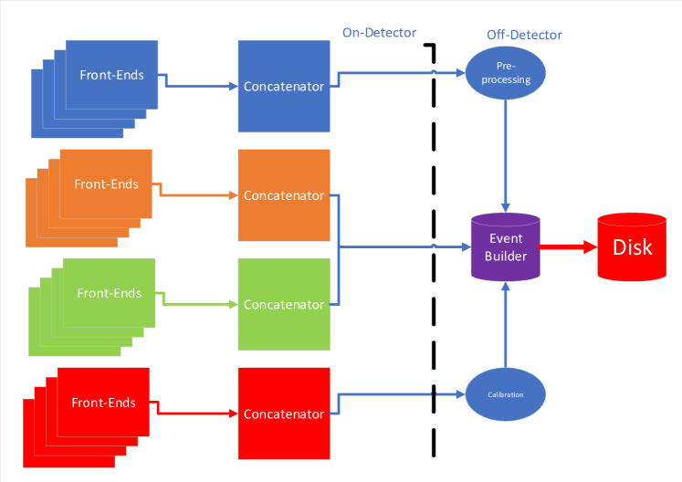
The data flow in any ILC detector is quite different compared to an LHC detector due the complete absence of triggering and the buffering on the front-end during the train. As described above, at the end of a bunch train, the data of all front-ends of a sub-detector is moved to the sub-detector data concentrators and from there, the data is sent off-detector using high-speed links. Depending on the sub-detectors, there are intermediate stages like calibration or pre-proproessing, before the complete events are being build by the event builder and then stored directly on disk. A event selection of interesting evenets will be done completely offline by the the physics analysis. A sketch of the data flow is shown in Fig. 10.
The DBD described a DAQ architecture based on ATCA, which was quite adequate for the relatively simple problem compared to the LHC detectors. Given the delay, the platform choice will be reviewed.
VII Machine Detector Interface
The Machine-Detector Interface (MDI) is a key part of any linear collider detector and essential for its performance. For the ILC it involves not only the machine optics like Final-Focus magnets but more generally any interface between the detector, the machine and the interaction region hall infrastructure Many of these activities are covered by both experts from the accelerator and detector community.
VII.1 Devices within of the beamline
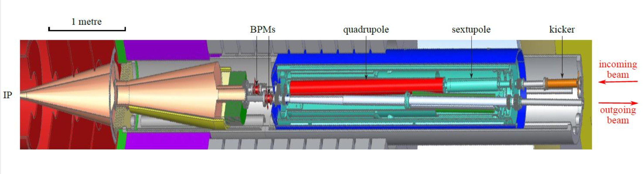
While engineering of the R25 region of the detector has begun, much work remains. See for example Figure 11. Devices within this region include:
-
•
Beam pipe
-
•
Luminosity Monitor
-
•
A possible forward Hadron calorimiter
-
•
Tungsten and polycarbonate masks
-
•
BeamCal
-
•
Feedback BPMs on incoming and outgoing beamlines after Beamcal and before QD0
-
•
The carbon fiber support tube that hold everything from the Beamcal to QD0
-
•
The piezo (or other) adjustment system, resident in the return yoke, that can align the support tube, allow the SiD Endcap Door to open and functions in the magnetic environment of the powered detector.
-
•
The feedback kicker
-
•
The gas valve and vacuum pumping system required to support detector interchange in push pull
-
•
The Frequency Scanning Interferometer for tracking system alignment
-
•
Any support system required to hold the fragile beampipe between the two support tubes
-
•
Cable and Fiber pathways for power and signals
Most of the work done in this area was completed 2012 for the DBD. Since that time L* has changed, the magnet yoke has changed and the beam parameters have changed. Optimizing the design for the final configuration will require new efforts.
VII.2 Devices further removed from the IP
Many challenging engineering and physics issues often associated with MDI need additional work. A short list includes:
-
•
Extraction line polarimeter, energy spectrometer and gamma calorimter
-
•
Incoming line polarimeter and energy spectometer
-
•
PACMAN shielding to maintain self-shielding
-
•
Push-Pull engineering details
-
•
Anti-Detector Integrated Dipole evaluation, risk analysis and integration with detector solenoid
-
•
Radiation dose calculations for accident scenarios and Beamcal exposure to pairs
-
•
Routing of liquid helium lines while allowing door opening and push-pull
VII.3 Beam backgrounds
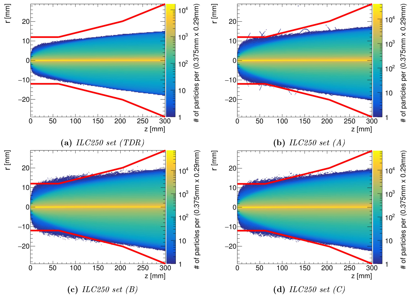
The main background at the ILC is due to beam-beam interaction. The choice of machine parameters has a big impact on the SiD design, it e.g. determines the beam-pipe radius (see Figure 12) and also has a big impact on the electronics design and in particular on the amount of front-end buffers necessary.
Future studies in this area include
-
•
Revisit the beam background studies with the latest beam parameters.
-
•
Radiation damage studies in Beamcal
-
•
Robustness of the final quad apertures to synchrotron radiation caused by less than optimal beam emittance or beam tails or beam jitter, especially as the machine starts up
VIII Software Developments
The simulation and reconstruction software stack for SiD is based on the DD4HEP [34] framework, which makes the simulation of various CALICE detectors available for evaluation in physics studies, and SiD uses the PandoraPFA [13, 14] and LCFIPlus [35, 36] packages for calorimeter reconstruction and flavor tagging, respectively. Looking forward, SiD is looking to keep pushing the envelope of modern software development.
VIII.1 Programming Languages for Framework and Analysis
C++ has been the lingua franca of particle physics-related software development over the past two decades or so. However, computer science classes in universities are increasingly teaching other languages 111For example, https://mitmath.github.io/18337/, compute accelerators like GP-GPUs are programmed in specialized languages like CUDA [38], and machine learning research is mostly done in Python and Julia [39], and the industry is looking to Go and Rust for better memory safety and support of multi-threading.
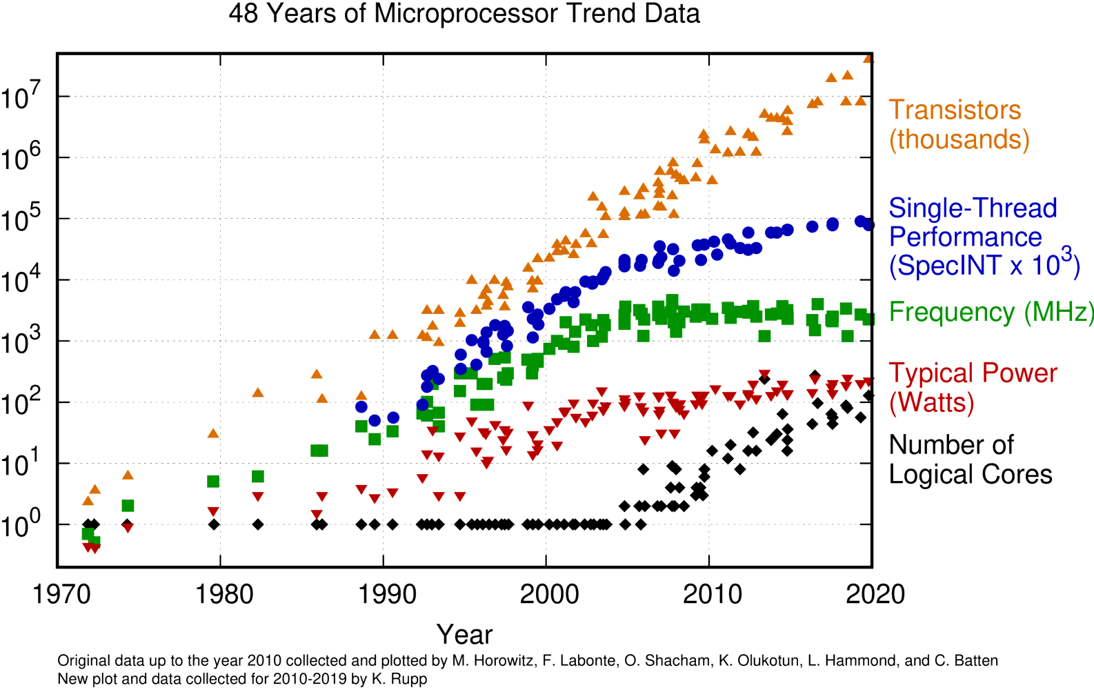
As recent analyses [40] have shown (see Figure 13),the single-thread performance and the closely linked clock-speed has been almost been leveling out since a decade, but the amount of cores per CPU has been growing exponentially. The overall transistor counts still follow an exponential growth line and with the the upcoming introduction of and processes nodes it is likely, that this trend will continue for the next few years. The gains seen for SpecINT to measure single-threaded performance are primarily due to compilers employing auto-vectorization and auto-parallelization [40]. Therefore, there is a clear need for a next-generation software framework to have the ability to utilize multi-core and heterogeneous hardware architectures.
In the upcoming phase of research and development we encourage the use of high-productivity languages for prototyping and design studies. Experience shows that many pieces of code from beam tests end up as parts of the experimental framework. The Julia programming language occupies an interesting point in the intersection of the high-productivity and high-performance language families [41]. This might obviate the translation of code from one language to another for performance reasons.
VIII.2 Common Event Data Model(EDM)
A common EDM has served the linear collider community very well and LCIO [42] has been very successful throughout the community. LCIO has bindings for many languages ranging from Fortran to Python and Julia, which has been another ingredient for its success. Both detector concepts for the ILC are strongly supporting maintaining a common EDM, as it increases the capability to quickly cross-check results and reduces the amount of manpower needed to support a multitude of EDMs. Updates to the EDM will support multi-threading and fast in-memory serialization to take advantage of the next-generation CPUs.
VIII.3 Simulation and Reconstruction Software developments
In the near term, SiD is going to develop an improved reconstruction for digital calorimetry and to study the use of timing information to improve the event reconstruction. Looking further ahead, the advent of machine learning techniques has brought many innovative solutions to jet tagging problems at the LHC. The level of detail available in an ILC event will lead to additional developments in this area. We expect reconstruction strategies using machine learning to have an improved performance over hand-crafted tools that take years to develop and often depend on only a few experts for maintenance and support. Reconstruction strategies using state-of-the-art machine learning methods allow data-driven methods for training and commissioning, and they facilitate the exchange of skills with other domains, which should ultimately make them easier to maintain and update.
In the area of simulation, Geant4 [43, 44, 45] is the engine of choice for SiD. However, for many aspects of the physics studies, this level of detail is not needed. Large savings in the CPU budget can be achieved by selecting a faster simulation procedure. Machine learning-based approaches will help to develop a faster simulation for large-scale production samples. Additionally, ML will help identify which level of detail is required for which application.
The relatively democratic distribution of processes in the electroweak sector in the ILC data sample might make it feasible to apply event-level matrix element methods to support the event interpretation. The ultimate goal of such an approach would be to predict the Feynman diagram based on the set of raw detector inputs. While this goal is quite likely out of reach for the start of the ILC, research in this sector can inform the detector design in the future and will improve the understanding of detector sensitivity to a variety of physics models.
IX Potential new subsystems
The most obvious addition to SiD is taking advantage of the recent improvements in fast-timing detectors.
IX.1 Timing layers
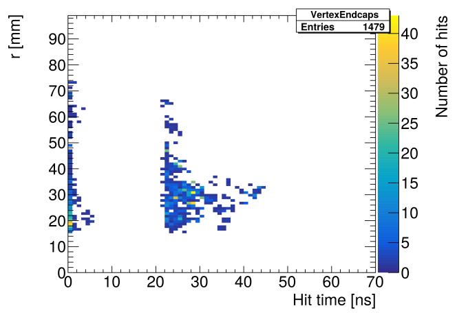
As noted above the introduction of timing layers into the HCAL could allow beneficial identification of slow shower components from prompt components. This would provide an extra dimension to resolving track-cluster associations, and following shower development from layer to layer (by associating equal-time items) in the PFA. Timing resolution at the nanosecond level should be sufficient for this application. In Figure 14 the timing distribution of the beam background hits is shown, cleary showing the collision and then with a clear separation the backgrounds hits from a backsplach from the forward instrumentation.
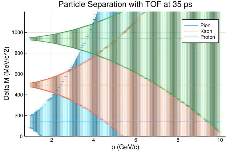
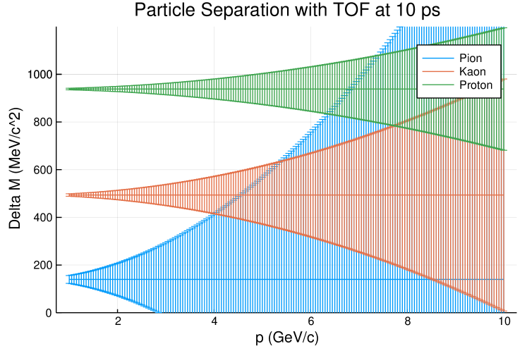
A timing layer as part of the tracking system or between tracker and ECAL could serve as a powerful Time-of-Flight system (TOF), where the physics reach needs to be further studied. It is already clear, that SiD would need to target a timing resolution in order of which is roughly a factor three to five better than the resolution target by the timing layers of ATLAS [46] and CMS [47]. A first performance study of a TOF layer located between the tracker and ECAL is shown in Figures 15 and Figure 16.
IX.2 Particle ID
Currently there is no dedicated Particle ID (PID) detector foreseen for SiD and a compelling physics case for a PID system besides timing-layer based solutions like a Time-of-Flight system would need to be demonstrated. Referring to Figures 15 and Figure 16 shows clearly that even with an excellent TOF system, a dedicated PID system is required, if there is a physics need for /K separation with particle momenta greater than a few GeV/c.
X Conclusion
SiD was originally conceived in the middle of the first decade of this century and technology has since then made major steps forward. With the realization of the ILC becoming now a real possibility, it is timely to revisit the technology choices and update them accordingly. The replacement of the silicon strips and pad systems in the tracker and ECAL with MAPS is an obvious decision given recent advances. For the HCAL the move to a SiPM-based readout has already been made, opening up also synergies with the SiD muon system.
References
- Behnke et al. [2013] T. Behnke, J. E. Brau, B. Foster, J. Fuster, M. Harrison, J. M. Paterson, M. Peskin, M. Stanitzki, N. Walker, and H. Yamamoto, The International Linear Collider Technical Design Report - Volume 1: Executive Summary, (2013), arXiv:1306.6327 [physics.acc-ph] .
- Adolphsen et al. [2013a] C. Adolphsen et al., The International Linear Collider Technical Design Report - Volume 3.I: Accelerator & in the Technical Design Phase, (2013a), arXiv:1306.6353 [physics.acc-ph] .
- Adolphsen et al. [2013b] C. Adolphsen, M. Barone, B. Barish, K. Buesser, P. Burrows, J. Carwardine, J. Clark, H. Mainaud Durand, G. Dugan, E. Elsen, et al., The International Linear Collider Technical Design Report - Volume 3.II: Accelerator Baseline Design, (2013b), arXiv:1306.6328 [physics.acc-ph] .
- Abe et al. [2001] T. Abe et al., Linear Collider Physics Resource Book for Snowmass 2001 - Part 4: Theoretical, Accelerator, and Experimental Options, (2001), arXiv:hep-ex/0106058 .
- Brau et al. [2004] J. Brau, M. Breidenbach, and Y. Fujii, The silicon detector (SiD) and linear collider detector \& in Asia and North America, in 4th ECFA / DESY Workshop on Physics and Detectors for a 90-GeV to 800-GeV Linear e+ e- Collider (2004) pp. 95–106.
- Abramowicz et al. [2013] H. Abramowicz et al., The International Linear Collider Technical Design Report - Volume 4: Detectors, (2013), arXiv:1306.6329 [physics.ins-det] .
- Baer et al. [2013] H. Baer, T. Barklow, K. Fujii, Y. Gao, A. Hoang, S. Kanemura, J. List, H. E. Logan, A. Nomerotski, M. Perelstein, et al., The International Linear Collider Technical Design Report - Volume 2: Physics, (2013), arXiv:1306.6352 [hep-ph] .
- Strube and Titov [2021] J. Strube and M. Titov, Detector Liaison Report v2021.2.2, Zenodo 10.5281/zenodo.4496000 (2021).
- Zhang et al. [2010] Q. Zhang, B. Bilki, J. Butler, E. May, G. Mavromanolakis, E. Norbeck, J. Repond, D. Underwood, and L. Xia, Environmental dependence of the performance of resistive plate chambers, Journal of Instrumentation 5 (02), P02007.
- Bilki et al. [2009a] B. Bilki, J. Butler, G. Mavromanolakis, E. May, E. Norbeck, J. Repond, D. Underwood, L. Xia, and Q. Zhang, Hadron showers in a digital hadron calorimeter, Journal of Instrumentation 4 (10), P10008.
- Bilki et al. [2009b] B. Bilki, J. Butler, E. May, G. Mavromanolakis, E. Norbeck, J. Repond, D. Underwood, L. Xia, and Q. Zhang, Measurement of the rate capability of resistive plate chambers, Journal of Instrumentation 4 (06), P06003.
- Bilki et al. [2009c] B. Bilki, J. Butler, E. May, G. Mavromanolakis, E. Norbeck, J. Repond, D. Underwood, L. Xia, and Q. Zhang, Measurement of positron showers with a digital hadron calorimeter, Journal of Instrumentation 4 (04), P04006.
- Thomson [2009] M. Thomson, Particle flow calorimetry and the pandorapfa algorithm, Nucl. Instrum. Meth. A611, 25 (2009).
- Marshall and Thomson [2015] J. S. Marshall and M. A. Thomson, The Pandora Software Development Kit for Pattern Recognition, Eur. Phys. J. C75, 439 (2015), arXiv:1506.05348 [physics.data-an] .
- Stanitzki [2009] M. Stanitzki, Detector Optimization for SiD using PFA, in International Linear Collider Workshop (LCWS08 and ILC08) (2009) arXiv:0902.3205 [physics.ins-det] .
- Braun et al. [2020] L. Braun, J. T. Barkeloo, J. E. Brau, and C. T. Potter, Energy Correction in Reduced SiD Electromagnetic Calorimeter, (2020), arXiv:2002.05871 [physics.ins-det] .
- Ballin et al. [2011] J. Ballin et al., Design and performance of a CMOS study sensor for a binary readout electromagnetic calorimeter, JINST 6, P05009, arXiv:1103.4265 [physics.ins-det] .
- Mager [2016] M. Mager (ALICE), ALPIDE, the Monolithic Active Pixel Sensor for the ALICE ITS upgrade, Nucl. Instrum. Meth. A 824, 434 (2016).
- Greiner et al. [2011] L. Greiner et al., A MAPS based vertex detector for the STAR experiment at RHIC, Nucl. Instrum. Meth. A 650, 68 (2011).
- Sinev et al. [2015] N. Sinev, J. Brau, D. Strom, C. Baltay, W. Emmet, and D. Rabinowitz, Chronopixel project status, Proceedings, 24th International Workshop on Vertex Detectors (Vertex 2015): Santa Fe, New Mexico, USA, June 1-5, 2015, PoS VERTEX2015, 038 (2015).
- Pernegger et al. [2017] H. Pernegger et al., First tests of a novel radiation hard CMOS sensor process for Depleted Monolithic Active Pixel Sensors, JINST 12 (06), P06008.
- Schütz [2018a] A. Schütz, Impact of the new ILC250 beam parameter set on the SiD vertex detector occupancy arising from e+e- pair background, in International Workshop on Future Linear Collider (2018) arXiv:1801.04156 [physics.ins-det] .
- Brau et al. [2012] J. Brau, M. Breidenbach, A. Dragone, G. Fields, R. Frey, D. Freytag, M. Freytag, C. Gallagher, G. Haller, R. Herbst, B. Holbrook, R. Lander, A. Moskaleva, C. Neher, T. Nelson, S. Schier, B. Schumm, D. Strom, M. Tripathi, and M. Woods, Kpix - a 1,024 channel readout asic for the ilc, in Nuclear Science Symposium and Medical Imaging Conference (NSS/MIC), 2012 IEEE (2012) pp. 1857–1860.
- Brau et al. [2020] J. Brau et al., Lycoris – a large-area, high resolution beam telescope, (2020), arXiv:2012.11495 [physics.ins-det] .
- Barkeloo et al. [2019] J. Barkeloo et al., A silicon-tungsten electromagnetic calorimeter with integrated electronics for the International Linear Collider, J. Phys. Conf. Ser. 1162, 012016 (2019).
- Ballin et al. [2009] J. Ballin, P. Dauncey, A.-M. Magnan, M. Noy, Y. Mikami, et al., A Digital ECAL based on MAPS, (2009), arXiv:0901.4457 [physics.ins-det] .
- Stanitzki [2011] M. Stanitzki (SPiDeR Collaboration), Advanced monolithic active pixel sensors for tracking, vertexing and calorimetry with full CMOS capability, Nucl.Instrum.Meth. A650, 178 (2011).
- Dauncey [2010] P. Dauncey (SPiDeR Collaboration), Performance of CMOS sensors for a digital electromagnetic calorimeter, PoS ICHEP2010, 502 (2010).
- Brau [2021] J. Brau, private communication, Tech. Rep. (2021).
- Sefkow et al. [2016] F. Sefkow, A. White, K. Kawagoe, R. Pöschl, and J. Repond, Experimental Tests of Particle Flow Calorimetry, Rev. Mod. Phys. 88, 015003 (2016), arXiv:1507.05893 [physics.ins-det] .
- Bilki et al. [2015] B. Bilki, J. Repond, L. Xia, and G. E. et.al., Pion and proton showers in the calice scintillator-steel analogue hadron calorimeter, Journal of Instrumentation 10 (04), P04014.
- Denisov et al. [2017] D. Denisov, V. Evdokimov, S. Lukić, and P. Ujić, Test beam studies of the light yield, time and coordinate resolutions of scintillator strips with WLS fibers and SiPM readout, Nucl. Instrum. Meth. A 848, 54 (2017), arXiv:1611.03211 [physics.ins-det] .
- Schütz [2018b] A. Schütz, Optimizing the design of the Final-Focus region for the International Linear Collider, Ph.D. thesis, KIT, Karlsruhe, Hamburg (2018b).
- Frank et al. [2014] M. Frank, F. Gaede, C. Grefe, and P. Mato, Dd4hep: A detector description toolkit for high energy physics experiments, Journal of Physics: Conference Series 513, 022010 (2014).
- Suehara and Tanabe [2016] T. Suehara and T. Tanabe, LCFIPlus: A Framework for Jet Analysis in Linear Collider Studies, Nucl. Instrum. Meth. A808, 109 (2016), arXiv:1506.08371 [physics.ins-det] .
- Bailey et al. [2009] D. Bailey et al. (LCFI), The LCFIVertex package: vertexing, flavour tagging and vertex charge reconstruction with an ILC vertex detector, Nucl. Instrum. Meth. A610, 573 (2009), arXiv:0908.3019 [physics.ins-det] .
- Note [1] For example, https://mitmath.github.io/18337/.
- Cook [2012] S. Cook, CUDA Programming: A Developer’s Guide to Parallel Computing with GPUs, 1st ed. (Morgan Kaufmann Publishers Inc., San Francisco, CA, USA, 2012).
- Bezanson et al. [2017] J. Bezanson, A. Edelman, S. Karpinski, and V. Shah, Julia: A fresh approach to numerical computing, SIAM Review 59, 65 (2017).
- Rupp [2019] K. Rupp, 48 years of microprocessor trend-data, https://github.com/karlrupp/microprocessor-trend-data (2019).
- Stanitzki and Strube [2020] M. Stanitzki and J. Strube, Performance of Julia for High Energy Physics Analyses, (2020), arXiv:2003.11952 [physics.comp-ph] .
- Gaede et al. [2003] F. Gaede, T. Behnke, N. Graf, and T. Johnson, LCIO: A Persistency framework for linear collider simulation studies, Proceedings, 13th International Conference on Computing in High-Enery and Nuclear Physics (CHEP 2003): La Jolla, California, March 24-28, 2003, eConf C0303241, TUKT001 (2003), arXiv:physics/0306114 [physics] .
- Agostinelli et al. [2003] S. Agostinelli, J. Allison, K. Amako, et al., Geant4—a simulation toolkit, Nuclear Instruments and Methods in Physics Research Section A: Accelerators, Spectrometers, Detectors and Associated Equipment 506, 250 (2003).
- Allison et al. [2006] J. Allison, K. Amako, J. Apostolakis, et al., Geant4 developments and applications, IEEE Transactions on Nuclear Science 53, 270 (2006).
- Allison et al. [2016] J. Allison, K. Amako, J. Apostolakis, et al., Recent developments in Geant4, Nuclear Instruments and Methods in Physics Research Section A: Accelerators, Spectrometers, Detectors and Associated Equipment 835, 186 (2016).
- CER [2020] Technical Design Report: A High-Granularity Timing Detector for the ATLAS Phase-II Upgrade, Tech. Rep. CERN-LHCC-2020-007. ATLAS-TDR-031 (CERN, Geneva, 2020).
- CER [2017] Technical Proposal for a MIP Timing Detector in the CMS Experiment Phase 2 Upgrade, Tech. Rep. CERN-LHCC-2017-027. LHCC-P-009 (CERN, Geneva, 2017).