XXXX-XXXX
1]Kamioka Observatory, Institute for Cosmic Ray Research, University of Tokyo, Hida, Gifu 506-1205, Japan 2]Kavli Institute for the Physics and Mathematics of the Universe (WPI), The University of Tokyo Institutes for Advanced Study, University of Tokyo, Kashiwa, Chiba 277-8583, Japan 3]Research Center for Neutrino Science, Tohoku University, Sendai 980-8578, Japan *]E-mail: mshibata@km.icrr.u-tokyo.ac.jp
Precise measurement of the scintillation decay constant of ZnWO4 crystal
Abstract
The scintillation decay time constant of a ZnWO4 crystal irradiated with -particles from 241Am was precisely investigated, and was found to depend on the incident direction of the -particles on the crystal. The longest decay time constant (s) was obtained on the surface perpendicular to the b-axis of the crystal (Surface B). On Surfaces A and C, the decay constants were and s, respectively. The scintillation yield of the ZnWO4 was also anisotropic and depended on the incident direction of the heavy particles. The maximum yield was achieved on surface B, suggesting a correlation between the light yield and scintillation decay time constant of ZnWO4 crystals.
H20, C40, C43
1 Introduction
The existence of dark matter has been suggested by many observations of the universe at various scales. Among the dark matter candidates are weakly interacting massive particles (WIMPs), which are expected to be observed by elastic scattering with nuclei on the Earth Drukier . Assuming that WIMPs in the galaxy follow the Maxwell distribution, the Earth is subjected to a WIMP wind caused by galactic rotation. Therefore, the most convincing signatures of WIMPs should appear in the directions of nuclear recoils Spergel , which can be monitored by detectors sensitive to these directions. Anisotropic scintillation crystals, in which the scintillation efficiency depends on the direction of heavily charged incident particles, have been investigated for this purpose Belli1992 ; Spooner ; Sekiya . With these crystals, the WIMPs’ signal can be obtained by comparing the visible energy spectra measured for different orientations related to the WIMP wind. The anisotropic scintillation response of ZnWO4 crystals was first reported in 2005 Danevich2005 ; Belli2011 ; Cappella2013 and has since been measured under irradiation with and neutron sources Juan2020 ; Ichimura2020 ; Belli2020 . The radiopurity of ZnWO4 is considered as an advantage in dark matter detectors Barabash2016 ; Belli2019 .
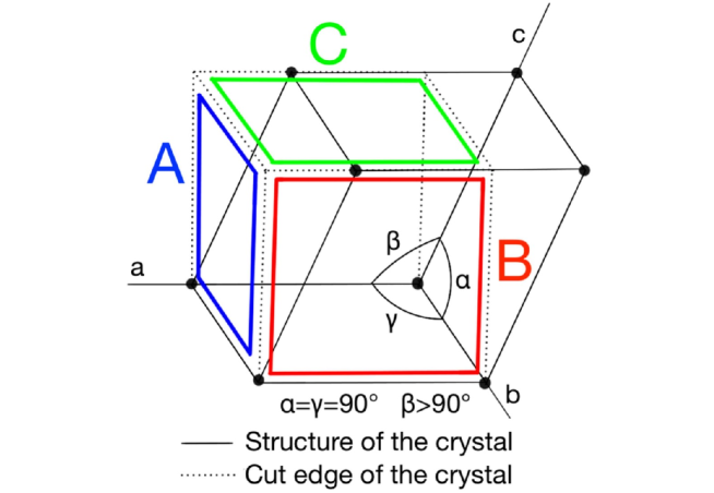
ZnWO4 is a colorless, transparent, monoclinic inorganic scintillation crystal. The basic properties of ZnWO4 are tabulated in Table 1 and the length and angle parameters of the unit cell of ZnWO4 are shown in Table 2.
| Molar mass | 313.22 |
|---|---|
| Density | 7.87 |
| Melting point | 1200 ∘C |
| Mohs hardness | 44.5 |
| Reflective index | 2.12.2 |
| [deg.] | [deg.] | [deg.] |
|---|---|---|
| 90.0000 | 90.6210 | 90.0000 |
| a[Å] | b[Å] | c[Å] |
| 4.96060 | 5.718201 | 4.92690 |
ZnWO4 scintillation crystals are also characterized by their long decay time. In the 1980’s, the decay time constant of ZnWO4 was reported as 20 s under -ray irradiation by Hol et al. Holl1988 and as 21.8 s under X-ray irradiation by Grabmaier et al. Grabmaier1984 . In the 2000’s, the decay time constant of ZnWO4 was refined into three components: 25 s, 7 s, and 0.7 s at 295 K under -ray irradiation from 137Cs Nagornaya2009 and s, s, and s at 295 K under -particle irradiation from 241Am Kraus2005 . However, the crystal orientations were not identified.
As the scintillation yields of ZnWO4 crystal under heavily charged particles depend on the incident direction, the scintillation decay time constant might similarly depend on the incident direction. To test this idea, we systematically measured the scintillation decay time of a ZnWO4 crystal in different orientations irradiated with -particles.
2 Experimental Setup
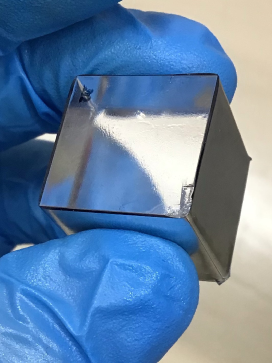
The decay times were evaluated on a ZnWO4 crystal with cubic dimensions (2 cm2 cm2 cm). The crystal was produced at the Laboratory of Crystal Growth, Nikolaev Institute of Inorganic Chemistry in Russia and was cut by Crystal Manufacturing Lab. Ltd. (Russia) Ichimura2020 . During cutting, the shape of the monoclinic unit cell was preserved as far as possible (see Fig. 1). The bottom surface was that of the unit cell and the surfaces were parallel to the unit cell. Surfaces A, B, and C were perpendicular to the a-, b-, and c-axes, respectively. The accuracy of the crystal cut was confirmed to be within 1∘ Juan2020 .
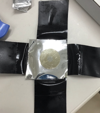
To investigate scintillation decay in the ZnWO4 crystal, the crystal was irradiated with a -ray source (708 kBq of ) and an -particle source (2.9 kBq of ). The side of the cubic crystal was wrapped with reflective sheets composed of 0.05 m-aluminized 50 m-thick polyethylene terephthalate film as shown in Fig. 2. For -particle irradiation, the 241Am source was placed in direct contact with the top of the crystal (surface A, B, or C) and was covered with the reflective sheet. The bottom of the crystal was attached to a 1”- PMT (Hamamatsu H6410) with optical grease (Adhesive Materials Group, V-788). The crystal was fixed with a mounter constructed from Styrofoam. The -ray irradiation experiment was configured similarly, but the top of the crystal was directly covered with the reflective sheet and the 137Cs source was placed 20 cm from the crystal to prevent signal pile-up.
The PMT was operated at a gain of and an applied voltage of 2200 V. Waveform signals from the anode were recorded with a digital storage oscilloscope at a sampling rate of 1GS/s (Tektronix TBS1064). The measurements were conducted in the laboratory under temperature control at 21∘C.
3 Results
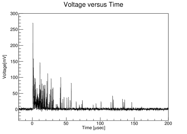
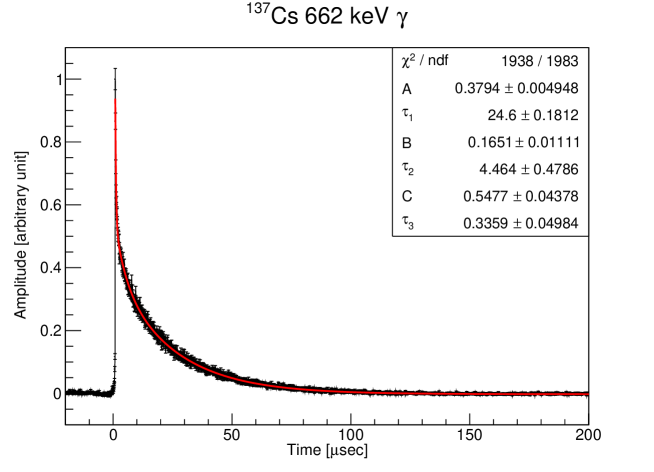
A typical recorded waveform of the ZnWO4 scintillator irradiated with -rays from 137Cs is shown in Fig. 3. The waveform shows the typical structure of a train of photoelectrons distributed over tens of s. Therefore, to determine the precise decay time constants, the waveforms were statistically averaged over many waveforms. To this end, more than 6000 waveforms were recorded in each measurement. The total area of each waveform was calculated by integrating the data over the range 0 to 200 s and an energy spectrum was obtained for each measurement. Next, 3000 waveforms of the 662 keV events from 137Cs and 3000 waveforms of the 5.4 MeV events from 241Am were selected and each waveform was normalized by its total area. The averaged waveforms were obtained by adding the 3000 normalized waveforms. Finally the waveform was normalized again by the peak amplitude.
The decay time constant was obtained by fitting the exponential functions of three components using the least-squares method. The fitting equation was given by
Figure 4 shows the obtained waveforms and the fitting results of -ray irradiation from 137Cs. The three components of the decay time were calculated as 24.6 0.2 s, 4.46 0.48 s and 0.34 0.05 s (see Table 3).
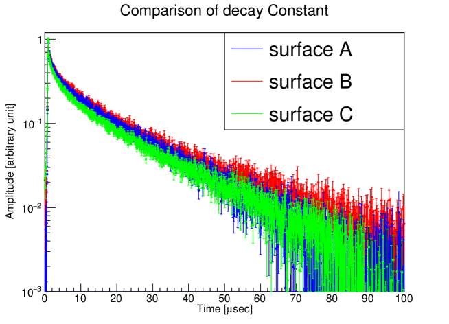
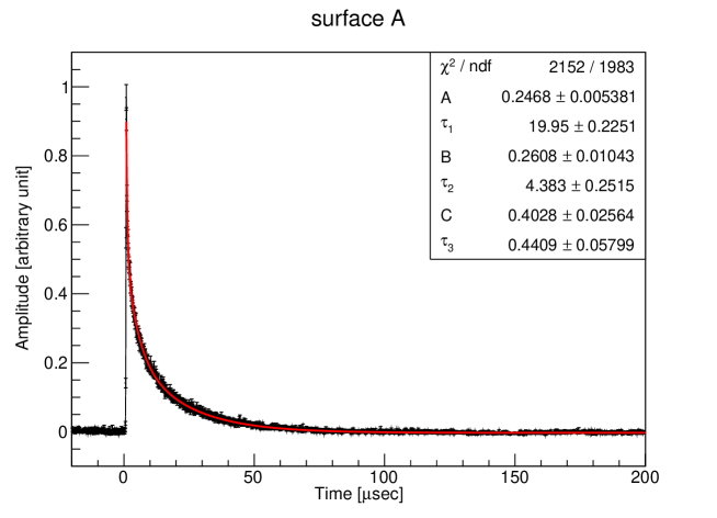
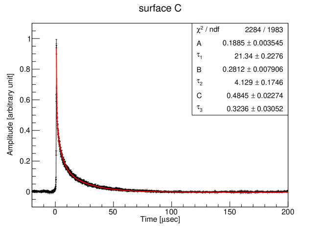
The waveforms of surfaces A, B, and C irradiated with -particles from 241Am are shown in Fig. 5, and their fitting results are shown in Figs. 6,7, and 8 respectively. The derived decay time constants are summarized in Table 3. The longest components of the decay time constants at surfaces A, B, and C under the -particle irradiation were 20.0 0.2 s, 24.3 0.6 s, and 21.3 0.2 s, respectively.
| source | decay constant[s] | / ndf | coefficient[] | ||||||
|---|---|---|---|---|---|---|---|---|---|
| 137Cs |
|
1938/1983 |
|
||||||
| 241Am A surface |
|
2152/1983 |
|
||||||
| 241Am B surface |
|
1998/1983 |
|
||||||
| 241Am C surface |
|
2284/1983 |
|
4 Conclusion
The anisotropic scintillation responses of a ZnWO4 crystal to heavy particles Juan2020 ; Ichimura2020 were investigated by irradiating each surface of the cubic crystal with -particles from 241Am and obtaining the scintillation decay time constants. The main components of the time constants depended on the incident surface. The longest time constant was s on surface B, where the light yield was also maximized. The other time constants were s on surface A and s on surface C. When 662 keV -rays were irradiated on the crystal surface, the longest time constant was s, close to that of surface B irradiated with -particles, and consistent with previously reported values Nagornaya2009 ; Kraus2005 . These measured time constants suggest that the anisotropy of the light yields originates from the scintillation decay process. Using scintillation waveform information of ZnWO4, in addition to the total light yields, may enhance the direction sensitivity to the WIMP wind.
Acknowledgment
This work was supported by JSPS KAKENHI grant numbers 15K13478 and 17H02884 and by Grant for Basic Science Research Projects from The Sumitomo Foundation.
References
-
(1)
A. K. Drukier, K. Freese and D. N. Spergel, Phys. Rev. D 33, 3495 (1986).
https://doi.org/10.1103/PhysRevD.33.3495 -
(2)
D. N. Spergel, Phys. Rev. D 37, 1353 (1988).
https://doi.org/10.1103/PhysRevD.37.1353 -
(3)
P. Belli, et al., Nuovo Cimento C 15 473 (1992).
https://doi.org/10.1007/BF02511747 - (4) N. J. C. Spooner, et al., International Workshop on Identification of Dark Matter World Scientific, Singapore 481 (1997).
-
(5)
H. Sekiya, M. Minowa, Y. Shimizu, Y. Inoue and W. Suganuma
, Phys. Lett. B 571 132 (2003).
https://doi.org/10.1016/j.physletb.2003.07.077 -
(6)
F. A. Danevich et al.,
Nucl. Instrum. Methods. Phys. Res. A, 544 553 (2005).
https://doi.org/10.1016/j.nima.2005.01.303 -
(7)
P. Belli et al.,
Nucl. Instrum. Methods. Phys. Res. A, 626-627 31 (2011).
https://doi.org/10.1016/j.nima.2010.10.027 -
(8)
F. Cappella, R. Bernabei, P. Belli, et al., Eur. Phys. J. C 73, 2276 (2013).
https://doi.org/10.1140/epjc/s10052-013-2276-2 -
(9)
A. S. Barabash et al.,
Nucl. Instrum. Methods. Phys. Res. A, 833 77 (2016).
https://doi.org/10.1016/j.nima.2016.07.025 -
(10)
P. Belli et al.,
Nucl. Instrum. Methods. Phys. Res. A, 935 89 (2019).
https://doi.org/10.1016/j.nima.2019.05.014 -
(11)
J. W. Pedersen, H, Sekiya, K, Ichimura, Prog. Theor. Exp. Phys. 023C01, 2 (2020).
https://doi.org/10.1093/ptep/ptz168 -
(12)
Koichi Ichimura et al., IEEE Trans. Nucl. Sci. 67, 894 (2020).
https://doi.org/10.1109/TNS.2020.2985027 -
(13)
P. Belli et al.,
Eur. Phys. J. A 56, 83 (2020).
https://doi.org/10.1140/epja/s10050-020-00094-z -
(14)
I. Holl, E. Lorenz, and G. Mageras IEEE Trans. Nucl. Sci. 35, 105 (1988).
https://doi.org/10.1109/23.12684 -
(15)
B. C. Grabmaier, IEEE Trans. Nucl. Sci. 31, 372 (1984).
https://doi.org/10.1109/TNS.1984.4333280 -
(16)
L. L. Nagornaya, B. V. Grinyov, A. M. Dubovik, et al., IEEE Trans. Nucl. Sci. 56, 994 (2009).
https://doi.org/10.1109/TNS.2009.2016342 -
(17)
H. Kraus, V. B. Mykhaylyk and D. Wahl, Nucl. Instrum. Methods. Phys. Res. A, 553 522 (2005).
https://doi.org/10.1016/j.nima.2005.07.011