Strong parametric coupling between two ultra-coherent membrane modes
Abstract
We demonstrate parametric coupling between two modes of a silicon nitride membrane. We achieve the coupling by applying an oscillating voltage to a sharp metal tip that approaches the membrane surface to within a few . When the voltage oscillation frequency is equal to the mode frequency difference, the modes exchange energy periodically and much faster than their free energy decay rate. This flexible method can potentially be useful for rapid state control and transfer between modes, and is an important step towards parametric spin sensing experiments with membrane resonators.
Optomechanical resonators made from silicon nitride are a key resource for future technologies [1, 2, 3, 4, 5, 6, 7, 8]. Owing to their very large quality factors, these devices are highly coherent and extremely sensitive to external forces [9]. They can interact with mechanical, electrical, optical and magnetic signals, and their mechanical mode shapes and resonance frequencies can be tailored to specific situations. Promising applications of such resonators include demonstrations of fundamental light-matter interactions [10, 11, 12], gravitational-wave detection [13], quantum-coherent signal conversion between the microwave and optical domains [14, 15], scanning force microscopy [9], and nanoscale magnetic resonance imaging [16, 17].
One crucial ingredient for harnessing optomechanical resonators for applications involves parametric coupling, also known as parametric frequency conversion, mode locking or three-wave mixing. This method for coupling non-degenerate modes, employed since a long time in electronics and nonlinear optics [18], can also be applied to nanomechanical resonators [19]. In parametric coupling, two modes with frequencies and are coupled through a pump tone at the frequency difference . Due to the pump tone, the modes experience each other’s oscillations as resonant forces, similar to coupled degenerate resonators. However, implementing efficient parametric coupling with ultra-coherent optomechanical devices is difficult – the very shielding from the environment that facilitates exceptionally high quality factors [5, 6] makes the implementation of a strong pump tone challenging. As a result, strong parametric coupling [20, 21], where the rate of energy exchange between two nondegenerate modes exceeds their individual decay rates, has so far not been demonstrated with ultra-high resonators.
In this work, we demonstrate strong parametric coupling between two shielded mechanical modes in a silicon nitride membrane. We circumvent the shielding issue with a sharp metallic tip that approaches the membrane to a few , enabling local and precise control of the electrical interaction force gradient. With this control, we demonstrate parametric coupling with a time required to transmit energy from one mode to the other and back, roughly 7 times faster than the mechanical decay time . Our method can be further improved by increasing the power delivered by the electrical pump tone, the electrical make-up of the membrane surface, and the quality factor of the mechanical modes, leading ultimately to quantum coherent state transfer between non-degenerate modes.
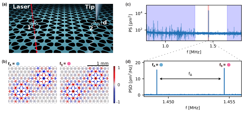
At the heart of our experiment is a silicon nitride membrane resonator whose displacement is detected with a power-balanced laser interferometer at , see Fig. 1(a). The time-dependent light intensity is transformed into an electrical signal and measured with a Zurich Instruments HF2LI lock-in amplifier. A sharp (rigid) metal tip can be scanned over the membrane surface with a three-axis stage [9]. The -thick membrane features a hole pattern that implements a phononic crystal [5]. Two ‘lotus’ defect [22] islands in the pattern with a separation of roughly and with quality factors act as isolated resonators 1 and 2. The symmetric (S) and antisymmetric (A) normal modes of these resonators, shown in Fig. 1(b), extend over both defect sites.[23] In the spectra in Fig. 1(c) and (d), the normal modes appear as narrow lines at frequencies inside the bandgap created by the phononic crystal.
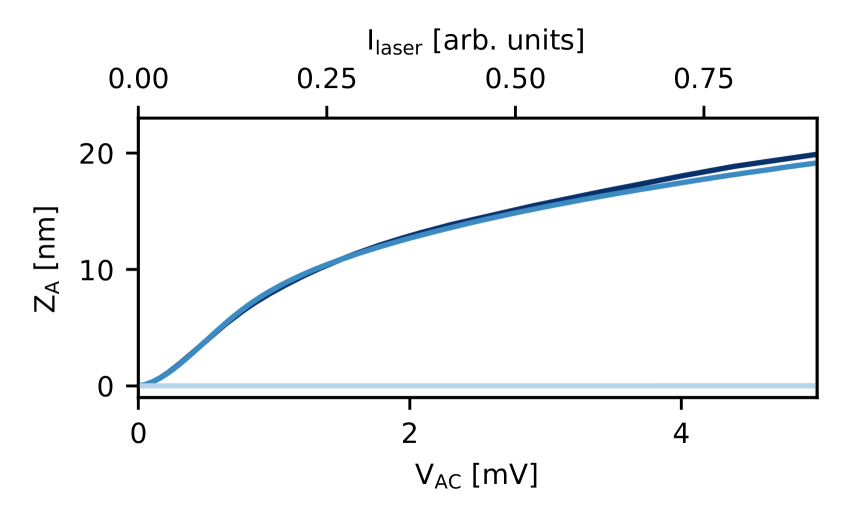
We can apply resonant driving forces to the two modes and measure their oscillatory response, see Fig. 2. First, we drive mode A with the photon pressure of a laser whose intensity is modulated at [9], generating a force . Second, we drive the same mode by modulating the voltage applied to the scanning tip as [9]. The response for exhibits the same nonlinear saturation at large amplitudes as obtained with the photon drive. There are three possibilities how an electrical force can arise: (i) for a conducting sample, a Coulomb force is generated between the charged tip and mirror charges on the membrane surface. Since our membrane is made from a dielectric, we think this to be an unlikely option. (ii) The dielectric membrane material can become polarized in response to the applied voltage [24]. For both (i) and (ii), we expect and that the force appears at instead of . However, our measurements indicate and the vibrational response when driving at , shown in Fig. 2 for comparison, is negligible. (iii) We finally propose that the force is caused by the interaction of the tip with ‘voltage patches’ on the membrane surface [25, 26, 27, 28, 29, 30, 31]. A similar interaction was recently observed with a different nanomechanical system [32]. This model can qualitatively explain all phenomena in Fig. 2. Additional data in the Supplemental material [33] support this interpretation. A quantitative analysis will be the subject of future work.
Our system can be modeled with a set of coupled equations of the form
| (1a) | |||
| (1b) | |||
Here is the displacement (with dots signifying time derivatives), the angular resonance frequency, the dissipation coefficient of mode with quality factor , the effective mass, and the force acting on mode . For perfectly degenerate defect resonators 1 and 2, the normal modes S and A are fully decoupled. Finite detuning between the defect resonators, in contrast, leads to finite coupling [34]. Consequently, a modulation of the detuning between the resonators at a frequency chosen to be equal to or leads to a coupling term that has a component which is resonant with [34, 17]. This ‘parametric coupling’ can be used for an efficient energy exchange between modes at very different frequencies [19, 20, 35] and represents a bosonic, classical analogue to Rabi oscillations.
We derive a formal description of the parametric coupling process via the averaging method [33]. In a frame rotating at , the displacement can be expressed in terms of in-phase and out-of-phase oscillation amplitudes and , respectively. The time evolution of the system is then obtained from the coupled slow-flow equations
| (2) |
where are small detunings from the ideal rotating frame, , and we use the notation () for driving at (). Our choice of zero phase offset for and leads to force terms that act solely on the and coordinates on resonance. The result we obtain for pumping at is identical to the one previously derived with a different method [34]. Below, we concentrate on results obtained by driving at . We refer the reader to the supplement for an example of driving at [33].
A time-dependent detuning between the resonators 1 and 2 is achieved by applying an electrical drive tone to resonator 2 via the scanning tip. The corresponding force gradient induces an electrical spring constant that modifies the resonator’s resonance frequency as a function of time. As the microscopic origin of the electrical force is still under scrutiny (see above), we cannot calculate the conversion between and from first principles. Instead, we will, in the following, extract the parametric modulation depth from measurements.
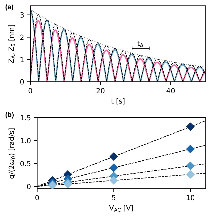
In Fig. 3, we experimentally investigate parametric coupling at in the absence of an external force. In Fig. 3(a), the anti-symmetric mode is initially driven to high amplitude by a resonant laser drive. The laser drive is then switched off and a parametric pump tone at is switched on. The two modes exchange energy periodically in additional to an overall ringdown. The theoretical fit yields a coupling frequency of , which is the highest coupling frequency we achieved with this device (for and ). In Fig. 3(b), we collect the measured values of for different and . We find a linear dependence on , while the increase in coupling frequency is stronger than linear with .
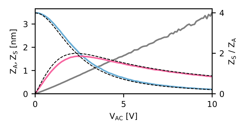
When applying a resonant laser (photon pressure) drive to mode A and a parametric pump tone at simultaneously, the system reaches an out-of-equilibrium steady state after a time [19, 17]. The amplitudes of this steady state depend on , offering an alternative way to measure the coupling. The measured and calculated results are shown in Fig. 4. For increasing parametric coupling, the steady-state amplitudes begin to equalize and cross at , whereafter mode A has the smaller amplitude of the two modes. To understand this, we need to remember that the phase of mode S follows the force exerted by the coupling term with a phase lag of , and that mode S in turn drives mode A with a second phase lag of . In total, mode A damps itself through this feedback loop, and its amplitude follows the simple closed form (see SI)
| (3) |
while the ratio between the two amplitudes is
| (4) |
We find excellent correspondence between the measurements and Eqs. (3) and (4), using and as free parameters. The value obtained for and is the same (within fit errors) as the one we found for identical conditions in Fig. 3.
The agreement between experiment and theory serves as a foundation for future applications. In particular, the linear relationship between the two mode amplitudes in Fig. 4 is an important ‘dress rehearsal’ for nuclear spin detection with a membrane resonator [17]. In this proposal, the parametric pumping is provided by an ensemble of periodically inverted nuclear spins, whose number can then be estimated from the amplitude of the undriven mode ( in Fig. 4). Our experiment shows that the parametric energy exchange between modes follows a simple mathematical form and is not significantly affected by the modes’ nonlinearities [23, 17] in the studied amplitude range.
Parametric mode conversion can also be of potential use for purely electrical applications of scanning force microscopy. For instance, a deeper understanding of the microscopic origin of mechanical damping will require highly resolved and ultrasensitive imaging of trapped charges on resonator surfaces [25, 26, 27, 28, 29, 30, 31, 32]. For a single charge, the force sensitivity of the parametric frequency conversion method (cf. Fig. 4) can be compared to the direct-drive method. Direct driving between a single surface charge and a spherical tip apex with a charge results in a Coulomb force
| (5) |
where is the permittivity of free space and the separation between the effective charge positions, with the tip apex radius. The force is the first derivative of the resonator’s electric potential in the presence of a charged tip. In contrast, the parametric method probes the second derivative of and yields
| (6) |
The two forces become equal for , which can in principle be attained for . The calculation generally shows that the two methods do not differ by much in sensitivity for . Inserting into Eq. (6) the numerical values (one elementary charge), and , we obtain . This force should be routinely detected with our ultrasensitive membrane resonators whose force noise will drop below at cryogenic temperatures [9]. Significantly higher forces can be generated by increasing the tip charge – for the self-capacitance of a sphere with radius , a tip voltage induces elementary charges. We propose to implement the direct and parametric methods simultaneously to gain access to complementary information, i.e., the first and second derivatives of the tip-surface interaction energy, to improve the determination of the electrical fields.
To conclude, we have demonstrated strong (classical) parametric coupling between two membrane modes induced by the time-dependent voltage on a scanning tip. This achievement unlocks a large toolbox that vastly increases the range of possible experiments using such resonators. First, strong mode coupling was shown to be a useful way to avoid long transient dynamics and to obtain rapid resonator control [36]. Second, our experiment serves an electrical test for parametric spin sensing experiments that will couple two resonator modes via coherently inverted nuclear spins [19, 17]. Third, our study motivates additional investigations of the membrane’s electrical surface states, allowing deeper insights into the surface chemistry and the microscopic nature of non-contact friction [9, 32]. Finally, with further improvements of the parametric coupling strength , we could accomplish quantum-coherent state transfer between nondegenerate modes. The best dissipation-limited quantum coherence times for membrane resonators are on the order of milliseconds at [11] and already exceed at dilution refrigerator temperatures [22]. This means that our experimental approach requires only a moderate improvement to overcome the decoherence stemming from dissipation, while decoherence caused by frequency noise is currently not well characterized in this system. Our scanning probe-based approach is, in addition, very flexible with regard to different modes of vibration, whose optimal coupling points (in real space) are located at different positions.
Acknowledgements.
We gratefully acknowledge technical support by the mechanical workshop of D-PHYS at ETH Zurich. This work was supported by Swiss National Science Foundation (SNSF) through the National Center of Competence in Research in Quantum Science and Technology (NCCR QSIT), the Sinergia grant (CRSII5_177198/1), and the project Grant 200020-178863, Danmarks Grundforskningsfond (DNRF) Center of Excellence Hy-Q, the European Research Council through the ERC Starting Grant Q-CEOM (grant agreement 638765), and the ERC Consolidator grant PHOQS (grant agreement 101002179), the DFG Heisenberg grant, as well as an ETH research grant (ETH-03 16-1).References
- Verbridge et al. [2008] S. S. Verbridge, H. G. Craighead, and J. M. Parpia, A megahertz nanomechanical resonator with room temperature quality factor over a million, Applied Physics Letters 92, 013112 (2008).
- Anetsberger et al. [2010] G. Anetsberger, E. Gavartin, O. Arcizet, Q. P. Unterreithmeier, E. M. Weig, M. L. Gorodetsky, J. P. Kotthaus, and T. J. Kippenberg, Measuring nanomechanical motion with an imprecision below the standard quantum limit, Phys. Rev. A 82, 061804(R) (2010).
- Reetz et al. [2019] C. Reetz, R. Fischer, G. Assumpção, D. McNally, P. Burns, J. Sankey, and C. Regal, Analysis of membrane phononic crystals with wide band gaps and low-mass defects, Physical Review Applied 12, 044027 (2019).
- Reinhardt et al. [2016] C. Reinhardt, T. Müller, A. Bourassa, and J. C. Sankey, Ultralow-noise sin trampoline resonators for sensing and optomechanics, Phys. Rev. X 6, 021001 (2016).
- Tsaturyan et al. [2017] Y. Tsaturyan, A. Barg, E. S. Polzik, and A. Schliesser, Ultracoherent nanomechanical resonators via soft clamping and dissipation dilution, Nature Nanotechnology 12, 776 (2017).
- Ghadimi et al. [2018] A. H. Ghadimi, S. A. Fedorov, N. J. Engelsen, M. J. Bereyhi, R. Schilling, D. J. Wilson, and T. J. Kippenberg, Elastic strain engineering for ultralow mechanical dissipation, Science 360, 764 (2018).
- Beccari et al. [2021a] A. Beccari, M. J. Bereyhi, R. Groth, S. A. Fedorov, A. Arabmoheghi, N. J. Engelsen, and T. J. Kippenberg, Hierarchical tensile structures with ultralow mechanical dissipation (2021a), arXiv:2103.09785 .
- Beccari et al. [2021b] A. Beccari, D. A. Visani, S. A. Fedorov, M. J. Bereyhi, V. Boureau, N. J. Engelsen, and T. J. Kippenberg, Strained crystalline nanomechanical resonators with ultralow dissipation (2021b), arXiv:2107.02124 .
- Hälg et al. [2021] D. Hälg, T. Gisler, Y. Tsaturyan, L. Catalini, U. Grob, M.-D. Krass, M. Héritier, H. Mattiat, A.-K. Thamm, R. Schirhagl, E. C. Langman, A. Schliesser, C. L. Degen, and A. Eichler, Membrane-based scanning force microscopy, Phys. Rev. Applied 15, L021001 (2021).
- Peterson et al. [2016] R. W. Peterson, T. P. Purdy, N. S. Kampel, R. W. Andrews, P.-L. Yu, K. W. Lehnert, and C. A. Regal, Laser cooling of a micromechanical membrane to the quantum backaction limit, Phys. Rev. Lett. 116, 063601 (2016).
- Rossi et al. [2018] M. Rossi, D. Mason, J. Chen, Y. Tsaturyan, and A. Schliesser, Measurement-based quantum control of mechanical motion, Nature 563, 53 (2018).
- Mason et al. [2019] D. Mason, J. Chen, M. Rossi, Y. Tsaturyan, and A. Schliesser, Continuous force and displacement measurement below the standard quantum limit, Nature Physics 15, 745 (2019).
- Page et al. [2021] M. A. Page, M. Goryachev, H. Miao, Y. Chen, Y. Ma, D. Mason, M. Rossi, C. D. Blair, L. Ju, D. G. Blair, A. Schliesser, M. E. Tobar, and C. Zhao, Gravitational wave detectors with broadband high frequency sensitivity, Communications Physics 4 (2021).
- Bagci et al. [2014] T. Bagci, A. Simonsen, S. Schmid, L. G. Villanueva, E. Zeuthen, J. Appel, J. M. Taylor, A. Sørensen, K. Usami, A. Schliesser, and E. S. Polzik, Optical detection of radio waves through a nanomechanical transducer, Nature 507, 81 (2014).
- Andrews et al. [2014] R. W. Andrews, R. W. Peterson, T. P. Purdy, K. Cicak, R. W. Simmonds, C. A. Regal, and K. W. Lehnert, Bidirectional and efficient conversion between microwave and optical light, Nature Physics 10, 321 (2014).
- Fischer et al. [2019] R. Fischer, D. P. McNally, C. Reetz, G. G. T. Assumpção, T. Knief, Y. Lin, and C. A. Regal, Spin detection with a micromechanical trampoline: towards magnetic resonance microscopy harnessing cavity optomechanics, New Journal of Physics 21, 043049 (2019).
- Košata et al. [2020] J. Košata, O. Zilberberg, C. L. Degen, R. Chitra, and A. Eichler, Spin detection via parametric frequency conversion in a membrane resonator, Phys. Rev. Applied 14, 014042 (2020).
- Boyd [2020] R. W. Boyd, Nonlinear optics (Academic press, 2020).
- Dougherty et al. [1996] W. M. Dougherty, K. J. Bruland, J. L. Garbini, and J. A. Sidles, Detection of ac magnetic signals by parametric mode coupling in a mechanical oscillator, Meas. Sci. Technol. 7, 1733–1739 (1996).
- Faust et al. [2013] T. Faust, J. Rieger, M. J. Seitner, J. P. Kotthaus, and E. M. Weig, Coherent control of a classical nanomechanical two-level system, Nature Physics 9, 485 (2013).
- Okamoto et al. [2013a] H. Okamoto, A. Gourgout, C.-Y. Chang, K. Onomitsu, I. Mahboob, E. Y. Chang, and H. Yamaguchi, Coherent phonon manipulation in coupled mechanical resonators, Nat. Phys. 9, 480 (2013a).
- Seis et al. [2021] Y. Seis, T. Capelle, E. Langman, S. Saarinen, E. Planz, and A. Schliesser, Ground state cooling of an ultracoherent electromechanical system (2021), arXiv:2107.05552 .
- Catalini et al. [2020] L. Catalini, Y. Tsaturyan, and A. Schliesser, Soft-clamped phononic dimers for mechanical sensing and transduction, Phys. Rev. Applied 14, 014041 (2020).
- Unterreithmeier et al. [2009] Q. P. Unterreithmeier, E. M. Weig, and J. P. Kotthaus, Universal transduction scheme for nanomechanical systems based on dielectric forces, Nature 458, 1001 (2009).
- Camp et al. [1991] J. B. Camp, T. W. Darling, and R. E. Brown, Macroscopic variations of surface potentials of conductors, Journal of Applied Physics 69, 7126 (1991).
- Burnham et al. [1992] N. A. Burnham, R. J. Colton, and H. M. Pollock, Work-function anisotropies as an origin of long-range surface forces, Physical Review Letters 69, 144 (1992).
- Rossi and Opat [1992] F. Rossi and G. I. Opat, Observations of the effects of adsorbates on patch potentials, Journal of Physics D: Applied Physics 25, 1349 (1992).
- Speake and Trenkel [2003] C. C. Speake and C. Trenkel, Forces between conducting surfaces due to spatial variations of surface potential, Physical Review Letters 90, 160403 (2003).
- Gaillard et al. [2006] N. Gaillard, M. Gros-Jean, D. Mariolle, F. Bertin, and A. Bsiesy, Method to assess the grain crystallographic orientation with a submicronic spatial resolution using kelvin probe force microscope, Applied Physics Letters 89, 154101 (2006).
- Robertson et al. [2006] N. A. Robertson, J. R. Blackwood, S. Buchman, R. L. Byer, J. Camp, D. Gill, J. Hanson, S. Williams, and P. Zhou, Kelvin probe measurements: investigations of the patch effect with applications to ST-7 and LISA, Classical and Quantum Gravity 23, 2665 (2006).
- Zúñiga-Pérez et al. [2005] J. Zúñiga-Pérez, V. Muñoz-Sanjosé, E. Palacios-Lidón, and J. Colchero, Polarity effects on zno films grown along the nonpolar direction, Physical Review Letters 95, 226105 (2005).
- Héritier et al. [2021] M. Héritier, R. Pachlatko, Y. Tao, J. M. Abendroth, C. L. Degen, and A. Eichler, Spatially resolved surface dissipation over metal and dielectric substrates (2021), arXiv:2104.02437 .
- [33] See supplemental material at [url will be inserted by publisher] for additional discussions on the surface charge, data of a second device, the derivation of the coupling process and driving at the frequency sum.
- Frimmer and Novotny [2014] M. Frimmer and L. Novotny, The classical bloch equations, Am. J. Phys 82, 947–954 (2014).
- Okamoto et al. [2013b] H. Okamoto, A. Gourgout, C.-Y. Chang, K. Onomitsu, I. Mahboob, E. Y. Chang, and H. Yamaguchi, Coherent phonon manipulation in coupled mechanical resonators, Nature Physics 9, 480 (2013b).
- Okamoto et al. [2014] H. Okamoto, I. Mahboob, K. Onomitsu, and H. Yamaguchi, Rapid switching in high-q mechanical resonators, Applied Physics Letters 105, 083114 (2014).