On Inverse Inertia Matrix and Contact-Force Model for Robotic Manipulators at Normal Impacts
Abstract
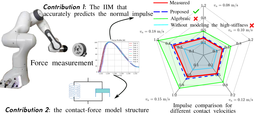
State-of-the-art impact dynamics models either apply for free-flying objects or do not account that a robotic manipulator is commonly high-stiffness controlled. Thus, we lack tailor-made models for manipulators mounted on a fixed base. Focusing on orthogonal point-to-surface impacts (no tangential velocities), we revisit two main elements of an impact dynamics model: the contact-force model and the inverse inertia matrix. We collect contact-force measurements by impacting a 7 DOF Panda robot against a sensorized rigid environment with various joint configurations and velocities. Evaluating the measurements from 150 trials, the best model-to-data matching suggests a viscoelastic contact-force model and computing the inverse inertia matrix assuming the robot is a composite-rigid body.
Index Terms:
Contact modeling, impact-awareness, dynamics.I Introduction
When a high-stiffness controlled robot impacts rigid surfaces, the robot’s joint velocities and torques values will change instantly, within a fraction to dozens of milliseconds. If not restricted to their tolerable range, such state jumps may have severe consequences, up to damaging the robot’s hardware and/or its surroundings. Therefore, close-to-zero contact velocity is generally planned to avoid impacts, e.g., [1]. This workaround, however, prevents implementing impact-based tasks like hammering, dynamic loco-manipulations, or heavy box swift grabbing, to name just a few. A reliable impact dynamics model would allow the robot controller to regulate the contact velocities according to predicted post-impact states.
State-of-the-art robot controllers, e.g., [2, 3, 4] predicts impact subsequent impulses using the algebraic equations developed in the late 1980s [5]. Impact studies such in [6, 7, 8] proposed more refined models, yet most of them assume impacts between two free-flying bodies [9].
Under active-continuous joint control, fixed-base manipulators will not bounce as a free-floating mass would have done. In front of the difficulty of having reliable and sound impact predictions using textbook models, we investigate the reasons for this shortcoming. Therefore, we devised a benchmark study using the Panda robot in a well-calibrated and instrumented environment, see Fig. 1.
Predicting the post-impact states relies on (at least) two essential ingredients: (i) a good estimate or the computation of the task-space velocity-to-impulse mapping, i.e., the inverse inertia matrix (IIM), and (ii) a contact-force model.
A well-defined IIM [6] allows predicting (a) the post-impact contact mode (i.e., sliding or sticking), (b) the stable slip direction (i.e., if the tangential contact velocity converged to an invariant direction), and (c) the contact velocity given an impulse (during an impact event). We theoretically derive the IIM based on different assumptions:
- 1.
-
2.
considering the joints with high-stiffness, hence treating the robot as a composite-rigid body (CRB);
- 3.
According to the data collected from 150 impact experiments, our findings suggest that we can predict the normal impulse most accurately with option (2).
Different contact-force models lead to drastically different timing of the events, e.g., the end of compression or, more importantly, the end of restitution, which determines the impulse and post-impact velocities [7, 8]. Based on the measured contact forces, we found the deformation-rate-dependent (viscoelastic) compliance is not negligible, i.e., the pure elastic contact-force model for two free-flying bodies [7, 14] [6, Chapter 2] is not applicable for high-stiffness controlled manipulators. The viscoelasticity enables representing energy-dissipation by damping and indicates a decreasing estimated coefficient of restitution (COR) when the contact velocity increases [6]. In all the experiments, the estimated COR is smaller than the material-dependent COR.
To summarize, for the impacts conducted by a high-stiffness controlled manipulator, our findings are:
- 1.
-
2.
the contact-force model is viscoelastic, see Sec. V.
Our analysis is based on the following assumptions:
-
•
The impact force is large compared to body forces and centripetal inertial terms. Other forces remain constant during impact [6, Chapter 8.1.1].
-
•
Point contact. The contact area is negligibly small compared to the robot dimensions [15].
- •
- •
-
•
The fixed-base fully-actuated robot under high sampling rate, e.g., 1000 Hz position/velocity control.
-
•
The impacting bodies in our experiments are locally deformable for the chosen range of contact velocities between m/s.
II Related work
The IIM is essential to predict post-impact states in rigid-body dynamics, e.g., [5, 16, 17, 11, 6, 12, 13, 7, 9, 8]. There are impact computations dealing specifically with non-articulated objects, e.g., [16, 6, 7, 9, 8], or articulated linkages yet without accounting for the controller behavior, e.g., the under-actuated pendulums studied by [11, 12, 18] with experiments and by [17, 13] in simulation. According to our benchmark experiments, both situations do not accurately predict the impulse (between a high-stiffness controlled manipulator and the rigid environment). Our IIM computation accounts for both the robot joint motion constraints [17, 11, 12, 13, 18]; and the high-stiffness aspect by assuming the robot is a composite-rigid body during the short time span of an impact.
The mass-spring-damper model is widely adopted to describe the normal contact force [14]. Elasticity is commonly used for impacts between free-flying bodies [6, 7, 19]. However, pure elasticity contradicts the fact that our measured peak force is not in phase with the compression. According to our benchmark experiments, the viscoelastic models reported by Stronge in [6] determine the impact events more accurately for robot under high-stiffness joint control. There are many continuous point-contact force models [20]. However, the model parameters might change regarding different control modes, and the inclusion of the contact-force model in the equations of motion may result in computational inefficiency or failure of numerical integration routines [11]. Thus, we focus on identifying the model structure, i.e., linear spring and nonlinear dashpot, without explicitly comparing the best-fit model from all the candidates.
III Notations
We define the IIM and introduce commonly-applied computations in the rest of the paper.
Definition 1
Assuming impact does not generate impulsive moment, we evaluate the contact velocity jump during the impact via the inverse inertia matrix and the impulse [6]:
| (1) |
We borrow the notations from the book by Murray et al. [21]. To ease the reading, we mark the body velocities and associated Jacobians in cyan, e.g., the body velocity of link (with respect to the inertial frame and represented in the link frame ) is111Since we use only body velocities, we omit the subscript b; is noted by in [21]. , which concatenates the linear velocity and the rotational velocity :
We mark the adjoint transform and its expansions by blue color.
In the rest of the paper, we apply the following velocity, wrench and inertia transforms:
(1): Transform the body velocity to frame :
| (2) |
where denote the relative rotation and the relative translation, respectively. The skew-symmetric matrix converts the cross product by matrix multiplication.
(2): Transform the wrench represented in frame to frame :
| (3) |
Note that momentum transform is the same as (3) [22].
(3): Transform the inertia matrix represented in frame to frame :
| (4) |
IV The Inverse Inertia Matrix
We studied three ways to compute : (1) inverse of the generalized (joint-space) momentum in Sec. IV-A, (2) assuming the robot is a composite-rigid body (CRB) in Sec. IV-B, (3) without considering joints’ high-stiffness in Sec. IV-C. We leave the details of computing the normal impulse with a particular IIM in Appendix -A.
IV-A Projection Approach
From the principle of kinetic energy conservation, the body velocity and the equivalent inertia matrix produce the same amount of kinetic energy as the joint space inertia matrix and velocities
| (5) |
We denote by in (5-7) to avoid lengthy notations. The equality (5) leads to two options222We reserve the first 3 rows for translational velocity of the Jacobian . If the notations are in line with the book by Featherstone [22], we need to take the lower-right corner. to compute the impulse:
| (6) | ||||
| (7) |
IV-B Composite-rigid-body approach
Let be the external force applied at contact point . The wrench at the th link writes:
| (9) |
Given the mass and the moment of inertia , Newton-Euler’s equation in the body coordinates writes:
| (10) |
where is an identity matrix. Substituting (9) into (10), we compute the momentum jump by integrating (10) over the impact duration
| (11) |
where the cross product in (10) vanishes as the impact force is large w.r.t the centripetal inertial terms [6, Chapter 8.1.1].
In order to compute the impact-induced whole-body momentum jump, we transform each to the centroidal frame according to (3) and aggregate the transformed momentum jump of all the links:
| (12) |
The jump of the average velocity [23, Eq. 24] defined in the centroidal frame writes:
| (13) |
where the centroidal inertia is similar to [23, Eq. 22]. The relation between and the inertia matrix of a specific link is explained in Appendix -B1.
We re-write the contact point body velocity relative to the centroidal frame (which is between the inertial frame and the contact point frame ) according to [21, Proposition 2.15]:
| (14) |
The CRB assumption leads to the relative velocity between the centroidal frame and the contact point is zero () such that we can approximate:
| (15) |
which amounts to transforming the average velocity to the contact point according to the velocity transform (2). Substituting from (13) into (15), the contact point velocity jump induced by the external impulse is:
| (16) | ||||
Given , we extract the translation from (16) and obtain the inverse inertia matrix:
| (17) |
where is the robot’s total mass, is the moment of inertia of .
Remark IV.1
Remark IV.2
We denote the inertia matrix of the link as . The contribution of to is:
| (19) |
where is the transform from the contact point frame to the end-effector frame ; see Appendix -B.
IV-C Without considering high-stiffness
V The contact force model
The nonlinear viscoelastic model in Sec. V-A, can generate measurement-consistent contact forces. It predicts a decreasing COR if the contact velocity increases, see Sec. V-B. It also models the energy loss via the dissipated energy and the non-zero potential energy at the end of restitution, see Sec. V-C.
V-A Contact-force model
We use the viscoelastic model in [6, Sec. 5.1.2] at contact point . Let be the normal relative deformation, see Fig. 5(a), we choose the local coordinate frame such that the initial normal contact velocity is negative: . The normal contact-force is the derivative of the normal impulse :
| (23) |
where the positive scalars and denote the dashpot coefficient and the spring constant.
V-B Coefficient of restitution
Using an impact model with the COR, the velocity when the restitution ends is
| (24) |
The deformation keeps negative during the impact but does not restore to (initial) zero by the end of the restitution phase, see Fig. 7 and Sec. VII. Yet, at the end of the restitution, the contact force is almost nil. Equating (23) to zero leads
and substituting from (24), we conclude another expression of COR:
| (25) |
Therefore, if is constant, decreases if the pre-impact contact velocity increases.
V-C Energy consistency
At any instant of the impact process, the sum of the kinetic energy , the spring-stored potential energy
| (26) |
and the dashpot dissipated energy
| (27) |
is always equal to the initial kinetic energy:
| (28) |
We can assess (28) by checking its derivative: , and , we find:
At the end of the impact process, the energy loss includes the remaining potential energy and the dissipated energy .
VI Data acquisition
To keep the point contact assumption, a custom-made 3D-printed semi-spherical rigid piece is mounted on the end-effector of the 7 DOF panda robot. The robot is controlled in velocity command to impact an ATI-mini45 force-torque sensor fixed at different spots of a rigid wall. The controller loop runs at ms, which is about one-tenth of the average impact duration observed in our experiments. The material-dependent COR is estimated to be 333https://gite.lirmm.fr/yuquan/fidynamics/-/wikis/Estimating-the-material-dependent-coefficient-of-restitution.. We applied the following reference contact velocities: m/s, m/s, m/s, m/s, m/s for three distinct configurations, see Fig. 2. We repeated 10 times each combination. Hence, the dataset includes experiments.
We sample the force-torque sensor at kHz to capture the dynamics of low-velocity impacts, see the 40 contact-force profiles in Fig. 6. The Panda robot has a torque sensor on each joint. Once the impact is detected by thresholding the joint torques, the robot controller immediately pulls back the end-effector to avoid redundant post-impact actions. For the three impact configurations, we noticed significant impact-induced joint torque errors associated with the 5th and 6th joint. Thus, we detect the impact by thresholding:
where the QP controller updates the reference at each control cycle. The threshold is Nm for configuration one and two; Nm for configuration three.
We have the ground-truth impact-timing from the force-torque sensor. The measured forces do not suffer from motion-dependent drift as the sensor is rigidly attached to the wall. We achieved to ms detection time, which is comparable to the state-of-the-art collision detection time: ms [25].
| (a) Configuration one (b) Configuration two (c) Configuration three |
VII Experimental Results Dicussion
Confronting the models to the obtained measurements, we found the followings:
c1: only the nonlinear viscoelastic model regenerates measured contact forces and theory-consistent COR; see Sec. VII-A.
c2: the proposed IIM computation (17) is the most accurate; see Sec. VII-B.
According to c1, we claim the following remarks:
r1: the pure material-dependent COR does not apply for high-stiffness controlled manipulators, see Fig. 5(b),
r2: Since the virtual spring model is not adequate, the following assumptions that are applied in [7, 9] are not applicable for robot impacts:
(1) the potential energy reaches the peak at maximum contact force;
(2) the compression restores to zero when the restitution ends.
To verify if the impact (or restitution) ends, we check if the contact force (23) restores to zero. We also observed that if the conditions in Sec. VII-C are met, we can apply a COR smaller than for our experiment setup.
VII-A Contact force model
The virtual-spring model does not fit measured contact-force profiles unless the COR is greater than 1, see Sec. VII-A1). The Maxwell model assumes that the COR remains unchanged regardless of the contact velocities. However, this assumption contradicts the data, see Sec. VII-A2. The candidate nonlinear viscoelastic model can match the measured contact-force profile with a theory-consistent COR, see Sec. VII-A3.
VII-A1 The virtual spring model
According to the virtual spring in Fig. 3(a), the contact force and the compression should be perfectly in phase; that is to say, the maximum contact force is reached when the compression ends. Therefore, the contact-force profile during restitution should be within the blue area in Fig. 3(b) according to [6, Chapter 2.2]. Yet, the virtual-spring model does not fit the measured contact profiles unless the coefficient of restitution ! This observation is not limited to Fig. 3(b), and similar patterns are found in other contact-force profiles shown in Fig. 6.
Thus, the virtual spring model is not suitable. The contact force shall be out-of-phase with the compression by some angle; i.e., the peak contact force occurs ahead of the maximum compression.
| (a) The virtual spring model (b) Requires COR greater than 1 |
VII-A2 The Maxwell model
We illustrate the Maxwell model (series connection of a spring with stiffness and a dashpot with constant ), see Fig. 4(a). The complete linear second-order system is detailed in [6, Chapter 5.1.1]. Measured contact-force profiles are exploited to identify , , and COR according to [6, Eq 5.7], using MATLAB estimation toolbox. The estimated COR should be invariant with respect to the increasing contact velocities. However, according to Fig. 4(b), this is not the case. In this case, the Maxwell model is also not suitable.
| (a) Maxwell contact-force model (b) Contact velocity dependent COR |
VII-A3 The nonlinear viscoelastic model
Similarly to Sec. VII-A2, we identified and for the nonlinear viscoelastic model (23); see [6, Chapter 5.1.2].
We overlay the model-generated contact-force profiles on the measurements in Fig. 7. Because of the viscoelasticity, the compression might not fully restore to zero by the end of the restitution phase.
According to (25), the COR should decrease while the contact velocity increases, which is mostly true in Fig. 5(b). The exception happened at the second impact configuration when the reference contact velocity is m/s.
The spring model in Fig. 3(a) cannot capture the energy dissipation. It entirely relies on the COR to model the energy loss. For instance, it relies on a sudden decrease of the potential energy by when the compression phase ends [9, Eq. 11, Fig. 3.(h)]. Due to the dashpot, we can explicitly and continuously describe the potential, kinetic, and dissipated energy along with their derivatives; see the equations in Sec. V-C and the plots in Fig. 8.
| (a) The contact-force model | (b) Theory-consistent COR |
VII-B Candidate inverse inertia matrices
We compute the impulse444The impulse does not rely on COR as it corresponds to the moment when the compression ends. using different options:
- 1.
- 2.
- 3.
- 4.
Option 1 overestimates in all the situations as shown in Fig. 9. Hence, computation according to kinetic energy conservation in the joint space (5) is not a good hypothesis. Options 2 and 4 lead to similar results: both showing underestimated performance. Thus, we cannot assume the joints are completely flexible in the joint motion subspace, as in the under-actuated pendulum by Lankarani [11] or the under-actuated linkage by Stronge [6, Example 8.1].
Option 3 leads to the most accurate prediction. Therefore, the CRB assumption applies to a high-stiffness-controlled manipulator.
VII-C Small coefficient of restitution
| Reference: | 0.08 m/s | 0.10 m/s | 0.12 m/s | 0.15 m/s | 0.18 m/s |
| Exact: . | |||||
| Fig. 2(a) | 0.0756 | 0.0956 | 0.1156 | 0.1456 | 0.1755 |
| Fig. 2(b) | 0.0745 | 0.0943 | 0.1141 | 0.1438 | 0.1734 |
| Fig. 2(c) | 0.0715 | 0.0913 | 0.1111 | 0.1411 | 0.1709 |
| Approximation: . | |||||
| Fig. 2(a) | 0.0699 | 0.0870 | 0.1056 | 0.1309 | 0.1623 |
| Fig. 2(b) | 0.0567 | 0.0734 | 0.0975 | 0.1239 | 0.1486 |
| Fig. 2(c) | 0.0446 | 0.0586 | 0.0712 | 0.0894 | 0.1036 |
| Approximate-to-exact ratio: . | |||||
| Fig. 2(a) | 0.9248 | 0.9100 | 0.9141 | 0.8996 | 0.9243 |
| Fig. 2(b) | 0.7609 | 0.7785 | 0.8544 | 0.8618 | 0.8567 |
| Fig. 2(c) | 0.6244 | 0.6423 | 0.6406 | 0.6336 | 0.6062 |
Given the linear relative velocity and the impact normal , we define the approximate-to-exact ratio as:
| (29) |
The smaller the projection , the higher .
According to the numerical values in Table I and the corresponding estimated COR in Fig. 5(b), we observe that it is possible to assume (i.e., approximately inelastic impact) in our experiments if the following are met:
(1) when the relative velocity is close to zero, e.g., when the approximate-to-exact ratio ;
(2) the contact velocity is greater than m/s.
VIII Conclusion
Our objective is to devise an impact-aware controller for high-stiffness controlled robotic manipulators based on models, whether physics-driven or data-driven. Our dataset of 150 impact experiments revealed the short-comings of the most-used models. Thus, we revisit two main ingredients:
-
•
the inverse inertia matrix (IIM) computation that determines the effective mass (velocity-to-impulse mapping) at the impact and post-impact contact modes, and
-
•
the contact-force model that determines the impact event timing, namely that of the restitution phase.
Our findings suggest that
-
1.
one shall compute the inverse inertia matrix (IIM) as the inverse of the composite-rigid-body inertia transformed at the contact point, see Sec. IV-B;
- 2.
-
3.
the viscoelastic contact-force model (parallel connection of a virtual spring and a dashpot) in Sec. V-A matches the measurements while fulfilling its assumptions.
In future work, we aim at accurately predicting the post-impact states when the contact surface is frictional and the tangential contact velocity is significant.
| (a) Impulses corresponding to Fig. 2(a) (b) Impulses corresponding to Fig. 2(b) (c) Impulses corresponding to Fig. 2(c) |
Appendix
-A Normal impulse computation
The impact process consists of two sequential phases: compression and restitution [7]. The compression ends when the normal contact velocity increases from to zero. To check the evolution of , we compute its derivative:
where the vector denotes the impact normal, the subscript denotes the quantity is projected to the tangential plane. Due to the assumption of a small friction coefficient, the tangential impulse is negligible. Thus, we have . The contact velocity monotonically increases according to:
| (30) |
which holds due to the positive definiteness of [9]. Integrating (30) by separating and on two sides, the impulse writes:
| (31) |
where we defined the positive scalar . At the moment when , we conclude the end of compression impulse:
| (32) |
-B Proof of remark IV.2
We prove (19) by the derivation in Appendix -B1, and the analysis of a particular inertia matrix in Appendix -B2.
-B1 Centroidal inertia derivation
-B2 Contribution of a particular inertia matrix
Acknowledgment
We thank J. Roux, P. Gergondet, S. Samadi, M. Djeha and O. Tempier for helping in the experiments. We also thank our colleagues from the I.AM. consortium for their feedback.
References
- [1] A. W. Winkler, C. D. Bellicoso, M. Hutter, and J. Buchli, “Gait and trajectory optimization for legged systems through phase-based end-effector parameterization,” IEEE Robotics and Automation Letters, vol. 3, no. 3, pp. 1560–1567, 2018.
- [2] J. W. Grizzle, C. Chevallereau, R. W. Sinnet, and A. D. Ames, “Models, feedback control, and open problems of 3d bipedal robotic walking,” Automatica, vol. 50, no. 8, pp. 1955–1988, 2014.
- [3] B. Siciliano and O. Khatib, Springer handbook of robotics. Springer, 2016.
- [4] Y. Wang, D. Niels, A. Tanguy, and A. Kheddar, “Impact-aware task-space quadratic-programming control,” 2020. [Online]. Available: https://arxiv.org/pdf/2006.01987.pdf
- [5] Y.-F. Zheng and H. Hemami, “Mathematical modeling of a robot collision with its environment,” Journal of Field Robotics, vol. 2, no. 3, pp. 289–307, 1985.
- [6] W. J. Stronge, Impact mechanics. Cambridge university press, 2000.
- [7] Y.-B. Jia and F. Wang, “Analysis and computation of two body impact in three dimensions,” Journal of Computational and Nonlinear Dynamics, vol. 12, no. 4, 2017.
- [8] M. Halm and M. Posa, “Modeling and analysis of non-unique behaviors in multiple frictional impacts,” in Robotics: Science and Systems, Freiburg, Germany, 2019.
- [9] Y.-B. Jia, M. Gardner, and X. Mu, “Batting an in-flight object to the target,” The Int. Journal of Robotics Research, vol. 38, no. 4, pp. 451–485, 2019.
- [10] I. Aouaj, V. Padois, and A. Saccon, “Predicting the post-impact velocity of a robotic arm via rigid multibody models: an experimental study,” in IEEE Int. Conf. on Robotics and Automation, 2021, pp. 2264–2271.
- [11] H. M. Lankarani, “A poisson-based formulation for frictional impact analysis of multibody mechanical systems with open or closed kinematic chains,” Journal of Mechanical Design, vol. 122, no. 4, pp. 489–497, 2000.
- [12] Y. Khulief, “Modeling of impact in multibody systems: an overview,” Journal of Computational and Nonlinear Dynamics, vol. 8, no. 2, 2013.
- [13] F. Aghili and C.-Y. Su, “Impact dynamics in robotic and mechatronic systems,” in IEEE Int. Conf. on Advanced Mechatronic Systems, 2017, pp. 163–167.
- [14] S. Pashah, M. Massenzio, and E. Jacquelin, “Prediction of structural response for low velocity impact,” Int. Journal of Impact Engineering, vol. 35, no. 2, pp. 119–132, 2008.
- [15] A. Chatterjee and A. Ruina, “A new algebraic rigid-body collision law based on impulse space considerations,” Journal of Applied Mechanics, vol. 65, no. 4, pp. 939–951, 1998.
- [16] Y. Wang and M. T. Mason, “Two-dimensional rigid-body collisions with friction,” Journal of Applied Mechanics, vol. 59, no. 3, pp. 635–642, 1992.
- [17] Y. Hurmuzlu and D. B. Marghitu, “Rigid body collisions of planar kinematic chains with multiple contact points,” The Int. Journal of robotics research, vol. 13, no. 1, pp. 82–92, 1994.
- [18] S. Ganguly and O. Khatib, “Contact-space resolution model for a physically consistent view of simultaneous collisions in articulated-body systems: theory and experimental results,” The Int. Journal of Robotics Research, vol. 39, no. 10-11, pp. 1239–1258, 2020.
- [19] N. Dehio and A. Kheddar, “Robot-safe impacts with soft contacts based on learned deformations,” in IEEE Int. Conf. on Robotics and Automation, 2021, pp. 1357–1363.
- [20] L. Skrinjar, J. Slavič, and M. Boltežar, “A review of continuous contact-force models in multibody dynamics,” Int. Journal of Mechanical Sciences, vol. 145, pp. 171–187, 2018.
- [21] R. M. Murray, Z. Li, S. S. Sastry, and S. S. Sastry, A mathematical introduction to robotic manipulation. CRC press, 1994.
- [22] R. Featherstone, Rigid body dynamics algorithms. Springer, 2014.
- [23] D. E. Orin, A. Goswami, and S.-H. Lee, “Centroidal dynamics of a humanoid robot,” Autonomous robots, vol. 35, no. 2-3, pp. 161–176, 2013.
- [24] Y. Wang and A. Kheddar, “Impact-friendly robust control design with task-space quadratic optimization,” in Robotics: Science and Systems, vol. 15, Freiburg, Germany, 24-26 June 2019, p. 32.
- [25] S. A. B. Birjandi, J. Kühn, and S. Haddadin, “Observer-extended direct method for collision monitoring in robot manipulators using proprioception and imu sensing,” IEEE Robotics and Automation Letters, vol. 5, no. 2, pp. 954–961, 2020.