Abstract
Achieving short-distance flight helps improve the efficiency of humanoid robots moving in complex environments (e.g., crossing large obstacles or reaching high places) for rapid emergency missions. This study proposes a design of a flying humanoid robot named Jet-HR2 (Fig. 1). The robot has 10 joints driven by brushless motors and harmonic drives for locomotion. To overcome the challenge of the stable-attitude takeoff in small thrust-to-weight conditions, the robot was designed based on the concept of thrust vectoring. The propulsion system consists of four ducted fans, that is, two fixed on the waist of the robot and the other two mounted on the feet for thrust vector control. The thrust vector is controlled by adjusting the attitude of the foot during the flight. A simplified model and control strategies are proposed to solve the problem of attitude instability caused by mass errors and joint position errors during takeoff. The experimental results showed that the robot’s spin and dive behaviors during takeoff were effectively suppressed by controlling the thrust vector of the ducted fan on the foot. The robot successfully achieved takeoff at a thrust-to-weight ratio of 1.17 (17 kg / 20 kg) and maintained a stable attitude, reaching a takeoff height of over 1000 mm.
Design of a Flying Humanoid Robot Based on Thrust Vector Control
Yuhang Li†, Yuhao Zhou†, Junbin Huang, Zijun Wang, Shunjie Zhu, Kairong Wu, Li Zheng, Jiajin Luo,
Rui Cao, Yun Zhang, , and Zhifeng Huang∗,
†
These authors contribute equally to this work.
∗
Corresponding author: Zhifeng Huang
This work was supported by the National Natural Science Foundation of China (NSFC) under Grant No. 51605098, and in part by the Natural Science Foundation of Guangdong Province, China under Grant 2021A1515011829.
The authors are with the School of Automation, Guangdong
University of Technology, Guangzhou 510006, P. R. China. zhifeng@gdut.edu.cn
I Introduction
Recently, various disaster-response humanoid robots have been invented with unique control theories and other mechanisms to overcome uneven terrain. Traditionally, humanoid robots have overcome these obstacles by stepping [1, 2] and climbing [3, 4], yet these strategies lack efficiency, especially for dangerous environments like insurmountable obstacles and geological faults. For urgent tasks in complex real scenarios, humanoid robots are expected to have dynamic aerial skills, such as high or long jumps, short-distance flights, and hovering that exceed the body length several times.

In relation to achieving good jumping performance, many methods were proposed owing to advances in actuator technologies, algorithms, and other optimizations. One approach is weight saving. Kojima et al. proposed a high-stiffness optimized mechanical structure design, and its effectiveness was proven by a prototype robot JAXON3-P that dynamically jumped 300 mm in height [5, 6]. Compared with previous JAXON series, this new structural optimization successfully reduced the frame weight by approximately 62%. Cassie [7] was designed with a concentrated mass at the pelvis, and it has lightweight legs with leaf springs and a closed kinematic chain mechanism that can jump approximately 180 mm in height. Another approach is to enhance the power where pneumatic artificial muscle (PAM) actuators were introduced [8, 9]. Taking advantage of the properties of PAM in follow-up studies [10, 11, 12], the latest musculoskeletal humanoid could accomplish sequential jumping-stepping motions. Otani et al. [13] proposed a jump method by combining active joint driving with spring behavior in an actuator to achieve countermovement jumping motion. As a representative humanoid robot, ATLAS [14] can perform standing long jump and execute complex tasks driven by hydraulic actuators.
Although state-of-the-art miniature and multi-legged robots, such as JumpRoACH [15], Stanford Doggo [16], and Solo [17] could jump multiple times higher than their size, real-sized humanoid robots in previous studies could not jump higher or farther than their own body length. Even the latest representative humanoid robot ATLAS [14] could not jump higher than its height of 1.5 m. The performance of humanoid robots is still not up to the human level, especially with an increase in mass. On the other hand, even at the human level, robots may appear helpless on loose, collapse-prone, or cliff-like terrain.
This seems to be a limitation of using purely joint actuators to generate force. Besides, the long jumping capability has not been discussed for most of the above humanoid robots. Meanwhile, the landing impact should be considered for humanoid robots in many cases, which may increase the possibility of terrain collapse.
There are some studies for introducing thruster and aerodynamic lift to improve the dynamic performance of the traditional robot. Zhao et al. [18] developed a dragon-like aerial robot based on thruster vectoring. The robot can transform in the air to fly across a narrow space by controlling gimballed pairs of ducted fans to adjust the thrust direction of each joint. Utilizing torsional spring, thruster, and flywheel, Salti-1P [19] could reach high vertical jumping agility at 2.2 m/s with a height more than 8 times its size. Researchers from IIT had a complete flying simulation on iCub [20], focusing on the control strategy and stabilization using jet turbines as thrusters. Our previous study [21] proposed a jet-powered humanoid robot, Jet-HR1, with a ducted fan installed on each foot. By maintaining a quasi-static balance, the robot could step over a ditch with a span of 450 mm (as much as 97% of the robot’s leg) in 3D stepping. These studies demonstrated the possibility of using thrust to enhance the locomotion of humanoid robots. However, to the best of our knowledge, no life-sized humanoid robot has yet achieved flight. In this study, a novel humanoid robot that can fly using a ducted fan propulsion system was developed to explore its potential value for search and rescue in complex environments.
The primary design and control challenge is to achieve the attitude stability of the robot in the air under low thrust-to-weight conditions. The design of the robot requires tradeoffs in terms of the mass distribution between the joint actuators and propulsion systems. The robot needs to ensure that the joints have sufficient power to perform tasks such as walking, but also the propulsion can meet the requirements of short flight distances and does not place excessive weight burden on the walking task. In addition, sufficient joint torque is a guarantee for adjusting the orientation when the thrust is delivered at full load. It is difficult to achieve a thrust-to-weight ratio of more than 2 or 4 for robots to meet these requirements, as is the case with conventional quadcopters.
To overcome this challenge, the robot uses controlled thrust vectoring on the feet during flight to stabilize the attitude. The main advantage of this method is that it can provide more thrust to resist gravity compared with the method that uses thrust difference to generate torque. During the flight, the direction of the thrust is actively controlled by adjusting the attitude of the feet. With this method, the dive and spin motions caused by errors in the center-of-mass distribution and joint angle during the flight of the robot are effectively suppressed.
II Mechanical Design
II-A Specifications of Jet-HR2
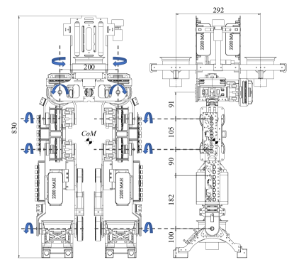
Table. II-A shows the main specifications of the prototype Jet-HR2. The robot has 10 degrees of freedom driven by brushless motor modules for ground locomotion and for adjusting the direction of the ducted fans installed in the feet during the flight. The propulsion system includes four ducted fans (Fig. 2). In addition to the two fans mounted on the palms of the feet, there are two other fans mounted at the front and rear of the waist to provide auxiliary thrust. To keep the robot lightweight, the main parts of the frame used the material of carbon fiber and ABS.
| Component | Description |
| Mass (with battery) | 17kg |
| Height | 830mm |
| Length of leg | 480mm |
| Maximum total thrust | 200N (Ducted fan x4) |
| Ducted fan |
90mm, 48V, 488g
Max thrust 50N@90A |
| Actuators (except ankle) | T-Motor Co. Ltd. U8-Lite KV150 24 V, 1.83 Nm; A-80-9, 24V, 18 Nm, 2573rpm |
| Reducer (except ankle) |
Harmonic Drive
CSF-11-50-1U-CC-SP, 50:1 |
| Actuator of ankle joints |
T-Motor Co. Ltd. A80-9
Reduction ratio 1:9, 24V Normal/Peak torque: 9Nm/ 18Nm Normal speed: 245rpm |
| Driver of actuator |
ODrive, ODrive Robotics Co. Ltd.
Ver 3.5, Can Bus |
| Ankle joint reduction ratio | 28:50 |
| Battery of motor | 6S, 22.2V, 1300 mAh |
| Battery of ducted-fan | 12S, 44.4V, 2200 mAh |
| IMU |
ASENSING CO. Ltd. INS550
250 Hz, Resolution 0.3 |
II-B Modular Joint Design
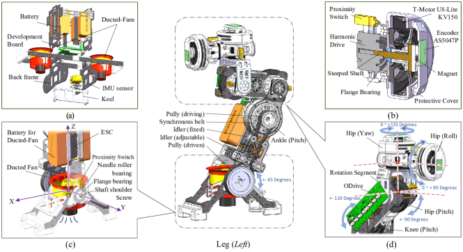
Jet-HR2 uses modular joints (Fig. 3b) for hip and knee degrees of freedom. The utilization of modular joints on robots has several advantages, including easier repair, modification, and a simplified design [22, 23]. The coordination of high-torque-density brushless motors and a harmonic drive can achieve a high output torque, accurate force/torque control precision and remains back-drivable, similar to most state-of-the-art legged robots. The modular joint in Jet-HR2 is composed of a brushless motor (T-Motor U8-Lite KV150) and a harmonic drive (CSF-11-50-1U-CC-SP). Here, we chose a high transmission ratio of 50, in which the maximum effective torque reached 30 Nm. The torque enables the robot to adjust the direction of the ducted fan installed in the feet, even when the legs are fully extended horizontally with the maximum thrust output. The estimated maximum torque caused by the ducted fan was 24 Nm. Furthermore, we integrated an absolute magnetic rotary encoder (AS5047P) placed off-axis on the protective cover to communicate with the motor controller ODrive (ODrive Robotics, Richmond, CA) based on CAN-Bus. For the initial position correction, the proximity switch is settled at the harmonic drive set printed in ABS plastic materials. In addition to high torque density and high control precision, the modular joint is compact and weighs 604 g.
II-C Leg Design
To reduce the leg inertia, which is related to the placement of the knee actuators, many optimizations have been made by previous studies, such as the Cassie [7], Minitaur [24], and MIT Cheetah series [25, 26]. These robots have the knee joint placed close to the hip joint to place the center of mass (CoM) on the higher part of the robot as much as possible. Similarly, we optimized the leg design on Jet-HR2 by aggregating the hip joint (pitch) and knee joint on the same carbon frame as integrated. Fig. 3d shows the mechanical design of the thigh part of the robot. The three-DoF hip joints are allocated separately, with the hip joint (roll) mounted on the waist. The hip joint (yaw) is located between the two carbon frames of the pelvis. In addition to reducing leg inertia, the roll-yaw-pitch configuration enables the robot to have a maximum range of motion. The hip joint (roll) could rotate 0–90°, the hip joint (yaw) could rotate 0–135°, the hip joint (pitch) ± 90°, and the knee joint ± 110°. This range of workspace could allow the robot to use its whole leg length in dynamic motions, such as stepping over a large ditch in 2D gaits [27], which contributes to enhancing the locomotion performance. The actuators on the shank are different from those of the thigh parts mentioned above. Here, we used the integrated actuator A80-9 motor (T-Motor Co. Ltd.) to satisfy the higher speed requirement for thrust vector control. We evaluated the velocity and torque on a physical simulation platform, PyBullet [28], to determine the appropriate transmission ratio for the ankle joints. The torque is transmitted to the feet of the robot through a 28:50 belt drive. The belt transmission further contributes to reducing leg inertia and helps improve the stiffness.
II-D Waist Design
The primary function of the waist frame (Fig. 3a) is to support two ducted fans and the module of roll hip joints. To save weight, the frame is mainly made of carbon fiber. The basic frame consists of an aluminum keel joining the front and back boards. The modules of the roll hip joint are mounted on the backboard to drive the entire thigh to lateral rotation. In addition, bearings are embedded in the front board, and the front of the thighs is attached by shoulder screws for support. Two ducted fans are fixed in the waist’s front and rear, respectively. To protect the ducted fans when the robot falls down, crash bars made by ABS are installed in front of the ducted fan. The IMU sensor and battery are also fixed on the waist frame.
III Model and Control Strategies
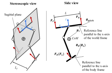
The following challenges affect the stability of the takeoff attitude. First, the robot is not perfectly centrosymmetric. The center of mass varies in the sagittal plane as the robot squats, leans forward, or leans back (Fig. 4). The difference in the force arms of the individual thrusters at the center of mass causes the robot to dive or lean back in the pitch direction. Second, owing to the interference of the ground, the thruster of the robot’s feet is not free to adjust its orientation until the feet are completely off the ground. As a result, the takeoff posture and thrust distribution should be carefully considered. Third, owing to the end thrusts, there are position control errors in the joints, which cause the robot to spin in the yaw direction because of force couples generated by errors in the direction of the thrusts.
III-A Analysis of Force Model
The model is established to analyze the forces during takeoff in a fixed position and how the robot’s attitude can be effectively adjusted in the air under low thrust-to-weight ratio conditions. The related parameters of the simplified model are listed in Table III-A. The following assumptions are made to simplify the robot model for targeted solutions to the problems of dive and yaw rotation during takeoff: 1) the robot maintains a fixed position during takeoff and is considered as a rigid body and 2) the robot legs remain parallel to each other. In other words, the components of the robot’s feet in the -axis and -axis remain the same in the body frame. 3) The pitch attitude of the ducted fans can be independently controlled in the body frame.
| Symbol | Description |
| Total mass of robot | |
| Scalar and its first order difference | |
| Vector and its components | |
| Pitch angles of right and left foot with the reference of the x-axis in body frame | |
| Pitch angle of the robot’s waist link in world frame | |
| Rotation matrix constructed by pitch world frame | |
| Thrust of ducted-fans installed in waist and feet respectively. | |
| Position of center of mass in | |
| Position of left foot’s ducted-fan in | |
| Position of right foot’s ducted-fan in | |
| Distance between front and back ducted-fan | |
| Distance between feet’s ducted fan |
Based on these assumptions, the robot becomes a 2D model in the sagittal plane. However, the feet are symmetrically distributed on both sides of the sagittal plane. Using forward kinematics, the model is expressed by the following two equations:
| (1) |
| (2) |
where
| (3) |
Equation (1) shows that all the thrusters contribute to the vertical thrust. As the pitch angle increases, some vertical thrust is lost and converted to horizontal thrust, especially because of the two fans at the waist. As a result, under conditions of a low thrust margin, the waist link should be kept as horizontal as possible during takeoff to provide vertical thrust. In addition, proper use of waist inclination can effectively counteract the horizontal thrust due to foot inclination and avoid drifting in the front or back direction during takeoff.
Equation (2) and Equation (3) describe the influence of the position of the robot’s CoM on the takeoff process. The influence is mainly in the pitch direction. Here, indicates the torque in the -direction generated by the ducted fans on the waist. To avoid generating external torque in the -direction and make the robot dive down, the thrust difference between the front and back fan output is required once is not 0. Thus, the fan at the waist does not achieve the full maximum output, resulting in a partial loss of thrust. shows the torque due to the difference in the position of the ducted fan of the feet from the CoM in the -direction. This item cannot be eliminated completely by controlling the thrust output. is caused by the position difference in the -axis between the foot’s ducted fans and the CoM. Owing to the mass distribution, this difference is significant compared with that on the -axis. Even a small horizontal thrust component in the feet can produce a significant torque. The component of shows the advantages of using thrust vector control on feet’s ducted fan to control the robot’s attitude in the pitch direction.
Fig. LABEL:fig:Fig5 compares the results of the two strategies to the general torque in the pitch direction. One is using the thrust differential (DT) between the front and rear ducted fans on the waist, similar to a multi-axis vehicle. The other is using thrust vector control (TVC) on the feet to generate pitch torque. The maximum torque that the robot can obtain at different pitch angles was used as an evaluation indicator to assess the two methods. Because of the constraint that the vertical thrust should be at least equal to the gravity, both the thrust difference or the horizontal thrust of the feet cannot achieve the maximum thrust output. Three different takeoff postures (detailed in Fig. LABEL:fig:Fig6 and Table LABEL:table:3) were compared. In all postures, the method of TVC’s boundaries of pitch torque is three times that of DT in both clockwise and counterclockwise directions. This result is mainly due to the considerable length of the force arm between CoM and the foot. The DT method requires three times the current distance between the waist fans if the same value is to be achieved. However, this would make the robot footprint too large and unrealistic.
Equation (2) also describes that the ducted fans on the feet can generate torque in the yaw and roll directions by adjusting the output and attitude difference, respectively. The control of these torques is simple because it is independent of the position of the CoM.
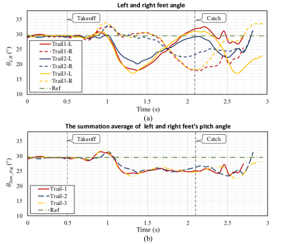
Fig. 10 describes the controller’s output on the robot’s feet corresponding to the condition when both controllers are put on (Fig. II-Aa and Fig. II-Ad). From the curve of the feet angle (Fig. 10a), it can be found that the left and right feet rotated in a different direction (about -9° and 1°) when the yaw angle decreased (1-1.4 s). This behavior created momentum to resist the movement in the yaw direction. When the yaw angle increased, feet rotated in the converse direction to counteract the effect. At 1.4 s and 2.1 s, both the yaw angle and the angle difference between the left and right feet are close to their peak. The summation average of the pitch angle of the left and right feet is calculated respectively to show the corresponding control output (Fig. 10b). According to Fig. 10b, the output of the controller and the pose performance of the robot are consistent (Fig. II-Aa). While the robot tilted back less than 1° at 1 s, the feet rotated about 2° to suppress it. After 1.3 s, the summation average angle of feet gradually stabilized near 25° with the pitch angle of the robot stabilized near 5°.
Several phenomena and issues remain to be noted and considered in the experimental results. There are steady-state errors in the pitch direction. This might be due to the configuration of the robot and the anterior-posterior asymmetry of the center of mass in the sagittal plane. Adding the integral term might improve the problem. It is worth noting that even with the presence of steady-state errors, the robot did not drift significantly back and forth during takeoff. This may indicate that the desired angle to maintain hover or takeoff is not perfectly horizontal due to the structure of the robot. Another phenomenon worth noting is that the robot dives forward rapidly when the controllers are all off, but there is no significant rotation in the yaw direction. An explanation of this phenomenon awaits a more specific kinetic analysis to follow. The experiments also showed that the roll direction does not tilt significantly because of the left-right symmetry of the robot, but there is a certain amount of drifting, which needs to be solved by adding further sensors and improving the controller.
V Conclusion
In this study, a flying humanoid robot based on the concept of thrust vector control was designed. A simplified force model was used to analyze how to maintain attitude stability during the robot’s takeoff. In the analysis, we also compared the two methods that generated the deflection torque in the pitch direction. The results indicate that using thrust vector control on the ducted fan of the feet can generate a considerable torque in the pitch direction. The results of the takeoff experiments with the prototype robot showed that the robot performed as expected. The robot achieved a successful takeoff under low thrust-to-weight ratio conditions. Moreover, the control strategy was effective in keeping the robot attitude stable during the takeoff.
The main contributions of this study are summarized as follows:
1) Our newly designed humanoid robot system successfully achieved a fully controllable takeoff, which provides a new reference for research on flight methods for humanoid robots.
2) The control strategy of the TVC on the robot’s feet was proposed, and its effectiveness was experimentally proved. This provides a reference for the attitude stabilization methods under low thrust-to-weight ratio conditions.
References
- [1] K. Kaneko, M. Morisawa, S. Kajita, S. Nakaoka, T. Sakaguchi, R. Cisneros, and F. Kanehiro, “Humanoid robot hrp-2kai—improvement of hrp-2 towards disaster response tasks,” in 2015 IEEE-RAS 15th International Conference on Humanoid Robots (Humanoids). IEEE, 2015, pp. 132–139.
- [2] T. Jung, J. Lim, H. Bae, K. K. Lee, H.-M. Joe, and J.-H. Oh, “Development of the humanoid disaster response platform drc-hubo+,” IEEE Transactions on Robotics, vol. 34, no. 1, pp. 1–17, 2018.
- [3] T. Yoshiike, M. Kuroda, R. Ujino, H. Kaneko, H. Higuchi, S. Iwasaki, Y. Kanemoto, M. Asatani, and T. Koshiishi, “Development of experimental legged robot for inspection and disaster response in plants,” in 2017 IEEE/RSJ International Conference on Intelligent Robots and Systems (IROS). IEEE, 2017, pp. 4869–4876.
- [4] T. Yoshiike, M. Kuroda, R. Ujino, Y. Kanemoto, H. Kaneko, H. Higuchi, S. Komura, S. Iwasaki, M. Asatani, and T. Koshiishi, “The experimental humanoid robot e2-dr: A design for inspection and disaster response in industrial environments,” IEEE Robotics & Automation Magazine, vol. 26, no. 4, pp. 46–58, 2019.
- [5] K. Kojima, Y. Kojio, T. Ishikawa, F. Sugai, Y. Kakiuchi, K. Okada, and M. Inaba, “A robot design method for weight saving aimed at dynamic motions: Design of humanoid jaxon3-p and realization of jump motions,” in 2019 IEEE-RAS 19th International Conference on Humanoid Robots (Humanoids). IEEE, 2019, pp. 586–593.
- [6] K. Kojima, Y. Kojio, T. Ishikawa, F. Sugai, Y. Kakiuchi, K. Okada, and M. Inaba, “Drive-train design in jaxon3-p and realization of jump motions: Impact mitigation and force control performance for dynamic motions,” in 2020 IEEE/RSJ International Conference on Intelligent Robots and Systems (IROS). IEEE, 2020, pp. 3747–3753.
- [7] X. Xiong and A. D. Ames, “Bipedal hopping: Reduced-order model embedding via optimization-based control,” in 2018 IEEE/RSJ International Conference on Intelligent Robots and Systems (IROS). IEEE, 2018, pp. 3821–3828.
- [8] B. Tondu and P. Lopez, “Modeling and control of mckibben artificial muscle robot actuators,” IEEE control systems Magazine, vol. 20, no. 2, pp. 15–38, 2000.
- [9] S. Nishikawa, K. Tanaka, K. Shida, T. Fukushima, R. Niiyama, and Y. Kuniyoshi, “A musculoskeletal bipedal robot designed with angle-dependent moment arm for dynamic motion from multiple states,” Advanced Robotics, vol. 28, no. 7, pp. 487–496, 2014.
- [10] D. Sulistyoutomo, S. Nishikawa, R. Niiyama, and Y. Kuniyoshi, “Sequential jumping-stepping motion on musculoskeletal humanoid robot for agile locomotion,” in 2018 IEEE International Conference on Robotics and Biomimetics (ROBIO). IEEE, 2018, pp. 2328–2333.
- [11] X. Liu, Y. Duan, A. Hitzmann, Y. Xu, T. Chen, S. Ikemoto, and K. Hosoda, “Using the foot windlass mechanism for jumping higher: a study on bipedal robot jumping,” Robotics and Autonomous Systems, vol. 110, pp. 85–91, 2018.
- [12] T. Kaneko, M. Sekiya, K. Ogata, S. Sakaino, and T. Tsuji, “Force control of a jumping musculoskeletal robot with pneumatic artificial muscles,” in 2016 IEEE/RSJ International Conference on Intelligent Robots and Systems (IROS). IEEE, 2016, pp. 5813–5818.
- [13] T. Otani, K. Hashimoto, H. Ueta, M. Sakaguchi, Y. Kawakami, H. Lim, and A. Takanishi, “Jumping motion generation of a humanoid robot utilizing human-like joint elasticity,” in 2018 IEEE/RSJ International Conference on Intelligent Robots and Systems (IROS). IEEE, 2018, pp. 8707–8714.
- [14] ATLAS. Boston Dynamics. [online]. Available: https://www.bostondynamics.com/atlas.
- [15] G.-P. Jung, C. S. Casarez, S.-P. Jung, R. S. Fearing, and K.-J. Cho, “An integrated jumping-crawling robot using height-adjustable jumping module,” in 2016 IEEE International Conference on Robotics and Automation (ICRA). IEEE, 2016, pp. 4680–4685.
- [16] N. Kau, A. Schultz, N. Ferrante, and P. Slade, “Stanford doggo: An open-source, quasi-direct-drive quadruped,” in 2019 International conference on robotics and automation (ICRA). IEEE, 2019, pp. 6309–6315.
- [17] F. Grimminger, A. Meduri, M. Khadiv, J. Viereck, M. Wüthrich, M. Naveau, V. Berenz, S. Heim, F. Widmaier, T. Flayols et al., “An open torque-controlled modular robot architecture for legged locomotion research,” IEEE Robotics and Automation Letters, vol. 5, no. 2, pp. 3650–3657, 2020.
- [18] M. Zhao, T. Anzai, F. Shi, X. Chen, K. Okada, and M. Inaba, “Design, modeling, and control of an aerial robot dragon: A dual-rotor-embedded multilink robot with the ability of multi-degree-of-freedom aerial transformation,” IEEE Robotics and Automation Letters, vol. 3, no. 2, pp. 1176–1183, 2018.
- [19] D. W. Haldane, J. K. Yim, and R. S. Fearing, “Repetitive extreme-acceleration (14-g) spatial jumping with salto-1p,” in 2017 IEEE/RSJ International Conference on Intelligent Robots and Systems (IROS). IEEE, 2017, pp. 3345–3351.
- [20] D. Pucci, S. Traversaro, and F. Nori, “Momentum control of an underactuated flying humanoid robot,” IEEE Robotics and Automation Letters, vol. 3, no. 1, pp. 195–202, 2017.
- [21] Z. Huang, Z. Wang, J. Wei, J. Yu, Y. Zhou, P. Lao, X. Huang, X. Zhang, and Y. Zhang, “Three-dimensional posture optimization for biped robot stepping over large ditch based on a ducted-fan propulsion system,” in 2020 IEEE/RSJ International Conference on Intelligent Robots and Systems (IROS). IEEE, 2020, pp. 3591–3597.
- [22] G. Bledt, M. J. Powell, B. Katz, J. Di Carlo, P. M. Wensing, and S. Kim, “Mit cheetah 3: Design and control of a robust, dynamic quadruped robot,” in 2018 IEEE/RSJ International Conference on Intelligent Robots and Systems (IROS). IEEE, 2018, pp. 2245–2252.
- [23] B. Katz, J. Di Carlo, and S. Kim, “Mini cheetah: A platform for pushing the limits of dynamic quadruped control,” in 2019 international conference on robotics and automation (ICRA). IEEE, 2019, pp. 6295–6301.
- [24] G. Kenneally, A. De, and D. E. Koditschek, “Design principles for a family of direct-drive legged robots,” IEEE Robotics and Automation Letters, vol. 1, no. 2, pp. 900–907, 2016.
- [25] Q. Nguyen, M. J. Powell, B. Katz, J. Di Carlo, and S. Kim, “Optimized jumping on the mit cheetah 3 robot,” in 2019 International Conference on Robotics and Automation (ICRA). IEEE, 2019, pp. 7448–7454.
- [26] H.-W. Park, S. Park, and S. Kim, “Variable-speed quadrupedal bounding using impulse planning: Untethered high-speed 3d running of mit cheetah 2,” in 2015 IEEE International Conference on Robotics and Automation (ICRA). IEEE, 2015, pp. 5163–5170.
- [27] B. Liu, Z. Huang, J. Wei, C. Shi, J. Ota, and Y. Zhang, “Jet-hr1: Stepping posture optimization for bipedal robot over large ditch based on a ducted-fan propulsion system,” in 2018 IEEE/RSJ International Conference on Intelligent Robots and Systems (IROS). IEEE, 2018, pp. 6010–6015.
- [28] E. Coumans and Y. Bai, “Pybullet, a python module for physics simulation for games, robotics and machine learning,” http://pybullet.org, 2016–2021.