Semi-Supervised Learning for Channel Charting-Aided IoT Localization in Millimeter Wave Networks
Abstract
In this paper, a novel framework is proposed for channel charting (CC)-aided localization in millimeter wave networks. In particular, a convolutional autoencoder model is proposed to estimate the three-dimensional location of wireless user equipment (UE), based on multipath channel state information (CSI), received by different base stations. In order to learn the radio-geometry map and capture the relative position of each UE, an autoencoder-based channel chart is constructed in an unsupervised manner, such that neighboring UEs in the physical space will remain close in the channel chart. Next, the channel charting model is extended to a semi-supervised framework, where the autoencoder is divided into two components: an encoder and a decoder, and each component is optimized individually, using the labeled CSI dataset with associated location information, to further improve positioning accuracy. Simulation results show that the proposed CC-aided semi-supervised localization yields a higher accuracy, compared with existing supervised positioning and conventional unsupervised CC approaches.
I Introduction
Next-generation wireless systems will inevitably rely on millimeter wave (mmWave) bands to meet the increasing demand of wireless connectivity from end user equipment (UE) [1]. Given their large available bandwidths and by using multiple-input-multiple-output (MIMO) technologies, wireless mmWave systems can support a variety of new applications, including ultra-high-speed low-latency communications and localization-based services. In order to facilitate reliable data demodulation, MIMO transmissions require accurate knowledge of the channel state information (CSI). The CSI not only reflects the multipath propagation of wireless links, but also captures possible reflection in wideband channels. Thus, by monitoring the pattern shift of CSI features, it is possible to infer the position of the transmitting UE [2]. Indeed, the CSI of mmWave channels contains rich knowledge of the wireless communication environment, allowing a mapping from the radio space to the physical geometry for UE positioning purposes.
Compared with emerging CSI-based localization, conventional positioning approaches become inadequate for the new applications, such as Internet of things (IoT). For example, in dense urban areas and indoor scenarios, the signal from Global Positioning System (GPS) is subject to large errors. Meanwhile, due to power limitation, IoT devices cannot be equipped with a GPS module for any position signal. In order to allow a GPS-free localization in a cellular network, a trilateration positioning algorithm is developed, using the received signal strength (RSS), to estimate the radial distance. However, RSS measurements are distorted, due to the multipath fading and the highly dynamic states of mmWave channels, thus introducing positioning errors in radial distance estimation. To address the localization challenges for emerging IoT applications, a recent approach, called fingerprinting localization, is proposed to measure the multipath parameters of the wireless communications as fingerprints, and then, infer the locations of wireless users [3]. However, the construction of an RSS radio map for location fingerprinting requires extensive channel measurements, and it cannot deal with dynamic communication environments.
I-A Prior Works
In order to enable flexible and cost-efficient positioning in mmWave networks, a number of CSI-based approaches were developed in [3, 4, 5, 6, 7, 8, 9, 10, 11]. Based on the directional communication model of mmWave frequencies, geometry optimization-based localization was investigated using the angle difference-of-arrival [4], angle-of-arrival (AoA) [5], and time-of-arrival (ToA) [6]. However, most of the localization methods in [4, 5, 6] apply only to the indoor scenarios, and their positioning solutions require supplementary knowledge about the communication environment, such as a floor plan. To support the localization of IoT devices in a large-scale open space, an unsupervised approach, called channel charting (CC), was proposed in [7, 8, 9] to find the relative positions of the served UEs. Given the CSI data, a channel chart captures the propagation features from the radio signals, so as to identify the spatial geometry in the cellular network. However, the unsupervised nature of CC means that an absolute position value cannot be found. Meanwhile, all of the prior works in [7, 8, 9] are restricted to multiple-input-single-output transmissions. Thus, these methods cannot be easily adopted for large-scale MIMO communications.
In order to accurately predict location based on MIMO CSI, the prior works in [3, 10], and [11] improved the fingerprinting approach by adopting a semi-supervised framework, which exploits the network environment using both labeled and unlabeled CSI data. The authors in [3] studied the CSI similarity between different UEs, and employed the similarity value as the weight of associated location to determine the UE’s position. However, this device-centric method yields a mixed-sized neighboring matrix, which cannot easily be extended to support more UEs as the network size increases. To address the flexibility issue, device-free semi-supervised methods were studied in [10] and [11] . However, both [10] and [11] applied two individual models for unsupervised offline training and supervised online positioning, respectively, and this two-model design degrades the robustness of the proposed localization method to the local training errors. Therefore, an integrated model that supports a flexible network size is lacking in the existing literature for semi-supervised localization.
I-B Contributions
The main contribution of this paper is a novel framework that can perform integrated, parameterized semi-supervised localization in a mmWave network. First, an effective measurement approach is developed to collect multipath CSI allowing each base station (BS) to learn the mmWave network environment. Next, an autoencoder model is proposed to estimate the position of an IoT equipment based on its CSI, and an iterative two-stage algorithm is designed to train the autoencoder in a semi-supervised manner. In the first stage, a channel chart is constructed, using unlabeled CSI samples, to capture the radio-geometry map of the mmWave system. Next, the unsupervised CC model is extended to a semi-supervised framework, where the autoencoder is divided into two components: an encoder and a decoder, and each component is optimized individually, using the labeled CSI dataset with associated location information, to further improve positioning accuracy. Simulation results show that the proposed semi-supervised algorithm can capture a better radio-geometry map than a conventional unsupervised CC scheme, and the CC-aided localization approach yields a higher positioning accuracy, compared with existing supervised methods. To the best of our knowledge, this is the first paper that proposes a CC-aided localization framework, using a standalone semi-supervised autoencoder.
The rest of this paper is organized as follows. Section II presents the communication model. The CC-aided localization framework is presented in Section III. Simulation results are shown in Section IV. Conclusions are drawn in Section V.
II System Model and Data Collection
Consider a cellular network, in which a set of BSs provide mmWave communication service to a set of UEs. We assume each BS and each UE to be equipped with a uniform linear array (ULA) consisting of and antenna elements, respectively, and the adjacent element spacing of the ULA is , where is the carrier wavelength. To enable MIMO communications, pilot training is required to align the beam direction between each BS and its served UE. Thus, the multipath channel information of each UE in will be measured at each BS during the beam training stage.
Let and be two subsets of , where and . We assume that each UE in is equipped with a GPS module, and its location is available to the BSs. However, for UEs in , their positions are completely unknown, thus, each BS only has their wireless channel information. Now, consider a new IoT device whose position is unknown, but it requires a location-based service. In order to guarantee an efficient wireless service, each BS aims to measure the multipath parameters towards the IoT device, and then, jointly estimate its location using mmWave CSI.
II-A Channel Model
For a MIMO channel between each BS and wireless equipment, we consider different paths. Due to the low-scattering propagation feature of mmWave frequencies, the multipath channel is spatially sparse, i.e., . The MIMO channel from a wireless device to a typical BS will be given by [12]
| (1) |
where is the channel gain, is ToA of path , is the steering vector of the BS with AoA , and is the transmit steering vector with angle-of-departure (AoD) .
For the BS-UE channel with distinct paths, each link has distinct parameters for the AoD , AoA , ToA , and channel gain , which characterize the mmWave communication environment. In order to obtain channel parameters for all paths, a transmission model is needed to measure the multipath MIMO channel.
II-B Transmission Model and Channel Parameter Estimation
Given no prior knowledge of location information, in order to learn the communication environment and align the beam direction with a mmWave BS, each UE will apply a predetermined codebook, consisting of columns of codewords , to explore all possible beam directions [13]. Each codeword is a unit-norm beamforming vector, given by . We assume that each UE has perfect knowledge of its transmit radiation pattern, thus, the transmit beam direction, which is essentially the AoD , can be uniquely determined, based on the beamforming vector . Given that the codebook is predetermined, the AoD information for each transmission is available at the BSs [14].
During beam training, each UE transmits a unit-power pilot signal . Then, given the directional beamforming matrix , the transmitted pilot signal from the UE will be , where is the transmission power, and Tr. Thus, the received signal observed at the input of the receive beamformer at the BS will be
| (2) |
where , and is the receiver’s noise at the BS.
To estimate the AoA value, each BS needs to steer the receiving beam and measure the received signal powers in each possible direction [15]. Indeed, each BS can have its own codebook that determines a set of antenna steering directions. To electronically steer the beam towards each direction , the BS can linearly combine the received signals at each antenna element with a minimum-variance distortionless response vector , where is the covariance matrix of the received signals. Then, the corresponding received power at steering direction can be calculated via . Consequently, the steering directions that yield significant received power will be considered as the estimated AoAs. The estimated AoA can provide important information of the signal source and the communication environment. In the line-of-sight (LoS) case, the AoA will reveal the direction of the UE’s location with respect to the BS, and in the non-line-of-sight (NLoS) scenario, the AoA captures the direction of signal reflection and scattering.
Next, the value of the channel gain for each path can be calculated based on the received pilot signal and the estimated AoA-AoD information. Let be the Kronecker product, be the Khatri-Rao product, and vec be the vectorization of a matrix. During the -th training time, with the predetermined beamforming vector and combining vector , the received pilot signal can be given by [16]
| (3) | ||||
where , , and . Based on the estimated AoD and AoA , the values of and are known. Then, by stacking observations, we have
| (4) |
where , and . Thus, the channel gain can be estimated via , where and . The norm of the channel gain represents the received signal strength, which indicates the distance-based path loss, possible power loss due to reflection, and mmWave fading parameters, while the phase of the channel gain can reveal possible phase shifts caused by scattering. Thus, the complex value of provides more information about the network environment.
Furthermore, we assume that a reference clock is available for time synchronization in our system. Since the signal travel time is a result of the propagation distance divided by the speed of light, it provides an accurate estimation of the path length. Given multiple BSs, the intersection of multiple circles that are centered at each BS with a measured propagation distance can determine the spatial area where the wireless device is possibly located. Consequently, after the beam training stage, each BS can collect a state vector of the considered IoT device, i.e., the estimated channel parameters .
II-C Problem Statement
Given the measured channel information, in order to map the multipath CSI into a 3D location in the communication network, each BS applies two CSI datasets, where the labeled dataset has both the multipath data and location information of each labeled UE , and the unlabeled dataset only contains the channel parameters. Therefore, given both CSI datasets and for all BSs, the objective of CSI-based localization is to find the position of the considered IoT equipment, based on its multipath information at each BS.
III Channel Charting Aided Localization
The use of both labeled and unlabeled datasets to improve the positioning accuracy is our main objective. To this end, we first apply the unlabeled data to build a channel chart that maps the high-dimensional CSI into a low-dimensional chart component, while preserving the local geometry feature of the real location for each UE [7]. The CC captures the spatial relations of different UEs by identifying the similarity of their CSI samples in an unsupervised manner, such that the neighboring UEs in the spatial location remain close in the channel chart. Next, this unsupervised model is extended to a semi-supervised learning framework, by using the associated location information in the labeled dataset , to estimate the absolute value of the IoT device’s location.
III-A Channel Charting
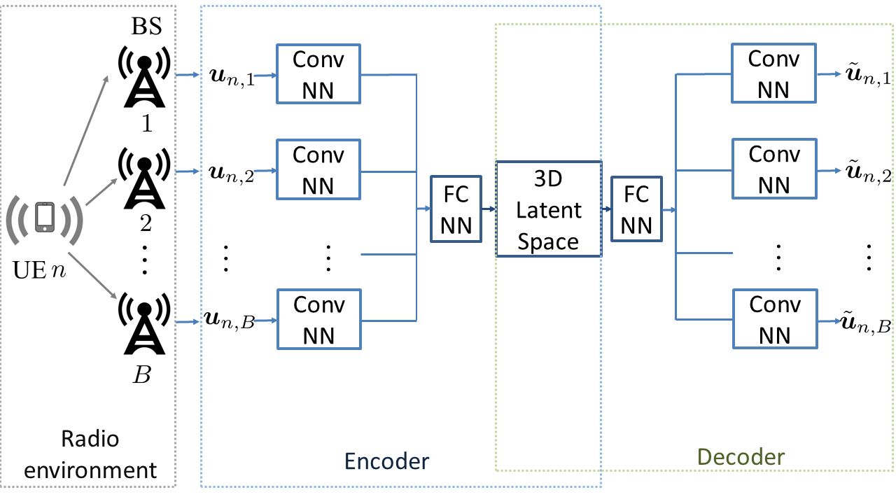
Fig. 1 presents the framework of CC mapping, in which each BS collects multipath information for each UE , and then, feeds the sample to a convolutional autoencoder. The autoencoder applies a convolutional neural network (CNN) based framework for unsupervised learning, which includes an encoder and a decoder. The encoder receives a high-dimensional CSI sample as its input, and implements a low-dimensional representation that captures the essential 3D location information of UE , where is the parameter of the encoder, and . Following that, a decoder with parameter is applied to reconstruct the CSI from the location representation for UE . The purpose of a decoder is to reconstruct CSI parameters that approximates the input sample, i.e., . To achieve this purpose and facilitate the performance evaluation of the autoencoder-based CC, the unlabeled CSI samples in are used for both the input and the training output.
As shown in Fig. 1, in the encoder part, the CSI sample is first processed by a local CNN at each BS to capture the local radio-geometry pattern. Then, all extracted information from different sources is fused together through a fully-connected neural network (FCNN) at a central learner, where the overall location properties of the considered equipment will be jointly evaluated, and finally the 3D code of the latent channel chart is extracted. Next, the decoder takes the location information in the CC space, learn the radio-geometry features near the considered equipment, and then, reconstruct the multipath parameters observed by BSs given the position of each BS. Consequently, the loss function of the overall CC framework given by:
| (5) |
where is the number of unlabeled CSI samples in for each BS, is the tuning parameter for the squared Frobenius regularizer, and is the FCNN parameter in the encoder. In the training phase, the Adam optimizer is used to minimize the loss function over and .
III-B Channel Charting-Aided Location Estimation
Given the unsupervised CC mapping, we will extend the autoencoder model to support a semi-supervised learning framework. Thus, labeled CSI samples whose 3D latent representation is given in can be employed to further improve the positioning accuracy of the CC-aided localization approach.
As mentioned before, the encoder itself can form a CNN-based positioning framework, where the input is the multipath channel sample , and the output is the estimated 3D location of UE . Meanwhile, the decoder can be considered as a channel predictor, where given the location as input, the multipath parameter can be generated as output at each BS . Therefore, using the labeled dataset , we can further train the encoder and decoder separately in a supervised manner. That is, after the CC training using the unlabeled dataset , we can divide the autoencoder model into an encoder and a decoder for UE localization and channel prediction, respectively, and each component can be optimized further using labeled CSI samples with associated location information.
In the supervised training of the encoder, we aim to estimate the location of the considered device given the multipath CSI, i.e., . Therefore, the loss function for the encoder-based localization task is
| (6) |
where is the number of labeled samples in for each BS. Then, in the training stage, parameter will be optimized to minimize the loss function for the encoder.
Meanwhile, the purpose of the decoder is to generate the multipath channel sample at each BS, given the known location of the considered device, i.e., . Thus, the approximate error for the decoder’s supervised learning is
| (7) |
Then, an optimization process will be applied to minimize over . To the best of our knowledge, this is the first work that applies a CC framework to assist semi-supervised localization, using a standalone autoencoder model. The training process for the proposed CC-aided localization approach is summarized in Algorithm 1.
IV Simulation Results and Analysis
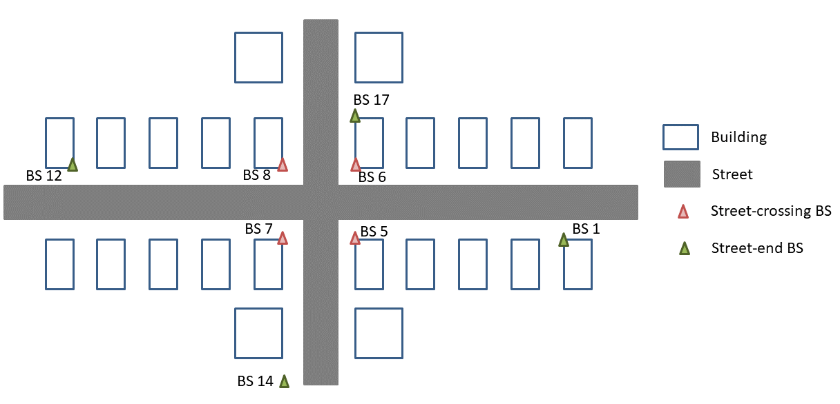
In our simulations, we consider BSs with antennas. Each UE is equipped with antennas. To evaluate the performance of the proposed CC-aided localization approach, we use the open-source DeepMIMO dataset in [17] that applies ray-tracing techniques to measure the AoA, AoD, ToA, phase, and power of channel gain for GHz communications in an outdoor street scenario with up to multipaths. We use labeled CSI samples, and unlabeled data. For both datasets, samples is employed for model training, and the remaining for testing. In our simulations, both LoS and NLoS channel states for mmWave MIMO communications are studied. As shown in Fig. 2, to support a LoS-dominant communication setting, we choose BSs , , , and , which are located near the crossing of two streets, to collect the CSI samples, where a LoS path exists for most of the mmWave links. For the NLoS-dominant scenario, we use BSs , , , and located at the end of each street to collect the channel parameters, thus most paths in the measured channels are reflected and NLoS.
For the autoencoder model, the encoder has four hidden layers, where the first three layers are convolutional with rectified linear unit (ReLU) activations, each of which is followed by a max-pooling operation, and the last hidden layer is fully-connected with a sigmoid activation. The decoder has a mirror structure of the encoder.
IV-A Performance of Channel Charting
To evaluate the accuracy of CC mapping, we consider two standard metrics, i.e., continuity (CT) and trustworthiness (TW), which are widely used for dimensionality reduction [7]. Both CT and TW have a value range within , and a larger value indicates a better CC mapping result. To define theses two metrics, first, we introduce as the set of -nearest neighbors of equipment in the real physical space, and we define as the ranking of device among the neighbors of based on their real-world 3D locations. In the CC latent space, we define to be the set of “false neighbors” that stay in the -nearest neighbors of in the latent space, but not of in the original location space. Meanwhile, is the ranking of device to device ranked by their latent locations in the channel chart. Then, CT is defined to measure on whether neighbors of each equipment in the real physical space are preserved in the latent charting space, i.e.,
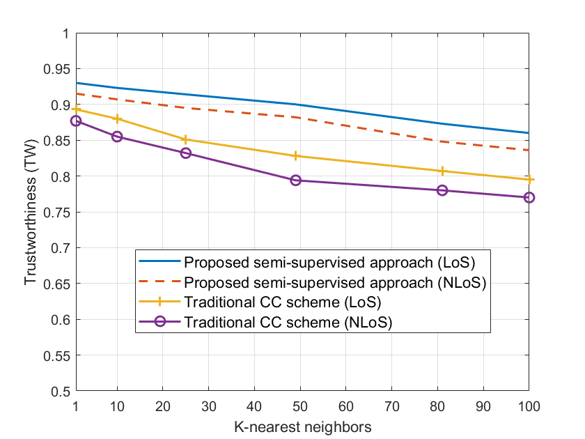
where a large CT value (close to ) means that all of the original neighbors of each UE remain close to it after CC mapping, thus, the latent space preserves the neighboring relationship of wireless UEs. Next, TW is defined to measure how well the CC mapping avoids introducing false neighbor relations that were absent in the original space, i.e.,
Here, a large TW value (close to ) indicates that no false neighbor is introduced after CC mapping.
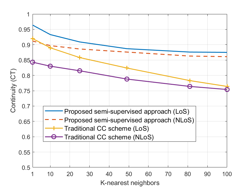
In Figs. 3 and 4, we compare the values of TW and CT, respectively, as the neighbor size increases from to . In order to evaluate the performance of our proposed semi-supervised approach, an unsupervised autoencoder is introduced as a baseline, which employs the same network topology in Fig. 1, but it does not access the labeled data in for model training. First, as shown in Fig. 3, our proposed CC method yields a larger CT value, compared with the baseline scheme, in both the LoS and NLoS communication scenarios. The proposed semi-supervised CC approach maps each device from the physical radio space to the 3D latent space while accurately preserving the neighboring relationship, such that most of the devices still have their original -nearest neighbors as their closest devices in the CC latent space. However, as the value of increases, the values of CT for both approaches decrease. As more neighbors are counted and compared between the original geometry space and the latent channel chart, it becomes more likely for an original neighbor to be mistakenly ranked lower after the CC mapping. Thus, the value of CT becomes smaller, given a larger neighbor size .
Compared with the baseline CC approach, the CT value of the proposed semi-supervised method decreases more slowly, for two reasons. First, the baseline CC only uses the unlabeled dataset to train the autoencoder, while our proposed approach can access two datasets and for more CSI samples. Given a larger size of training data, our proposed CC framework can capture an accurate pattern of CSI values associated with the location of each device. Thus, the spatial relationship can be better represented in the latent space, compared with the traditional CC algorithm. Next, the location information in the labeled dataset provides one more metric when determining the CSI similarity between multiple UEs. Therefore, the performance of semi-supervised learning is better and more robust, compared with the unsupervised CC model. For similar reasons, our proposed method also outperforms the baseline CC scheme, in the evaluation of TW value, as shown in Fig. 4. A larger TW value indicates that the proposed CC approach introduce less false neighbors to each UE in the latent CC space. In summary, compared with the traditional CC scheme that only applied unlabeled data for unsupervised learning, our proposed semi-supervised framework can improve the accuracy of CC mapping, using the location information in labeled CSI samples.
IV-B Performance of Localization
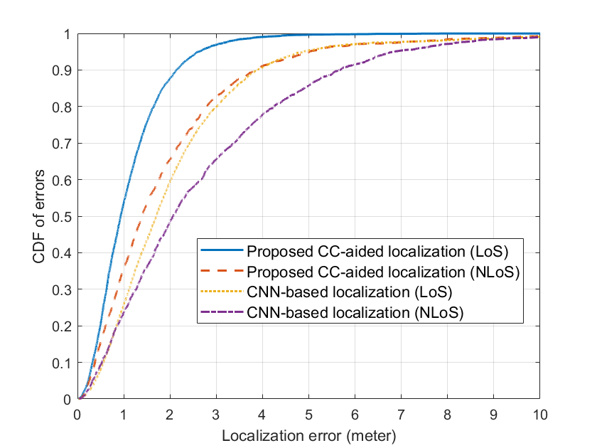
In Fig. 5, we evaluate the positioning accuracy of the proposed CC-aided localization method. For performance comparison, we introduce a baseline scheme that employs a CNN framework to predict the IoT device’s location based on CSI. The baseline model has the same structure as the encoder in Section III-B, which only applies the labeled dataset for model training, but it does not know any information about the channel chart. We use the norm- distance between the predicted location and real location as the performance metric.
Fig. 5 shows that our proposed CC-aided method outperforms the baseline scheme. First, in the LoS communication scenario, to achieve a localization error that is smaller than meters, our proposed positioning approach shows an empirical probability of over , while the baseline scheme only reaches . When the mmWave paths are dominated by NLoS links, the positioning accuracy of both approaches decreases, because an NLoS path cannot directly provide the angular information of the IoT device’s orientation. However, the CC mapping can capture the neighboring relationship between different wireless devices, such that the BSs can jointly learn the propagation features of surrounding environment based on multi-source CSI. Thus, the CC-aided localization scheme can obtain the reflection information of mmWave links to adjust the NLoS parameters, and then, infer the IoT’s position. Due to the aid of CC, our proposed semi-supervised localization scheme yields a smaller positioning error in both the LoS and NLoS communication scenarios, compared with a conventional supervised learning baseline.
V Conclusion
In this paper, we have proposed a novel framework for semi-supervised localization in a mmWave network. In particular, we have developed a convolutional autoencoder model to enable a CC-aided positioning using both labeled and unlabeled CSI dataset. In order to capture the radio-geometry map of the mmWave system, we have built a channel chart in an unsupervised manner. Next, we have divided the autoencoder model into two components, each of which was trained individually, using the labeled CSI dataset with associated location information, to further improve the positioning accuracy. Simulation results show that the proposed semi-supervised learning approach captures a better radio-geometry map than an unsupervised CC scheme. Meanwhile, our proposed CC-aided localization method yields a higher positioning accuracy, compared with a conventional supervised learning scheme.
References
- [1] A. Shahmansoori, G. E. Garcia, G. Destino, G. Seco-Granados, and H. Wymeersch, “Position and orientation estimation through millimeter-wave MIMO in 5G systems,” IEEE Transactions on Wireless Communications, vol. 17, no. 3, pp. 1822–1835, Mar 2018.
- [2] J. Xiao, K. Wu, Y. Yi, L. Wang, and L. M. Ni, “Pilot: Passive device-free indoor localization using channel state information,” in Proc. of IEEE International Conference on Distributed Computing Systems, Philadelphia, PA, USA, Jul 2013, pp. 236–245.
- [3] M. Zhou, Y. Tang, W. Nie, L. Xie, and X. Yang, “GrassMA: graph-based semi-supervised manifold alignment for indoor WLAN localization,” IEEE Sensors Journal, vol. 17, no. 21, pp. 7086–7095, Sep 2017.
- [4] A. Olivier, G. Bielsa, I. Tejado, M. Zorzi, J. Widmer, and P. Casari, “Lightweight indoor localization for 60-ghz millimeter wave systems,” in 2016 13th Annual IEEE International Conference on Sensing, Communication, and Networking, London, UK, Jun 2016, pp. 1–9.
- [5] J. Palacios, P. Casari, and J. Widmer, “JADE: Zero-knowledge device localization and environment mapping for millimeter wave systems,” in Proc. of IEEE Conference on Computer Communications, Atlanta, GA, USA, May 2017, pp. 1–9.
- [6] J. Chen, D. Steinmetzer, J. Classen, E. Knightly, and M. Hollick, “Pseudo lateration: Millimeter-wave localization using a single RF chain,” in Proc. of IEEE Wireless Communications and Networking Conference, San Francisco, CA, USA, Mar 2017, pp. 1–6.
- [7] C. Studer, S. Medjkouh, E. Gonultaş, T. Goldstein, and O. Tirkkonen, “Channel charting: Locating users within the radio environment using channel state information,” IEEE Access, vol. 6, pp. 47 682–47 698, Aug 2018.
- [8] C. Geng, H. Huang, and J. Langerman, “Multipoint channel charting with multiple-input multiple-output convolutional autoencoder,” in Proc. of IEEE/ION Position, Location and Navigation Symposium, Portland, Oregon, USA, Apr 2020, pp. 1022–1028.
- [9] J. Deng, S. Medjkouh, N. Malm, O. Tirkkonen, and C. Studer, “Multipoint channel charting for wireless networks,” in Proc. of IEEE Asilomar Conference on Signals, Systems, and Computers, Pacific Grove, CA, USA, Oct 2018, pp. 286–290.
- [10] J. J. Pan, S. J. Pan, J. Yin, L. M. Ni, and Q. Yang, “Tracking mobile users in wireless networks via semi-supervised colocalization,” IEEE Transactions on Pattern Analysis and Machine Intelligence, vol. 34, no. 3, pp. 587–600, Aug 2011.
- [11] B. Chidlovskii and L. Antsfeld, “Semi-supervised variational autoencoder for WiFi indoor localization,” in Proc. of IEEE International Conference on Indoor Positioning and Indoor Navigation, Pisa, Italy, Sep 2019, pp. 1–8.
- [12] Z. Abu-Shaban, X. Zhou, T. Abhayapala, G. Seco-Granados, and H. Wymeersch, “Error bounds for uplink and downlink 3D localization in 5G millimeter wave systems,” IEEE Transactions on Wireless Communications, vol. 17, no. 8, pp. 4939–4954, May 2018.
- [13] J. Song, J. Choi, T. Kim, and D. J. Love, “Advanced quantizer designs for FDD-based FD-MIMO systems using uniform planar arrays,” IEEE Transactions on Signal Processing, vol. 66, no. 14, pp. 3891–3905, May 2018.
- [14] Q. Zhang, A. Ferdowsi, W. Saad, and M. Bennis, “Distributed conditional generative adversarial networks (GANs) for data-driven millimeter wave communications in UAV networks,” arXiv preprint arXiv:2102.01751, 2021.
- [15] S. Wielandt and L. D. Strycker, “Indoor multipath assisted angle of arrival localization,” Sensors, vol. 17, no. 11, p. 2522, Nov 2017.
- [16] Y. Han and J. Lee, “Two-stage compressed sensing for millimeter wave channel estimation,” in Proc. of IEEE International Symposium on Information Theory, Barcelona, Spain, Jul 2016, pp. 860–864.
- [17] A. Alkhateeb, “DeepMIMO: A generic deep learning dataset for millimeter wave and massive MIMO applications,” arXiv preprint arXiv:1902.06435, 2019.