Pressure induced Lifshitz transition and anomalous crystal field splitting in AFeAs (A=Li/Na) Fe-based superconducting compounds: A first principles study
Abstract
Abstract: The effect of hydrostatic pressure on the electronic structures of iron pnictide superconducting compounds LiFeAs and NaFeAs through density functional theory based first principles studies are presented, using the predicted crystal structures at very high pressure by Zhang et al. Zhang et al. (2012). The orbital selective pressure induced modifications in the partial density of states and electronic band structures reveal mixed multi-band multi-orbital nature of these compounds, with energetically degenerate / orbitals at ambient pressure. Due to larger hydrostatic pressures some of the electron/hole bands crosses the Fermi level, leading to significant topological modifications in Fermi surfaces known as Lifshitz transition. Interrelation between Lifshitz transition and superconductivity-an important subject matter of current research are described. Based on such interconnection the current study predicts the superconducting- in 111 compounds can not be raised at such high pressures. Wannier functions based electronic structure investigation reveal a relatively larger hybridization between the Fe- and As- orbitals at higher pressures, as an effect of which the orbital degeneracy of and orbitals are lifted. Different hybridization contributions in the crystal-field splitting are separated using the Wannier functions based formalism, by incorporating different bands with a particular orbital character in the Wannier function construction. Pressure dependence of the intra/inter orbital hopping amplitudes between Fe- orbitals has been discussed using low energy tight binding model.
Keywords: Iron pnictides superconducting materials, Electronic structure calculations, Orbital characters, Lifshitz transition, Wannier functions, Crystal field splitting, Hopping parameters.
I Introduction
Microscopic origin of superconductivity in iron-based compounds (FeSCs) is still a mystery even after fourteen years of its discovery Kamihara et al. (2008). One of the very important facts about FeSCs is the occurrence of Lifshitz like topological transition (LT). LT occurs at absolute zero temperature in which Fermi surface topology of metallic compounds change abruptly Ghosh et al. (2021a, 2020); Ghosh and Ghosh (2019). No spontaneous symmetry breaking is involved in LT. LT is also observed in different condensed matter systems like \ceBi_2Sr_2CaCu_2O_8+δ cuprate superconductor Benhabib et al. (2015), 3D Dirac semi-metal \ceNa_3Bi Xu et al. (2015), bilayer graphene Lemonik et al. (2010), quantum hall liquids Varlet et al. (2014) etc. FeSCs are multiple-band superconductors with specific orbital characters. Although typically FeSCs have multiple electron as well as hole like Fermi surfaces, but there are a number of materials which probably do not exhibit the hole Fermi surfaces. For example, \ceBa_1-xK_xFe_2As_2 near Xu et al. (2013), \ceLiFe_1-xCo_xAs for Miao et al. (2015), K-dosed FeSe thin films Wen et al. (2016); Lei et al. (2016), FeSe single layer grown on \ceSrTiO_3 (FeSe/STO) substrate Liu et al. (2012), the intercalated compound (LiFe)OHFeSe Niu et al. (2015) etc. Due to multi band nature of electronic structure at the vicinity of the Fermi Level, it would be possible to tune the movement of any one or more number bands downward or upward depending on which high symmetry points in momentum space it crosses the Fermi Level through various external perturbations such as doping Xu et al. (2013), pressure Gupta et al. (2018) or even magnetic field Ptok et al. (2017) causing Lifshitz transitions. In literature there exists a reasonably well established inter-connection between the LT and the highest superconducting critical transition temperature (). For example, in \ceBa_1-xK_xFe_2As_2, the concurrence of highest K at and an electronic topological transition occurs at the same doping concentration Ghosh and Sen (2017); Xu et al. (2013); similarly in \ceBaFe_2-xCo_xAs_2, a common doping value of for the occurrence of K and LT Liu et al. (2011); in \ceBaFe2(As_1-xP_x)_2, the occurrence of K at and LT at Iye et al. (2012); in \ceCa_0.82La_0.18Fe_1-xNi_xAs_2, K at and LT occurs at same doping concentration Ghosh et al. (2019a)-are clear indications of existing interconnection between LT and . So, FeSCs have become proto-type systems where probability of Lifshitz transition and its connection with superconductivity need to be studied. High pressure is one of the most versatile parameter which can tune as well as electronic properties of the system Sen and Guo (2020); Ghosh and Ghosh (2021), though the study of pressure induced LT is rare. In this work we bring out the situation of pressure induced LT and its implication on superconductivity for two FeSC compounds LiFeAs and NaFeAs.
In general for high critical temperature superconductors, it is an well established fact that the pressure is a crucial controlling parameter of superconducting- and FeSCs are no exception of that Quader and Widom (2014). For example, in case of superconducting compound -\ceFe_1.01Se, transition temperature is increased from 8.5 K to 36 K under the application of 8.9 GPa pressure Medvedev et al. (2009). One more example is \ceBaFe_2As_2, a parent FeSC which posses a spin-density-wave (SDW) ground state with no superconducting properties but hydrostatic/chemical pressure (by means of doping in any of the three atomic sites) can induce superconductivity with a 30 K Mani et al. (2009). LiFeAs was the first discovered superconducting compound, belonging to 111 family with 18 K Tapp et al. (2008). The parent LiFeAs structure crystallizes in tetragonal symmetry with space group-, undergoes an structural phase transition under the application of hydrostatic pressure, as predicted by the theoretical study Zhang et al. (2012). It follows a structural transition sequence as predicted by the CALYPSO structure prediction method Zhang et al. (2012) under the application of 40 GPa, 60 GPa and 240 GPa pressure respectively. NaFeAs, another parent member of 111 family, shows superconductivity around 9 K, crystallize in primitive tetragonal structure with space group Parker et al. (2009). The critical transition temperature of \ceNa_1-xFeAs poly-crystalline sample can be enhanced up to 31 K as the pressure increases from ambient pressure to 3 GPa Zhang et al. (2009). In case of hole doped \ceNaFe_1-xCo_xAs (with x = 0.075) an enhancement of by 13 K is achieved under a pressure of 2.3 GPa Wang et al. (2012). According to the theoretical study Zhang et al. (2012), under external pressure (hydrostatic) NaFeAs show following structural transition in sequence . However, in the current literature the high pressure electronic structure and its implications on superconductivity are still missing. In this work, we provide a detailed systematic evolution of the electronic structures including crystal filed splitting with external pressure up to 240 GPa.
Crystal field splitting (CFS) is defined as the energy difference between the highest and the lowest orbital energy levels in the electron cloud of a transition metal element. Initially, the electrostatic potential of the surrounded ions was considered as the major source of CFS energy. But sooner, it became clear that hybridization between different orbitals of transition metal ions with the surrounded ligands must be considered for an accurate description of CFS Sugano and Shulman (1963). Other factors affecting the CFS energy are, (i) symmetry and coordination environment of the transition metal ion, (ii) the valance state of the cation, (iii) pressure and temperature. Under perfect tetrahedral crystal field at ambient pressure, the five fold degenerate -orbitals split into the triply degenerate levels and doubly degenerate levels. All the different family members of the FeSCs, share the similar Fe-As layer with tetrahedral symmetry at ambient pressure. Due to the effect of hybridization between the Fe -orbitals and the pnictogen/chalcogen- orbitals both the and orbitals further split, leaving only degenerate and orbitals de’ Medici (2014). Hydrostatic pressure can further modify this degree of hybridization, hence the corresponding crystal field splitting. Therefore, we have employed the maximally localized Wannier function (MLWF) formalism to analyze the effect of hybridization due to applied pressure on crystal field splitting Scaramucci et al. (2015); Xu et al. (2019).
From the above discussions, it is clear that both the electronic structure and CFS can be affected significantly by the application of hydrostatic pressure. In this article, we present a systematic study of both the properties using Density functional theory (DFT) based first principles method. In Sec. II we will discuss about the detail computational methodologies. Sec. III is subdivided into five parts, effect of pressure on: (III.1) orbital projected electronic band structure (BS) and Fermi surfaces, (III.2) orbital projected partial density of state (PDOS), (III.3) crystal field splitting in Wannier function formalism, (III.4/III.5) low energy tight binding models. Finally in Sec. IV, we summarize the main conclusions of this work.
II Computational details
The DFT-based electronic structure calculations are performed using the plane wave pseudo-potential based Quantum ESPRESSO code Giannozzi et al. (2017). The electronic exchange correlation is considered within the generalized gradient approximation (GGA) with Perdew-Burke-Enzerhof (PBE) functional Perdew et al. (1996). Here we have used experimental lattice parameters of LiFeAs and NaFeAs at atmospheric pressure Tapp et al. (2008); Parker et al. (2009) for the non spin polarized single point energy calculations. Zhang et al. theoretically determines the crystal structures of 111-FeSC materials at high pressures, based on particle-swarm optimization algorithm Zhang et al. (2012). These structural details are used as inputs in our calculations for electronic structure at high pressures. The plane wave cut-off energy for self consistent field (SCF) calculations are taken appropriately, after performing a rigorous convergence test. Monkhorst-Pack scheme has been used to sample the Brillouin zone (BZ) in k-space Monkhorst and Pack (1976); Pack and Monkhorst (1977). We have employed the WANNIER90 package Pizzi et al. (2020) to simulate low energy tight binding model and crystal field splitting. We use VETSA software package Momma and Izumi (2011) for visualization of Wannier functions and XCRYSDEN package Kokalj (2003) for the visualization of Fermi surfaces. Throughout the article the Fermi energy level is set to zero eV.
III Results and Discussions
III.1 Effect of pressure on Electronic band structure, Fermi surfaces and occurrence of Lifshitz like electronic topological transitions
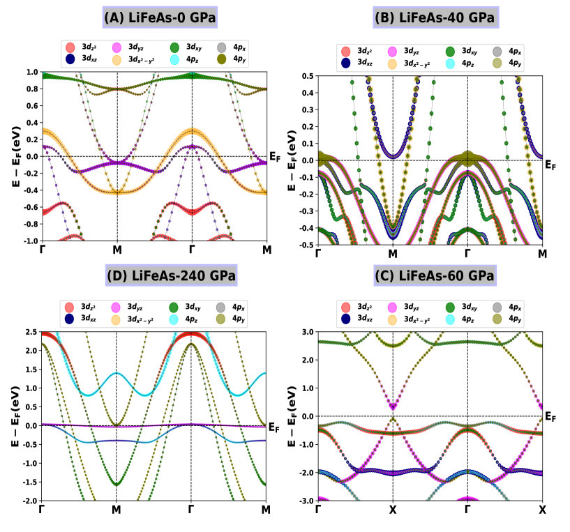
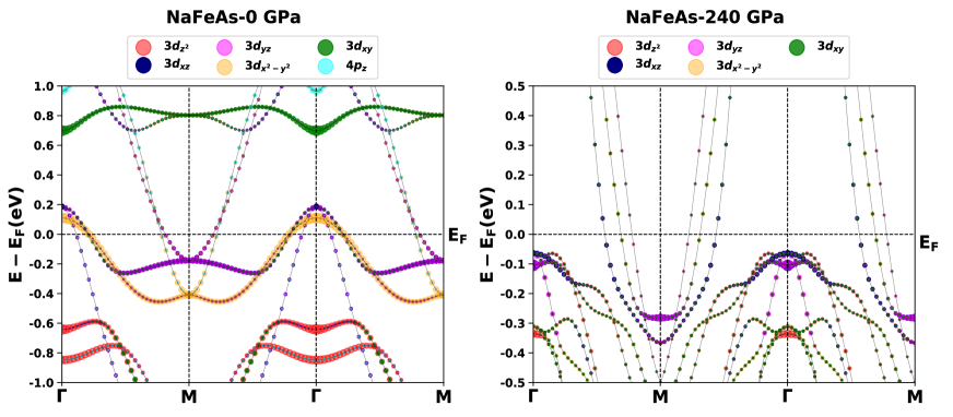
LiFeAs crystallizes in tetragonal crystal structure with space group Tapp et al. (2008). It shows structural transitions under the application of the hydrostatic pressure Zhang et al. (2012). It possesses trigonal, tetragonal and hexagonal crystal structures at 40 GPa, 60 GPa and 240 GPa pressure respectively. The orbital projected electronic band structures (OPBS) of LiFeAs at four different pressures are presented in Fig. 1, around the high symmetry points. The different orbital contributions are denoted by assigning a color to each orbital involved in the band formation. The orbital weight to the bands is proportional to the size of the circles. Red, blue, pink, yellow, green, cyan, gray, and olive colors are assigned to signify the , , , , , , , and orbitals, respectively. We have followed this same color scheme throughout this work. We have projected different atomic orbitals onto Kohn-Sham states to calculate the orbital character of different bands. OPBS reveal mixed multi-orbital multi-band nature in all the four different crystallographic symmetries studied here. At atmospheric pressure LiFeAs posses two electron like bands around M point and three hole like bands around \ceΓ point Borisenko et al. (2010) near Fermi level (see Fig-1A). Out of the three hole like bands around \ceΓ point, one band crosses the Fermi level (FL), having orbital character while other two bands lie just above the FL are almost degenerate, having mostly mixed , orbital character. There are two electron like bands that crosses the FL, of which one lies close to the FL and the other one is away from the FL. The band close to the FL is orbital derived and the band away from the FL is primarily of Fe , As orbital character. When pressure increases to 40 GPa, there is a drastic change in the electronic band structure that modifies to two hole like bands around \ceΓ point and two electron like bands around M point (see Fig-1B). Change in the orbital characters of the bands are also noteworthy. Two hole like bands are almost degenerate near the FL, one having As , orbital character while the other is As , orbital derived. Whereas both the electron like bands lie away from the FL, one having , orbital characters while the other has mixed , , , As character. It is worthwhile pointing out that both the hole like bands near point and the orbital derived electron like band at M point are on the verge of LT. A large number of hole like bands have already crossed the FL at and M points, such a behaviour is equivalent to large electron doping. At 60 GPa, LiFeAs experiences a metal-semiconductor transition where both the valance bands and conduction bands have multi-orbital nature (see Fig-1C). Valance bands near the FL at \ceΓ point have mixed , and As character. Conduction bands as well as valance bands at X point have mixed multi-orbital character comprising of , and As . In case of 240 GPa pressure, we observe five hole like bands at \ceΓ point and one electron like band at M point (see Fig-1D). Among the five hole like bands two of them lie very close to the FL and other three lie away from the FL. These two lower lying bands are almost degenerate and mostly have mixed , , As orbital character. Among three upper lying bands two are almost degenerate and mostly of As derived, while the third one is primarily orbital derived. The only electron like that band lies near FL is mostly derived from Fe orbital (see Fig-2). Therefore, larger presence of As- orbital character bands near the FL suggest that, at relatively higher pressure the mixing between Fe- and As- orbital increases. Another most important observation is, degeneracy of and orbitals at ambient pressure is lifted due to applied hydrostatic pressure.
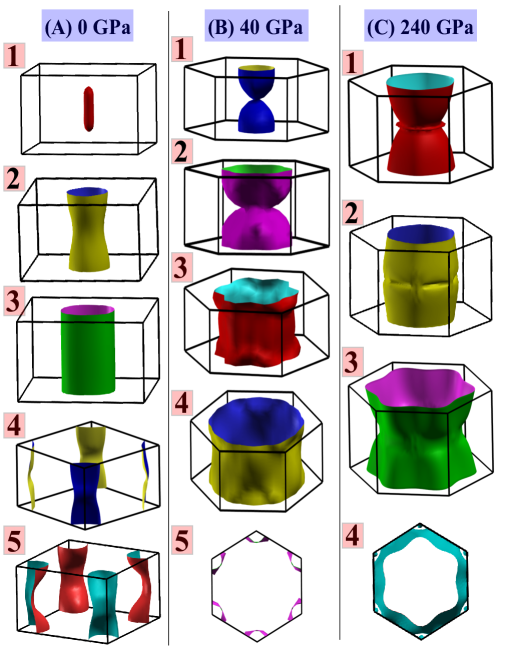
In case of iron based FeSC compounds the discussions regarding topology of Fermi surface (FS) is very much important. It may reveal various crucial information like possibility of Lifshitz like topological transitions, nesting condition etc. Ghosh et al. (2019b). Here, we will discuss about the evolution of FSs in LiFeAs compound at various pressures. At ambient pressure (Fig. 3A) there are three hole like FSs at the Brillouin zone centre (around -point) whereas there are two electron like FSs at the Brillouin zone corner (around -point). At 40 GPa pressure (Fig. 3B) there are four hole like FSs at the Brillouin zone centre and only one electron like FS at the Brillouin zone corner. Similar kind of hole/electron like FSs are found in first hexagonal Brillouin zone of hexagonal \ceMgB_2 Bekaert et al. (2017)/other 2D-metallic compounds Ouisse et al. (2015) respectively. At 240 GPa pressure (Fig. 3C) there are three hole like FS at the Brillouin zone centre and only one electron like FS at the Brillouin zone corner. Interestingly, the electron like FS has a very different character, consisting of rings connected by bridges and topologically parallel to the outside faces of the Brillouin zone. Similar kind of FSs are found in hexagonal FeS polymorph Parker (2017). So, hydrostatic pressure influences modification in topology of both the hole and electron like FSs. At ambient pressure at -point the hole FSs look like concentric cylinders, but with increasing pressure the radius of cylinder increases as well as slightly distorted in their shape. So, the nesting between hole like FS and electron like FS may be possible. This indicates enhanced possibility of repulsive inter band pairing interaction between hole and electron like FSs which may be advantageous for symmetry of the superconducting gap Ghosh et al. (2020). As the inner electron pockets are on the verge of LT, it is also possible that the nesting between hole and electron pockets are relatively weak. In Fig. 3 hole FS area increases with pressure whereas electron FSs undergo missing is an example of pressure induced LT. Here, our discussion about the nesting is qualitative only, explicit calculation of spin susceptibility/nesting function is required to comment on nesting property rigorously and quantitatively Graser et al. (2009).
Fermi surfaces of NaFeAs and occurrence of Lifshitz transition
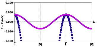
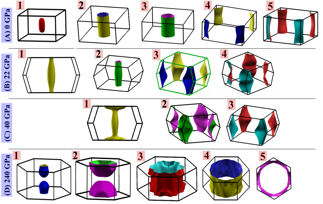
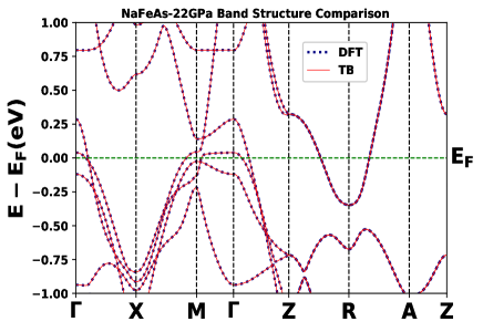
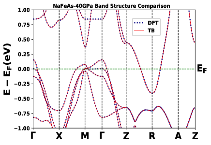
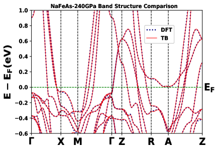
At ambient pressure NaFeAs also crystallizes in tetragonal crystal structure Parker et al. (2009). When hydrostatic pressure is applied, it shows several structural transitions Zhang et al. (2012). It possesses orthorhombic crystal structure upto pressures 40 GPa, then transformed to trigonal crystal structure. FS topology of NaFeAs at various pressures is shown in Fig. 4. At ambient pressure (Fig. 4A) there are three hole like FS at the Brillouin zone centre (around -point) whereas there are two electron like FS at the Brillouin zone corner (around -point). At 22 GPa pressure (Fig. 4B) there are two hole like FSs at the Brillouin zone centre and two electron like FSs at the Brillouin zone corner. At 40 GPa pressure (Fig. 4C) there are only one hole like FS at the Brillouin zone centre and two electron like FSs at the Brillouin zone corner. So, the shape and size of hole like FS are changing drastically with the applied pressure. Similar kind of hole like FSs are found in first hexagonal Brillouin zone of anti-ferromagnetic \ceBaFe_2As_2 Wang et al. (2015). At 240 GPa pressure (Fig. 4D) the innermost hole like FS segregates into two parts leading to Lifshitz transition. The same can be inferred from electronic band structure at Fig. 5. The hole like bands at -point gradually shifts below the FL with applied pressure. Topological modifications with appearance or destruction of new FS are the primary signatures of LT. Thus it is an example of hydrostatic pressure induced LT in NaFeAs. Again LT restricts superconducting Xu et al. (2013); Gupta et al. (2018), hence it could not be raised further with increasing pressure due to occurrence of LT.
III.2 Pressure dependent electronic structure of LiFeAs and NaFeAs
Orbital projected PDOS of LiFeAs
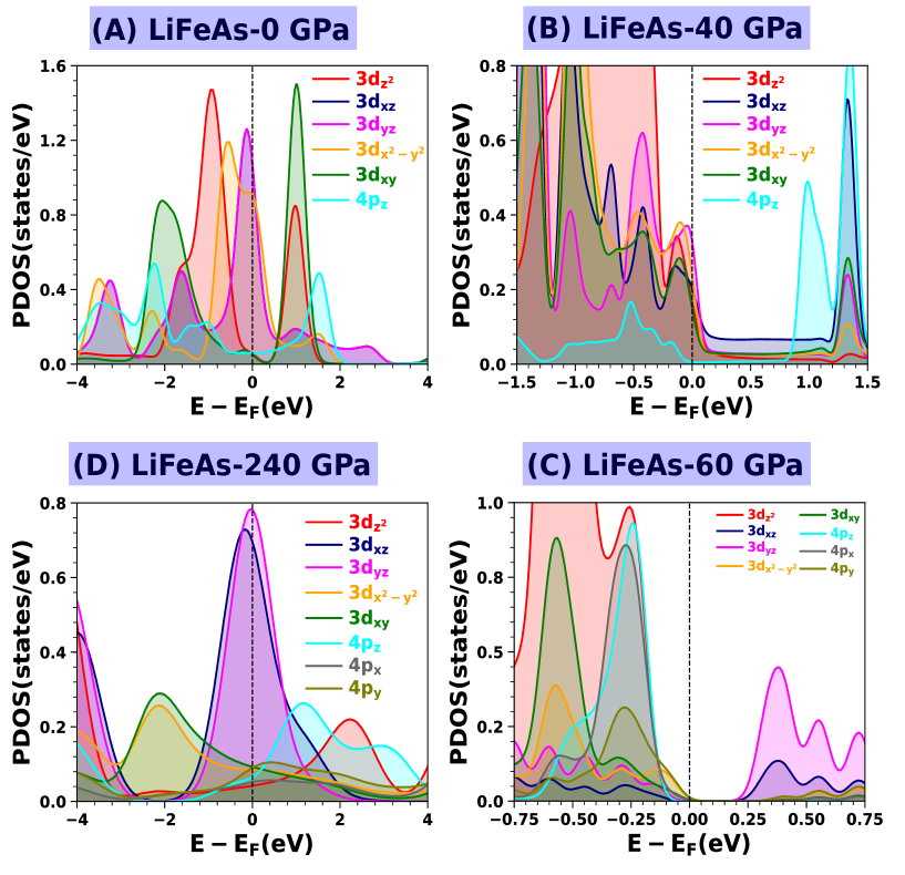
In Fig. 6 partial density of states of Fe- and As- orbitals for LiFeAs at different pressures are presented. The maximum contribution in the PDOS around the FL arises from the Fe- orbitals except at 60 GPa pressure, where As- orbitals also have significant contribution in the valance states. In case of LiFeAs, at atmospheric pressure the maximum contribution to the PDOS at FL arises from the and orbitals, out of five Fe- orbitals (see Fig. 6A). At atmospheric pressure the and orbitals contribute equally in the PDOS, hence they are degenerate in nature. The contributions of , and As orbitals to the PDOS at FL are the lowest. At 40 GPa pressure, maximum contributions to the PDOS at FL also arises from the and orbitals (see Fig. 6B). Here the contributions from , , orbitals are slightly less compared to other -orbitals, while As orbital contribution is almost zero. Most importantly, at 40 GPa pressure we notice different and orbital contributions to the PDOS at FL. At 60 GPa pressure, a band gap of around 0.16 eV near FL opens up which splits the bands into valance and conduction bands (see Fig. 6C). At valance band, maximum contributions to the PDOS arises from the , As- and As- orbitals. However, at conduction band and orbitals contribute the most in the PDOS. Here we observe and orbital contributions are also dissimilar. At 240 GPa pressure, maximum contribution to the PDOS at FL arises from the and orbitals (see Fig. 6D). In contrast, , and As orbitals contribute less but almost equally to the PDOS near FL. Here we also found a less but non zero contribution from the As and orbitals. Therefore, discussions on the overall nature of PDOS near the FL signals to the fact that individual Fe- and As- orbitals are affected differently due to the applied pressure. The above mentioned behavior of the and orbital PDOS demonstrate that, at relatively higher pressure they become non-degenerate.
Orbital projected PDOS of NaFeAs
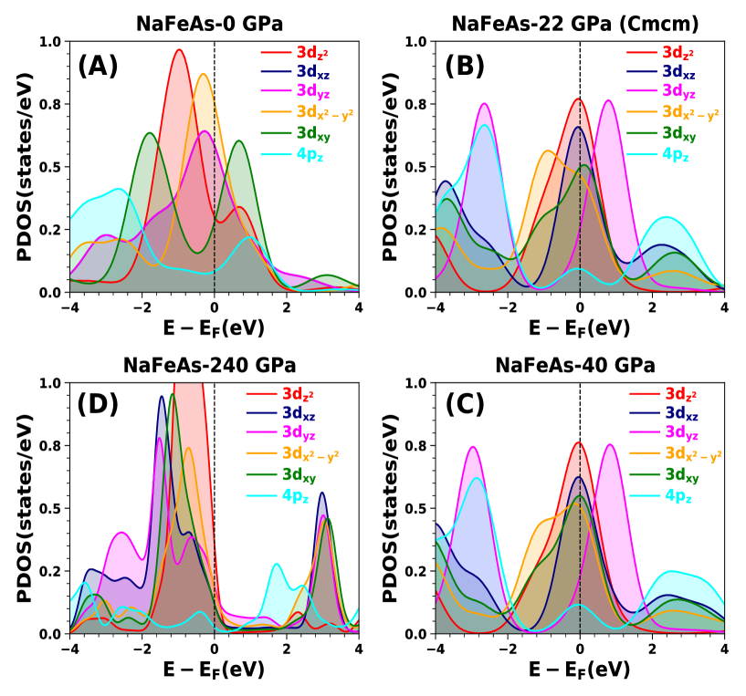
Orbital projected PDOS of Fe- and As- orbitals at different pressures are presented in Fig. 7. In all the cases the maximum contributions to the PDOS near the FL are coming from Fe -orbitals. At ambient pressure maximum contributions to the PDOS at FL arises from and orbitals (see Fig. 7A); whereas and orbital contributions are equal, but larger as compared to As orbitals. From Fig. 7A it is clear that and orbitals are degenerate at ambient pressure. This orbital degeneracy is lifted when hydrostatic pressure is applied (see Fig. 7B). Here the maximum contributions to the PDOS at FL arises from and orbitals. The contributions from and orbitals are almost equal, but less as compared to orbitals. Here we also find less but non-zero contributions of and As orbitals. At 40 GPa, and orbital PDOS at FL slightly decreases, while and orbital PDOS increases (see Fig. 7C). Here we also observe slight decrease in PDOS of orbitals, whereas an increase in As- orbital PDOS. At 240 GPa, largest contribution in PDOS near FL arises from Fe orbitals. The contribution from other orbitals in decreasing order can be viewed as , , , (see Fig. 7D). Here As orbital contribution is negligible. Therefore, the outcome of above discussions is that, overall nature of Fe- and As- orbitals PDOS near FL are affected differently due to the applied pressure. PDOS at FL reduces at 240 GPa pressure, this in turn reduce the possibility of electron pairing at higher pressure, which may result in decreasing superconducting . The observed nature of and orbitals PDOS in both the compounds (LiFeAs and NaFeAs) indicates that, at relatively higher pressure they may become non-degenerate. The same can be inferred from the electronic band structures. To physically interpret this degeneracy lifting mechanism, we have performed crystal field splitting calculation using Wannier function based formalism (Sec-III.3).
III.3 Anomalous crystal field splitting
In the presented electronic structure calculation (section-A/B) we have considered the Bloch states as the basis of the single particle electronic Hamiltonian. Bloch states in the periodic solids are characterized by a band index and a wave vector in the first Brillouin zone (FBZ). The many body Hamiltonian is diagonal in this basis Scaramucci et al. (2015):
| (1) |
Here, is the particle creation operator in the Bloch state , is the particle destruction operator and is the single particle energy of the corresponding state. The Bloch states are transformed into a set of atomic like Wannier functions (WFs) using a unitary transformation defined as Marzari et al. (2012):
| (2) |
The Wannier functions are characterized by a unit cell index along with an additional index which discriminate different Wannier orbitals in the same unit cell. The dependent unitary matrix mixes various Bloch functions at the same point to generate the WFs. But the Wannier functions generated using eq. (2) are non-unique, because different sets of leads to the different sets of Wannier orbitals. To overcome these difficulties, the Maximally localized Wannier functions (MLWF) technique is the most suitable way to define a unique set of Wannier functions Marzari and Vanderbilt (1997). The corresponding many body Hamiltonian becomes non-diagonal in this basis:
| (3) |
and the corresponding matrix element can be written as:
| (4) |
In case of iron based superconducting compounds, at atmospheric pressure each MLWF is located on a specific atomic sites (Wannier centers) and has a clear orbital character. This allows us to interpret MLWFs as effective tight binding (TB) orbitals Eschrig and Koepernik (2009); Ghosh et al. (2020); Miyake et al. (2010); Ghosh et al. (2021b). If either or the indices and corresponds to Wannier orbitals and at different atomic sites and , the matrix element in eq. (4) can be interpreted as the hopping amplitude between and , usually denoted as . If and corresponds to same site index and same orbital index in the same unit cell , then the corresponding matrix element is called onsite energies (). In this TB basis the onsite energy differences between different orbitals with predominant orbital character (e.g., Fe- or As-) can be comprehended as crystal field splitting.
Different sets of bands, with a predominant orbital characters are used to construct different sets of Wannier functions (depending on which bands are included in the summation of eq. (2)). Using this feature we can construct three different sets of Wannier functions (TB models) corresponding to : (i) ‘d-model’-only effective Fe- orbitals, (ii) ‘dp-model’ containing Fe- orbitals and As- orbitals, and (iii) ‘dps-model’ containing Fe- orbitals, As- orbitals, Li/Na- orbitals. The onsite energy difference, obtained using different orbital projections, can be interpreted as decomposition of the total crystal field splitting Scaramucci et al. (2015).
Crystal field splitting of LiFeAs under pressure
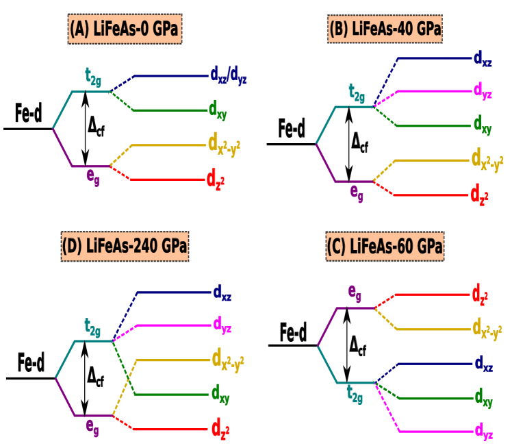
However, from Fig. 1 it can be seen that bands with predominant Fe- and As- orbital characters have major contributions in the electronic band structure near the FL. We construct MLWF for each group of bands separately and the resulting MLWFs can be viewed as atomic orbitals arising from hybridization between Fe/As/Li atoms. The onsite energies for the Fe-centered Wannier functions corresponding to the set of Fe- orbitals are denoted as . The crystal field splitting using this so called ‘d-model’ for LiFeAs at different pressures are presented in Fig. 8. At atmospheric pressure, in tetrahedral coordination, Fe- orbitals splits into the and orbitals de’ Medici (2014). Here we found orbitals are lower in energy than that of the corresponding orbitals (see Fig. 8A). The and orbitals are also degenerate. At 40 GPa pressure, in octahedral coordination, orbitals splits into non-degenerate orbitals and orbitals splits into orbitals (see Fig. 8B). Most importantly and orbital degeneracy is lifted by the application of hydrostatic pressure. At 60 GPa pressure, in tetragonal pyramid coordination (space group-) we found reversal of the crystal fields as compared to the tetragonal coordination (space group-) at ambient pressure. Here at 60 GPa pressure orbitals are energetically higher as compared to the orbitals (see Fig. 8C). The same phenomena had been observed in case of a negative charge transfer system \ceCsAuCl_3 Scaramucci et al. (2015). This metal-semiconductor transition may lead to reversal of the hybridization contribution to the - splitting. With the -dominated bands energetically lower than the -dominated bands, the hybridization may be stronger for orbitals than orbitals Scaramucci et al. (2015). At 240 GPa pressure, in hexagonal structure we observe reversal of and orbitals as compared to CFS at ambient pressure (see Fig. 8D). Most important splittings between the and multiplets are tabulated in the Table-1. The intra-multiplet splittings are symmetry dependent and can change sign across different symmetries.
| Orbitals | Pressure | |||
| 0 GPa | 40 GPa | 60 GPa | 240 GPa | |
| } | 0.0 | 0.130 | 0.072 | 0.147 |
| } | 0.133 | 0.616 | -0.067 | 0.622 |
| } | 0.187 | 0.090 | -0.015 | -0.203 |
| } | 0.111 | 0.574 | -0.066 | 0.698 |
| Bands considred in Wannier function construction | Symbol () | in eV at pressure | ||
| 0 GPa | 40 GPa | 240 GPa | ||
| only effective Fe- | 0.331 | 0.831 | 0.610 | |
| } 0.195 | } 0.516 | } 0.435 | ||
| Fe- and As- | 0.136 | 0.315 | 0.175 | |
| } 0.002 | } 0.014 | } 0.05 | ||
| Fe-, As- and Li- | 0.134 | 0.301 | 0.125 | |
The effect of hybridization between Fe atoms with As ligands as well as purely electrostatic contribution to the crystal potential are included in the onsite energies. We denote onsite energies of Fe-centered Wannier functions by , where the superscript indicates that corresponding Wannier functions are obtained using effective Fe- orbitals only. Then the onsite energy difference between and like Wannier orbitals can be interpreted as the full crystal field splitting . Practically, is calculated using difference between the average on-site energy of the three orbitals and that of the two orbitals Scaramucci et al. (2015). Then we construct second set of Wannier functions, using Fe- and As- orbitals. We denote the onsite energies of this so called ‘dp-model’ by . Then we construct third set of Wannier functions using Fe-, As- and Li- orbitals and denote the onsite energies of this so called ‘dps-model’ by . The splittings on the onsite energies for these three sets are tabulated in Table-2 at atmospheric pressure (0 GPa) and high pressures (40 and 240 GPa). Full crystal field splittings in ‘d-model’ are 0.331 eV, 0.831 eV and 0.631 eV at 0 GPa, 40 GPa and 240 GPa pressure respectively. By a close look one can see that at atmospheric pressure splitting is reduced by 0.195 eV in the second set as compared to the first. This 0.195 eV reduction can be understood as, the contribution to the splitting stemming from hybridization of the central Fe- orbitals with -orbitals of surrounding As ligands. At 40 GPa and 240 GPa this reduction due to hybridization are 0.516 eV and 0.435 eV respectively (see Table-2). This increasing contribution of hybridization into full CFS may be responsible for the lifting of and orbital degeneracy. It can be seen that in the ‘dps-model’ (third set) energy splitting further reduces by 2 meV, 14 meV and 50 meV at 0 GPa, 40 GPa and 240 GPa pressures respectively as compared to the second set of Wannier orbitals. These contributions are relatively less in the full CFS and can be interpreted as an effect of hybridization. Therefore, we can conclude that by including such more and more number of bands in the Wannier function construction i.e., by removing the inter-site hybridization effect on different sets of orbitals full CFS can be converged to a value having purely electrostatic contribution.
In summary, full CFS of 0.331 eV in LiFeAs at ambient pressure contains a contribution of 0.195 eV from hybridization, about 2 meV from hybridization and the rest 0.134 eV (40%) is of purely electrostatic origin. At 40 GPa pressure, full CFS of 0.831 eV contains a contribution of 0.516 eV from hybridization, about 14 meV from hybridization and 0.301 eV (36%) is of electrostatic origin. At 240 GPa pressure, full CFS of 0.610 eV contains a contribution of 0.435 eV from hybridization, about 50 meV from hybridization and the remaining 0.125 eV (20%) is of electrostatic origin. This systematic decrease in purely electrostatic contribution in full CFS with increasing pressure, implies larger hybridization effect due to the applied pressure.
Crystal field splitting of NaFeAs under pressure
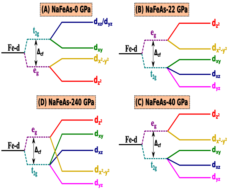
From Fig. 7 we find that Fe- and As- orbital contributes most in the partial density of states near FL. MLWFs are constructed for each group of bands separately and the resulting MLWFs can be viewed as atomic orbitals arising from hybridization between Fe/As/Na atoms. denote the onsite energies for the Fe-centered WFs corresponding to set of Fe- orbitals. The crystal field splitting using this so called ‘d-model’ for NaFeAs at different pressures are presented in Fig. 9. In tetrahedral coordination, at ambient pressure Fe- orbital splits into and orbitals de’ Medici (2014). Here, orbitals are non degenerate, but orbitals are degenerate (see Fig. 9A). Here we found orbitals are higher in energy than that of orbitals. At 22 GPa pressure, in distorted tetrahedral coordination Fe- orbital splits into doubly non degenerate orbitals and triply non degenerate orbitals (see Fig. 9B). Here we observed that hydrostatic pressure lifts the orbital degeneracy of orbitals completely. Again, this reverse the orbital orientation of and orbitals as compared to the tetrahedral coordination ( orbitals are energetically higher as compared to orbitals). In case of negative charge transfer system \ceCsAuCl_3, this similar kind of phenomena has been observed Scaramucci et al. (2015). At 40 GPa pressure there is no change in coordination environment of NaFeAs, hence CFS is least affected (see Fig. 9C). In octahedral coordination, at 240 GPa pressure orbitals penetrates in to orbitals (see Fig. 9D). Most important splittings between and multiplets are tabulated in the Table-3. The intra-multiplet splittings are symmetry dependent and can change sign across different symmetries.
| Orbitals | Pressure | |||
| 0 GPa | 22 GPa | 40 GPa | 240 GPa | |
| } | 0.0 | 0.076 | 0.093 | 0.135 |
| } | 0.080 | -0.167 | -0.263 | -0.152 |
| } | 0.320 | -0.042 | -0.001 | 0.033 |
| } | 0.014 | -0.003 | -0.029 | -0.060 |
| Bands considred in Wannier function construction | Symbol () | in eV at pressure | ||
| 0 GPa | 22 GPa | 40 GPa | ||
| only effective Fe- | 0.380 | 0.129 | 0.160 | |
| } 0.198 | } 0.114 | } 0.148 | ||
| Fe- and As- | 0.182 | 0.015 | 0.012 | |
| } 0.017 | } 0.007 | } 0.006 | ||
| Fe-, As- and Na- | 0.165 | 0.008 | 0.006 | |
Onsite energies include both the effects of hybridization between As/Fe atoms as well as pure electrostatic contribution to the crystal field potential. The onsite energies of Fe-centered Wannier functions are denoted by , where the superscript indicates that the corresponding WFs were obtained using effective Fe- orbitals as the initial projection. Then using Fe- and As- orbitals as initial projections, we construct second set of Wannier functions. Here we denote the onsite energies by and named it as ‘dp-model’. Then we construct a third set of Wannier functions using Fe-, As- and Na- as initial projections and denote the onsite energies by , we named it as ‘dps-model’. Different hybridization contributions on the onsite energies for these three sets are tabulated in Table-4 at ambient pressure (0 GPa) and at higher pressures (22 and 40 GPa). Full crystal field splitting measured in ‘d-model’ are 0.380 eV, 0.129 eV, and 0.160 eV at 0 GPa, 22 GPa, and 40 GPa pressures respectively. By a more closer look one can see that at ambient pressure splitting is reduced by 0.198 eV in the second set as compared to the first. This 0.198 eV reduction can be understood as the contribution to the splitting, stemming from hybridization of the central Fe- orbitals with -orbitals of surrounding As ligands. At 22 GPa and 40 GPa this reduction due to hybridization are 0.114 eV and 0.148 eV respectively. Hence, the contribution of hybridization into CFS increases from 52% to 88% with increasing pressure and increases further to 92.5% at 40 GPa. This increasing hybridization contribution into full CFS may be responsible for and orbital degeneracy lifting. It can be seen that in the third set (‘dps-model’) energy splitting further reduces by 17 meV, 8 meV, and 6 meV at 0 GPa, 22 GPa, and 40 GPa pressures respectively as compared to ‘dp-model’. In the full CFS these contributions are relatively less and can be interpreted as an effect of hybridization. Therefore, we can conclude that by removing the inter-site hybridization effect on different sets of orbitals i.e., including such more and more number of bands in the WF construction full CFS can be converged to a value having purely electrostatic contribution.
In summary, full CFS of 380 meV in NaFeAs at ambient pressure contains the contributions of 198 meV from hybridization, about 17 meV from hybridization and the rest 165 meV (43%) is of purely electrostatic origin. At 22 GPa pressure, full CFS of 129 meV contains the contributions of 114 meV from hybridization, about 8 meV from hybridization and 8 meV ( 6%) is of electrostatic origin. At 40 GPa pressure, full CFS of 160 meV contains the contributions of 148 meV from hybridization, about 6 meV from hybridization and remaining 6 meV ( 3.7%) is of electrostatic origin. This systematic decrease in purely electrostatic contribution in full CFS with increasing pressure, implies larger hybridization effect due to the applied pressure.
Visualization of Wannier functions
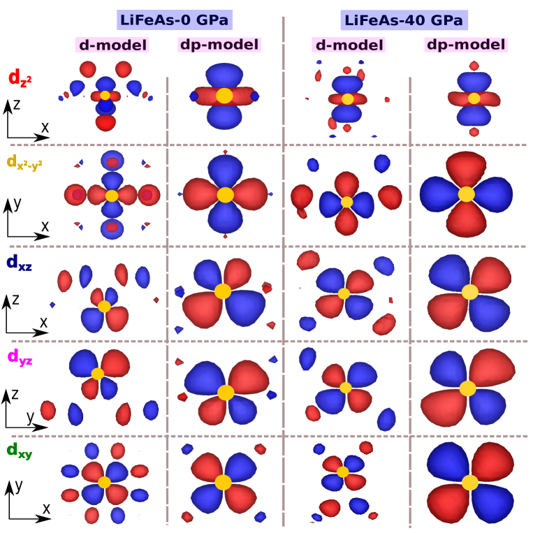
The resulting WFs for LiFeAs in the ‘d-model’ and ‘dp-model’ at ambient pressure and 40 GPa pressure are shown in Fig. 10. All the WFs are centered on Fe- sites. In ‘dp-model’ Fe- like WFs contain only minimal contributions for As- orbitals situated at the surrounding ligands. Overall, in ‘dp-model’ WFs are much more similar to the atomic orbitals as compared to the WFs of ‘d-model’.
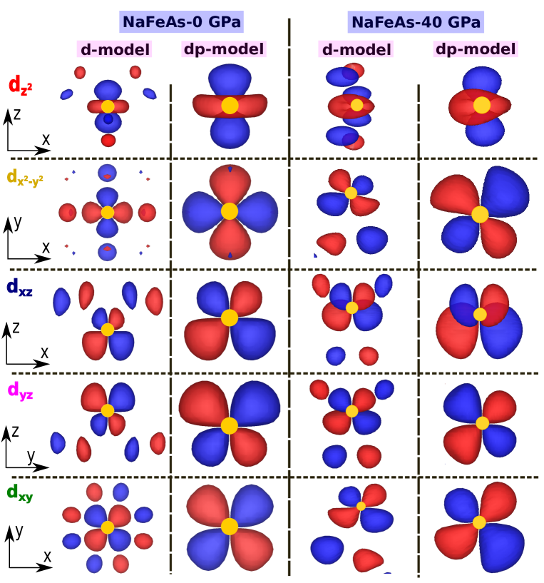
The resulting WFs for NaFeAs in the ‘d-model’ and ‘dp-model’ are shown in Fig. 11, at ambient pressure and 40 GPa pressure. Like LiFeAs, here all the WFs are centered on Fe- sites. In ‘dp-model’ Fe- like Wannier functions contain only minimal contributions from As- orbitals situated at the surrounding ligands. Overall, in the ‘dp-model’ WFs are much more similar to the atomic orbitals as compared to the Wannier functions of ‘d-model’, following the same trend as in LiFeAs. In the ‘dp-model’, at 40 GPa pressure WFs are more distorted as compared to that at ambient pressure due to the distorted tetrahedral coordination of the central Fe atom. We must note that, the chosen iso-surface value used for WF visualization decides the visible size of admixtures in Figs. 10, 11.
III.4 Low energy tight binding model of LiFeAs
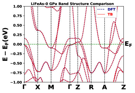
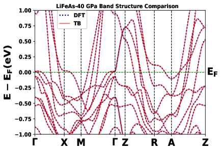
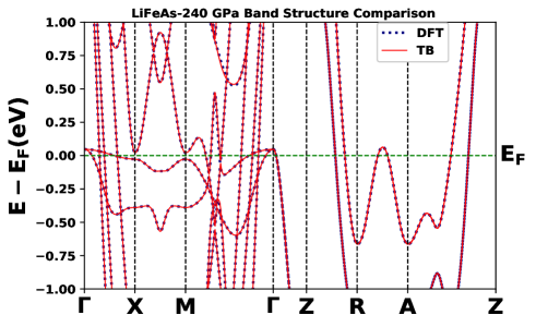
As we have mentioned earlier (section-III.3), the matrix elements in eq. (4) can be interpreted as the hoping amplitude between the two Wannier orbitals centered at different atomic sites. We obtain these hopping elements by constructing the maximally localized Wannier functions using effective Fe- orbitals in the finite energy window above and below the FL (-1.0 eV to 1.0 eV) except at 60 GPa pressure. At 60 GPa, we have considered both the Fe- and As- orbitals for the well converged MLWF construction. Effectively larger presence of As- orbitals PDOS (see Fig.-6C) at valance state may be responsible for this effect. The tight binding fitted band structures (red dashed curves) is compared with the DFT derived ones (blue continuous curves) in the Figs. 12-15 at different pressures. Here we obtain a perfect fitting for low energy bands in all the studied cases. We have presented the nearest-neighbours (NN) and the next-nearest-neighbours (NNN) intra as well as inter orbital hopping amplitudes in Table-5 for the different crystallographic symmetries. These hopping amplitudes are extracted from tight binding fitted band structures shown in the Figs. 12-15 and can be used to build effective low energy simplified model Hamiltonians.
| Pressure | orbitals | nearest-neighbours (NN) hopping amplitudes | next-nearest-neighbours (NNN) hopping amplitudes | ||||||||
| 0 GPa | -29.04 | 0.0 | -190.01 | 114.32 | 0.0 | -22.35 | -11.09 | 11.09 | 0.0 | -38.77 | |
| 0.0 | 125.88 | 0.0 | 0.0 | 151.40 | 11.09 | -3.14 | 0.0 | 2.0 | 2.59 | ||
| 190.01 | 0.0 | 385.03 | 88.77 | 0.0 | -11.09 | 0.0 | -3.14 | 2.0 | -2.59 | ||
| 114.32 | 0.0 | -88.77 | 131.01 | 0.0 | 0.0 | -2.00 | -2.00 | 2.19 | 0.0 | ||
| 0.0 | -151.40 | 0.0 | 0.0 | -60.67 | -38.77 | -2.59 | 2.59 | 0.0 | -38.42 | ||
| 40 GPa | -165.36 | 432.89 | 381.86 | 429.07 | 538.53 | -0.86 | -4.24 | 1.79 | 21.04 | -1.17 | |
| 36.69 | 258.05 | 179.41 | 83.94 | 187.82 | -0.61 | 0.41 | 2.39 | -0.62 | -1.31 | ||
| -39.37 | 159.86 | -0.44 | 162.73 | 59.14 | -1.49 | -0.44 | 1.37 | 3.85 | 0.51 | ||
| -38.71 | -0.51 | -33.94 | 2.48 | -8.62 | 1.08 | -0.12 | -0.58 | 0.32 | 0.18 | ||
| -62.77 | -46.44 | -6.96 | -13.64 | 36.35 | -0.56 | 2.08 | -1.01 | 1.11 | 0.68 | ||
| 60 GPa | 201.52 | 81.64 | -5.58 | 14.20 | -1.82 | 0.27 | -28.57 | 0.01 | 2.48 | -2.91 | |
| -76.64 | -219.09 | 44.23 | -53.50 | 44.75 | 36.74 | -12.41 | -0.08 | -36.60 | 10.36 | ||
| -5.13 | -44.38 | 954.84 | -252.08 | 1431.76 | 6.91 | 0.85 | -56.99 | 0.12 | -1.98 | ||
| -13.63 | -53.71 | 251.95 | -456.62 | 255.76 | -277.44 | -1086.84 | -1.42 | 386.08 | 207.24 | ||
| -1.37 | -44.70 | 1431.63 | -255.86 | 997.0 | -932.85 | -105.94 | -1.75 | -14.44 | 197.41 | ||
| 240 GPa | 88.82 | -41.50 | 21.20 | 207.92 | 106.82 | -23.36 | -39.23 | -168.31 | -50.37 | 215.81 | |
| 23.80 | 60.07 | -4.07 | -204.98 | 164.87 | -7.21 | 27.82 | -12.95 | 16.10 | -8.07 | ||
| -590.88 | 1296.80 | 320.87 | 449.46 | 11.36 | 52.21 | 51.04 | 37.28 | -7.35 | -302.78 | ||
| 58.22 | -93.91 | 14.73 | 520.71 | 36.27 | -17.78 | -20.40 | 16.02 | 25.96 | 9.90 | ||
| 193.38 | 67.89 | -8.50 | -334.54 | 448.27 | -4.61 | -0.63 | -26.10 | 3.71 | -43.45 | ||
From Table-5 it is evident that at atmospheric pressure NN intra-orbital hopping is maximum in the orbitals ( 385 meV), while inter-orbital hopping is maximum between the and orbitals ( 190 meV). In case of NNN interaction intra-orbital hopping is maximum in the orbitals (sign neglected) and inter-orbital hopping is maximum between the and orbitals ( 38.77 meV). At 40 GPa pressure NN intra-orbital hopping is maximum in the orbitals ( 258 meV), while inter-orbital hopping is maximum between the and orbitals ( 538 meV). In case of NNN interaction intra-orbital hopping amplitudes are very less as compared to the NN hopping amplitudes. At 60 GPa, NN intra-orbital hopping is maximum in the orbitals ( 997 meV), while inter-orbital hopping is maximum between the and orbitals ( 1431 meV). In case of NNN interaction intra-orbital hopping is maximum in the orbitals ( 386 meV) and inter-orbital hopping is maximum between the and orbitals (sign neglected). At very high pressure around 240 GPa, NN intra-orbital hopping is maximum in the orbitals ( 520 meV), while inter-orbital hopping is maximum between the and orbitals ( 1297 meV). In case of NNN interaction intra-orbital hopping is maximum in the orbitals and inter-orbital hopping is maximum between the and orbitals. Therefore, the main features observed in intra as well as inter-orbital hopping amplitudes may be summarized as-(i) at ambient pressure intra-orbital hopping amplitudes are dominant, while inter-orbital hopping amplitudes becomes predominant with the increasing pressure, (ii) intra-orbital as well as inter-orbital hopping amplitudes are maximum in the semi-conducting phase (at 60 GPa), (iii) in metallic phase intra/inter-orbital hopping amplitudes increases with the increasing pressure, (iv) hopping amplitudes are strongly dependent on crystallographic symmetry.
III.5 Low energy tight binding model of NaFeAs under pressure
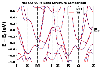
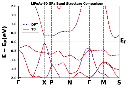
For NaFeAs, MLWFs constructed using effective Fe- orbitals as initial projections in the finite energy window above and below the FL (-1.0 eV to 1.0 eV) are used to obtain the hopping elements. DFT derived low energy band structures (blue dotted curves) are compared with the tight binding fitted ones (red dashed curve) in Figs. 16-19 at different pressures. In all the studied cases we find almost perfect fitting near the FL. We have presented the nearest-neighbours (NN) and next-nearest-neighbours (NNN) hopping amplitudes (intra as well as inter orbital) in Table-6 for the different crystallographic symmetries. These hopping amplitudes are extracted from the tight binding fitted band structures shown in Figs. 16-19.
| Pressure | Orbitals | Nearest-neighbours (NN) hopping amplitudes | Next-nearest-neighbours (NNN) hopping amplitudes | ||||||||
| 0 GPa | -25.55 | -4.40 | -154.53 | 112.88 | -0.27 | -8.07 | -16.95 | -0.40 | 12.95 | -5.72 | |
| 4.25 | 116.50 | 6.02 | 1.29 | 124.67 | -16.58 | -31.48 | 18.33 | 13.65 | 32.83 | ||
| 160.06 | 7.07 | 368.36 | 61.06 | -3.54 | -0.69 | 19.20 | 14.28 | 4.38 | -14.52 | ||
| 111.35 | -1.25 | -62.97 | 77.30 | -0.26 | 12.88 | 14.17 | 3.86 | 35.53 | -18.79 | ||
| 0.26 | -122.03 | 4.03 | 0.21 | -55.72 | -5.89 | 32.86 | 15.96 | -19.07 | 8.82 | ||
| 22 GPa | -43.53 | 229.56 | -148.38 | -217.34 | 68.34 | -48.75 | -94.83 | 260.30 | 53.83 | -224.39 | |
| 229.56 | 26.27 | 25.37 | 40.32 | -43.41 | -94.83 | -640.44 | 187.50 | 499.95 | 3.66 | ||
| -148.38 | 25.36 | -692.25 | 28.85 | 524.98 | 260.30 | 187.50 | -25.19 | -160.06 | 41.52 | ||
| -217.35 | 40.32 | 28.85 | -164.68 | 96.38 | 53.83 | 499.95 | -160.06 | -88.51 | 88.07 | ||
| 68.34 | -43.41 | 524.98 | 96.38 | -102.25 | -224.39 | 3.66 | 41.52 | 88.07 | -172.97 | ||
| 40 GPa | -52.75 | 239.70 | -169.14 | -250.89 | 7.93 | -52.93 | -78.82 | 283.63 | 6.26 | -251.30 | |
| 239.70 | 49.43 | 0.58 | 18.54 | -45.90 | -78.82 | -663.13 | 258.05 | 528.23 | 8.62 | ||
| -169.14 | 0.58 | -756.46 | 5.96 | 578.97 | 283.63 | 258.05 | -43.55 | -238.72 | 17.08 | ||
| -250.88 | 18.54 | 5.96 | -186.94 | 102.05 | 6.26 | 528.23 | -238.72 | -103.96 | 101.19 | ||
| 7.93 | -45.90 | 578.97 | 102.05 | -104.84 | -251.30 | 8.62 | 17.08 | 101.18 | -187.19 | ||
| 240 GPa | 148.40 | -3.14 | 132.12 | 659.91 | -6.25 | 140.68 | 209.68 | -112.94 | -302.82 | 496.37 | |
| 4.30 | 85.06 | 0.82 | 2.72 | -204.98 | 123.09 | -292.60 | 217.04 | -200.45 | 154.97 | ||
| 83.34 | -0.85 | -471.02 | 188.67 | -2.84 | -76.95 | 196.52 | -35.21 | -43.33 | -299.33 | ||
| 300.69 | 2.19 | 335.64 | -372.37 | 12.25 | -146.28 | -107.01 | 157.91 | -2.77 | 214.04 | ||
| -2.74 | 90.24 | -0.19 | 1.62 | 135.88 | 237.85 | 297.83 | -119.16 | 235.90 | -262.53 | ||
From Table-6 it is evident that at ambient pressure NN intra-orbital hopping is maximum in between the orbitals ( 368 meV), while inter-orbital hopping is maximum between and orbitals ( 160 meV). In case of NNN interaction intra-orbital hopping is maximum in the orbitals and inter-orbital hopping is maximum between and orbitals ( 32.86 meV). At 40 GPa, NN intra-orbital hopping is maximum in orbitals ( 692 meV, sign neglected), while inter-orbital hopping is maximum between and orbitals ( 525 meV). In case of NNN interaction intra-orbital hopping is maximum in between the orbitals ( 640 meV) and inter-orbital hopping is maximum between and orbitals. At 40 GPa pressure, NN intra-orbital hopping is maximum in between orbitals ( 756 meV, sign neglected), while inter-orbital hopping is maximum between and orbitals ( 579 meV). In case of NNN interaction intra-orbital hopping amplitudes are also comparable with NN hopping amplitudes. At relatively high pressure around 240 GPa, NN intra-orbital hopping is maximum in between orbitals ( 471 meV), while inter-orbital hopping is maximum between and orbitals ( 660 meV). In case of NNN interaction intra-orbital hopping is maximum in between orbitals and inter-orbital hopping is maximum between and orbitals.
Therefore, the observed features in intra as well as inter-orbitals hopping amplitudes can be summarized as-(i) at relatively lower pressure (upto 40 GPa) intra-orbital hopping amplitudes are larger, while inter-orbital hopping amplitudes becomes predominant at very high pressure, (ii) in metallic phase intra/inter-orbital hopping amplitudes increases with increasing pressure from 22 to 40 GPa, (iii) intra-orbital as well as inter-orbital hopping amplitudes are maximum at 40 GPa, (iv) hopping amplitudes are strongly crystallographic symmetry dependent, hence directly related to local structural environment of Fe atom along with its hybridization with surrounding As ligands. Local structural environment of Fe atom at various pressures can be understood from Fe -edge core electron spectroscopic study of Ref. Ghosh and Ghosh (2021).
IV Conclusions
We have presented detailed electronic structure study using DFT based first principles calculations for the iron based superconducting materials LiFeAs and NaFeAs under pressure, ranging from atmospheric pressure to very high pressures (up to 240 GPa). Orbital selective partial density of states of individual Fe- and As- orbitals near the Fermi level and their contributions in electronic band structures are affected differently due to applied pressure. At atmospheric pressure only Fe- orbitals contribute significantly in the resulting electronic structure. But at higher pressures relatively larger presence of As- orbital character bands near the FL suggest a larger overlap between Fe- and As- orbitals. Here we also recognize a metal-semiconductor transition in LiFeAs at 60 GPa pressure with band-gap around 0.16 eV, in accordance with the earlier studies Zhang et al. (2012). The inner electron FS are on the verge of Lifshitz transition in LiFeAs, so the nesting between hole and electron pockets are relatively weak. Occurrence of Lifshitz like topological transition for NaFeAs at 240 GPa pressure is visible. Most importantly, we found that at atmospheric pressure and -orbitals are degenerate in crystal field splitting, which is lifted by the application of hydrostatic pressure. Increasing hybridization between the Fe- orbitals with the surrounding As ligand’s orbitals at higher pressures may be responsible for this degeneracy lifting phenomena. We establish the above through estimation of hybridization contribution in the full crystal field splitting energy, using maximally localized Wannier functions based formalism. The purely electrostatic energy contribution into full crystal field splitting also decreases with the increasing pressure, i.e., favoring orbital overlap. For LiFeAs intra-orbital and inter-orbital nearest neighbour hopping amplitudes are maximum at the semiconducting state and for metallic state they increase with increasing pressure. In case of NaFeAs, the intra-orbital nearest neighbour hopping amplitudes are maximum at relatively lower pressure (upto 40 GPa), while the inter-orbital hopping amplitudes becomes predominant at very high pressure. We also contemplate that the nearest-neighbour hopping amplitudes are more than one order of magnitude larger as compared to next-nearest-neighbour hopping amplitudes. Furthermore, the so-obtained tight binding parameters can be used to build simplified model Hamiltonians. These in turn allow access to the temperature dependent properties that are not accessible through density functional theory formalism. Finally, we believe our study will stimulate more theoretical and experimental activities in this domain.
CRediT authorship contribution statement
The problem is formulated and conceptualized by H. Ghosh and S. Ghosh. All the theoretical calculations in the paper are carried out by S. Ghosh. The first draft of the manuscript was written by S. Ghosh and reformulated by H. Ghosh. Formal and critical analysis of the results were performed by both the authors.
Acknowledgements
SG thanks A. Ghosh and A. Pokhriyal for fruitful discussions. Authors acknowledge Computer Division, RRCAT for providing scientific computing facilities. Financial support for this work to SG is provided by the HBNI-RRCAT.
Author Declaration
The authors declare no conflict of interest.
Data Availability Statement
The data that support the findings of this study are available from the corresponding author upon reasonable request.
References
- Zhang et al. (2012) X. Zhang, Y. Wang, and Y. Ma, Phys. Chem. Chem. Phys. 14, 15029 (2012).
- Kamihara et al. (2008) Y. Kamihara, T. Watanabe, M. Hirano, and H. Hosono, Journal of the American Chemical Society 130, 3296 (2008).
- Ghosh et al. (2021a) A. Ghosh, S. Sen, and H. Ghosh, Computational Materials Science 186, 109991 (2021a).
- Ghosh et al. (2020) A. Ghosh, S. Ghosh, and H. Ghosh, Computational Materials Science 183, 109802 (2020).
- Ghosh and Ghosh (2019) A. Ghosh and H. Ghosh, Computational Materials Science 160, 62 (2019).
- Benhabib et al. (2015) S. Benhabib, A. Sacuto, M. Civelli, I. Paul, M. Cazayous, Y. Gallais, M.-A. Méasson, R. D. Zhong, J. Schneeloch, G. D. Gu, D. Colson, and A. Forget, Phys. Rev. Lett. 114, 147001 (2015).
- Xu et al. (2015) S.-Y. Xu, C. Liu, I. Belopolski, S. K. Kushwaha, R. Sankar, J. W. Krizan, T.-R. Chang, C. M. Polley, J. Adell, T. Balasubramanian, K. Miyamoto, N. Alidoust, G. Bian, M. Neupane, H.-T. Jeng, C.-Y. Huang, W.-F. Tsai, T. Okuda, A. Bansil, F. C. Chou, R. J. Cava, H. Lin, and M. Z. Hasan, Phys. Rev. B 92, 075115 (2015).
- Lemonik et al. (2010) Y. Lemonik, I. L. Aleiner, C. Toke, and V. I. Fal’ko, Phys. Rev. B 82, 201408 (2010).
- Varlet et al. (2014) A. Varlet, D. Bischoff, P. Simonet, K. Watanabe, T. Taniguchi, T. Ihn, K. Ensslin, M. Mucha-Kruczyński, and V. I. Fal’ko, Phys. Rev. Lett. 113, 116602 (2014).
- Xu et al. (2013) N. Xu, P. Richard, X. Shi, A. van Roekeghem, T. Qian, E. Razzoli, E. Rienks, G.-F. Chen, E. Ieki, K. Nakayama, T. Sato, T. Takahashi, M. Shi, and H. Ding, Phys. Rev. B 88, 220508 (2013).
- Miao et al. (2015) H. Miao, T. Qian, X. Shi, P. Richard, T. K. Kim, M. Hoesch, L. Y. Xing, X.-C. Wang, C.-Q. Jin, J.-P. Hu, and H. Ding, Nature Communications 6, 6056 (2015).
- Wen et al. (2016) C. H. P. Wen, H. C. Xu, C. Chen, Z. C. Huang, X. Lou, Y. J. Pu, Q. Song, B. P. Xie, M. Abdel-Hafiez, D. A. Chareev, A. N. Vasiliev, R. Peng, and D. L. Feng, Nature Communications 7, 10840 (2016).
- Lei et al. (2016) B. Lei, J. H. Cui, Z. J. Xiang, C. Shang, N. Z. Wang, G. J. Ye, X. G. Luo, T. Wu, Z. Sun, and X. H. Chen, Phys. Rev. Lett. 116, 077002 (2016).
- Liu et al. (2012) D. Liu, W. Zhang, D. Mou, J. He, Y.-B. Ou, Q.-Y. Wang, Z. Li, L. Wang, L. Zhao, S. He, Y. Peng, X. Liu, C. Chen, L. Yu, G. Liu, X. Dong, J. Zhang, C. Chen, Z. Xu, J. Hu, X. Chen, X. Ma, Q. Xue, and X. J. Zhou, Nature Communications 3, 931 (2012).
- Niu et al. (2015) X. H. Niu, R. Peng, H. C. Xu, Y. J. Yan, J. Jiang, D. F. Xu, T. L. Yu, Q. Song, Z. C. Huang, Y. X. Wang, B. P. Xie, X. F. Lu, N. Z. Wang, X. H. Chen, Z. Sun, and D. L. Feng, Phys. Rev. B 92, 060504 (2015).
- Gupta et al. (2018) S. N. Gupta, A. Singh, K. Pal, D. V. S. Muthu, C. Shekhar, M. A. Elghazali, P. G. Naumov, S. A. Medvedev, C. Felser, U. V. Waghmare, and A. K. Sood, Journal of Physics: Condensed Matter 30, 185401 (2018).
- Ptok et al. (2017) A. Ptok, K. J. Kapcia, A. Cichy, A. M. Oleś, and P. Piekarz, Scientific reports 7, 41979 (2017).
- Ghosh and Sen (2017) H. Ghosh and S. Sen, Journal of Physics and Chemistry of Solids 103, 170 (2017).
- Liu et al. (2011) C. Liu, A. D. Palczewski, R. S. Dhaka, T. Kondo, R. M. Fernandes, E. D. Mun, H. Hodovanets, A. N. Thaler, J. Schmalian, S. L. Bud’ko, P. C. Canfield, and A. Kaminski, Phys. Rev. B 84, 020509 (2011).
- Iye et al. (2012) T. Iye, Y. Nakai, S. Kitagawa, K. Ishida, S. Kasahara, T. Shibauchi, Y. Matsuda, and T. Terashima, Phys. Rev. B 85, 184505 (2012).
- Ghosh et al. (2019a) A. Ghosh, H. Ghosh, and S. Sen, Intermetallics 107, 126 (2019a).
- Sen and Guo (2020) S. Sen and G.-Y. Guo, Phys. Rev. Materials 4, 104802 (2020).
- Ghosh and Ghosh (2021) S. Ghosh and H. Ghosh, Computational Materials Science 192, 110316 (2021).
- Quader and Widom (2014) K. Quader and M. Widom, Phys. Rev. B 90, 144512 (2014).
- Medvedev et al. (2009) S. Medvedev, T. M. McQueen, I. A. Troyan, T. Palasyuk, M. I. Eremets, R. J. Cava, S. Naghavi, F. Casper, V. Ksenofontov, G. Wortmann, and C. Felser, Nature Materials 8, 630 (2009).
- Mani et al. (2009) A. Mani, N. Ghosh, S. Paulraj, A. Bharathi, and C. S. Sundar, Europhysics Letters 87, 17004 (2009).
- Tapp et al. (2008) J. H. Tapp, Z. Tang, B. Lv, K. Sasmal, B. Lorenz, P. C. W. Chu, and A. M. Guloy, Phys. Rev. B 78, 060505 (2008).
- Parker et al. (2009) D. R. Parker, M. J. Pitcher, P. J. Baker, I. Franke, T. Lancaster, S. J. Blundell, and S. J. Clarke, Chem. Commun. , 2189 (2009).
- Zhang et al. (2009) S. J. Zhang, X. C. Wang, Q. Q. Liu, Y. X. Lv, X. H. Yu, Z. J. Lin, Y. S. Zhao, L. Wang, Y. Ding, H. K. Mao, and C. Q. Jin, Europhysics Letters 88, 47008 (2009).
- Wang et al. (2012) A. F. Wang, Z. J. Xiang, J. J. Ying, Y. J. Yan, P. Cheng, G. J. Ye, X. G. Luo, and X. H. Chen, New Journal of Physics 14, 113043 (2012).
- Sugano and Shulman (1963) S. Sugano and R. G. Shulman, Phys. Rev. 130, 517 (1963).
- de’ Medici (2014) L. de’ Medici, Springer Series in Materials Science , 409–441 (2014).
- Scaramucci et al. (2015) A. Scaramucci, J. Ammann, N. A. Spaldin, and C. Ederer, Journal of Physics: Condensed Matter 27, 175503 (2015).
- Xu et al. (2019) C. Xu, Q. Chen, and C. Cao, Communications Physics 2, 16 (2019).
- Giannozzi et al. (2017) P. Giannozzi, O. Andreussi, T. Brumme, O. Bunau, M. B. Nardelli, M. Calandra, R. Car, C. Cavazzoni, D. Ceresoli, M. Cococcioni, N. Colonna, I. Carnimeo, A. D. Corso, S. de Gironcoli, P. Delugas, R. A. DiStasio, A. Ferretti, A. Floris, G. Fratesi, G. Fugallo, R. Gebauer, U. Gerstmann, F. Giustino, T. Gorni, J. Jia, M. Kawamura, H.-Y. Ko, A. Kokalj, E. Küçükbenli, M. Lazzeri, M. Marsili, N. Marzari, F. Mauri, N. L. Nguyen, H.-V. Nguyen, A. O. de-la Roza, L. Paulatto, S. Poncé, D. Rocca, R. Sabatini, B. Santra, M. Schlipf, A. P. Seitsonen, A. Smogunov, I. Timrov, T. Thonhauser, P. Umari, N. Vast, X. Wu, and S. Baroni, Journal of Physics: Condensed Matter 29, 465901 (2017).
- Perdew et al. (1996) J. P. Perdew, K. Burke, and M. Ernzerhof, Phys. Rev. Lett. 77, 3865 (1996).
- Monkhorst and Pack (1976) H. J. Monkhorst and J. D. Pack, Phys. Rev. B 13, 5188 (1976).
- Pack and Monkhorst (1977) J. D. Pack and H. J. Monkhorst, Phys. Rev. B 16, 1748 (1977).
- Pizzi et al. (2020) G. Pizzi, V. Vitale, R. Arita, S. Blügel, F. Freimuth, G. Géranton, M. Gibertini, D. Gresch, C. Johnson, T. Koretsune, J. Ibañez-Azpiroz, H. Lee, J.-M. Lihm, D. Marchand, A. Marrazzo, Y. Mokrousov, J. I. Mustafa, Y. Nohara, Y. Nomura, L. Paulatto, S. Poncé, T. Ponweiser, J. Qiao, F. Thöle, S. S. Tsirkin, M. Wierzbowska, N. Marzari, D. Vanderbilt, I. Souza, A. A. Mostofi, and J. R. Yates, Journal of Physics: Condensed Matter 32, 165902 (2020).
- Momma and Izumi (2011) K. Momma and F. Izumi, Journal of Applied Crystallography 44, 1272 (2011).
- Kokalj (2003) A. Kokalj, Computational Materials Science 28, 155 (2003), proceedings of the Symposium on Software Development for Process and Materials Design.
- Borisenko et al. (2010) S. V. Borisenko, V. B. Zabolotnyy, D. V. Evtushinsky, T. K. Kim, I. V. Morozov, A. N. Yaresko, A. A. Kordyuk, G. Behr, A. Vasiliev, R. Follath, and B. Büchner, Phys. Rev. Lett. 105, 067002 (2010).
- Ghosh et al. (2019b) A. Ghosh, H. Ghosh, and S. Sen, Intermetallics 107, 126 (2019b).
- Bekaert et al. (2017) J. Bekaert, L. Bignardi, A. Aperis, P. van Abswoude, C. Mattevi, S. Gorovikov, L. Petaccia, A. Goldoni, B. Partoens, P. M. Oppeneer, F. M. Peeters, M. V. Milošević, P. Rudolf, and C. Cepek, Scientific Reports 7, 14458 (2017).
- Ouisse et al. (2015) T. Ouisse, L. Shi, B. A. Piot, B. Hackens, V. Mauchamp, and D. Chaussende, Phys. Rev. B 92, 045133 (2015).
- Parker (2017) D. S. Parker, Scientific Reports 7, 3388 (2017).
- Graser et al. (2009) S. Graser, T. A. Maier, P. J. Hirschfeld, and D. J. Scalapino, New Journal of Physics 11, 025016 (2009).
- Wang et al. (2015) Y. Wang, M. N. Gastiasoro, B. M. Andersen, M. Tomić, H. O. Jeschke, R. Valentí, I. Paul, and P. J. Hirschfeld, Phys. Rev. Lett. 114, 097003 (2015).
- Marzari et al. (2012) N. Marzari, A. A. Mostofi, J. R. Yates, I. Souza, and D. Vanderbilt, Rev. Mod. Phys. 84, 1419 (2012).
- Marzari and Vanderbilt (1997) N. Marzari and D. Vanderbilt, Phys. Rev. B 56, 12847 (1997).
- Eschrig and Koepernik (2009) H. Eschrig and K. Koepernik, Phys. Rev. B 80, 104503 (2009).
- Miyake et al. (2010) T. Miyake, K. Nakamura, R. Arita, and M. Imada, Journal of the Physical Society of Japan 79, 044705 (2010).
- Ghosh et al. (2021b) A. Ghosh, S. Ghosh, and H. Ghosh, “Nematicity and crystal field splitting in newly discovered hybrid 12442 iron based superconductors,” (2021b), (manuscript under review).