Generation of High-Order Coarse Quad Meshes
on CAD Models via Integer Linear Programming
Abstract
We propose an end-to-end pipeline to robustly generate high-quality, high-order and coarse quadrilateral meshes on CAD models. This kind of mesh enables the use of high-order analysis techniques such as high-order finite element methods or isogeometric analysis. An initial unstructured mesh is generated; this mesh contains a low number of irregular vertices but these are not necessarily aligned, causing a very dense quad layout. A T-mesh is built on the mesh which allows to modify its topology by assigning new integer lengths to the T-mesh arcs. The task of simplifying the quad layout can be formulated as an Integer Linear Program which is solved efficiently using an adequate solver. Finally, a high-order quad mesh is extracted from the optimized topology. Validation on several CAD models shows that our approach is fast, robust, strictly respects the CAD features, and achieves interesting results in terms of coarseness and quality.
1 Introduction
Computer Aided Design (CAD) systems are used extensively for industrial design in many domains, including automotive, shipbuilding, aerospace industries, industrial and architectural design, prosthetics, and many more. Engineering designs are encapsulated in CAD models, which, up to manufacturing precision, exactly represent their geometry. While the engineering analysis process begins with such CAD models, the predominant method of analysis (the finite element method) requires an alternative, discrete, representation of the geometry: a finite element mesh. In a mesh, the CAD model is usually subdivided into a large collection of simple geometrical shapes. Mesh generation can thus be seen as the transmission belt between CAD and analysis. Notice that, even though the mesh is not geometrically as precise as the CAD, mesh data are usually way larger than CAD data.
The surface of a CAD model is typically defined by piecewise-smooth CAD patches. CAD models are filled with various idiosyncrasies: periodic surfaces, trimmed patches, exotic or singular parametrizations. The idea of this paper is to provide a representation of the CAD that is light, universal and precise. For that, we build a high-order quad layout of the whole CAD model. A quad layout is the partitioning of an object’s surface into simple networks of conforming quadrilateral patches. A high-order quad layout is a quad layout where individual patches are endowed with a geometry. Here, individual patches are both i) truly smooth and ii) share the same topology (four sides, no internal boundaries). The geometry of individual high order quad patches can be described either using high order finite elements or can inherit from the CAD representation (e.g. surface B-splines). The quad patches can be aligned with some of the feature edges of the CAD model but can also ignore some.
Such a coarse high-order quad layout can be used as a CAD model but also as a mesh in a high-order finite element context (-FEM), or in numerical techniques with NURBS-based representation of the geometry, such as isogeometric analysis [1] and NEFEM [2]. It can also be used a lightweight datastructure for forming an inline block-structured quad mesh. Block-structured meshes are of great interest for geometric multigrid or fast to design computation kernels.
In this paper we propose a practical approach to the generation of high-quality high-order quad layouts, where the emphasis is on robustness with respect to complex CAD models commonly occurring in engineering analysis. Our approach consists in first generating an unstructured linear and fine quadrilateral mesh, then modifying its topology until it is possible to extract a coarse quad layout.
Three-dimensional CAD models are represented on a computer using a Boundary Representation (BRep): a volume is bounded by a set of faces, a face is bounded by a series of curves and a curve is bounded by two end points. The BRep is a discrete object: it is a graph that contains model entities together with all their topological adjacencies. Then a geometry is associated to each model entity. Here, we aim at handling real life CAD models occurring in engineering analysis, which serve as a support for finite element or finite volume methods. Such models may be arbirtary complex, because of their size (large number of model entities) and/or because of the existence of sharp angles and features at very different scales. This complexity makes the robust treatment of CAD models particularly challenging.
In this work, we make the following assumption: the model is assumed to be a 2-manifold. Each model curve must be adjacent to at most two model faces. This limitation is due to implementation difficulties and could be overriden in a future work. At first let us define specifications for the high-order quad layout.
-
1.
The layout should be conforming, i.e., free of T-junctions. This is a necessary condition for most applications (multiblock meshing, isogeometric analysis).
-
2.
The quadrilaterals of the layout should strictly conform to the CAD, i.e., the quad corners should exactly lie on the underlying model surfaces and quad edges should strictly be aligned with a set of user-flagged model curves.
-
3.
The mesh should be valid and, to a certain extent, geometry-consistent; the exact meaning of these terms will be detailed later.
-
4.
The layout should be coarse; hence our primary concern is to minimize the number of quads in the layout.
The idea here is to start from a quad layout that does not fulfill all specifications and then to transform it to obtain compliance with the specifications. In our approach, the starting point is a valid quad mesh: a quad layout can be extracted from a conforming quad mesh and this layout verifies all expected specifications except the last one: a quad mesh does not usually produce a coarse layout (see §2 and Figure 2). This is mainly caused by non-alignment of the irregular vertices.
1.1 Related work
The generation of coarse quadrilateral layouts, also called base-complex in the literature, is a well-studied problem. For planar models and open surfaces, starting from a fine quad mesh, a simple approach is to iteratively collapse the chords (dual quad loops) which separate the irregular vertices that should be aligned. Unfortunately, this does not generalize to closed surfaces because the chords tend to wind up around the whole model, and collapsing them would simply destroy the mesh.
Bommes et al. [3] automatically detect helical configurations, i.e., quad loops forming helices winding around the model, and correct them by modifying the mesh directly using elementary operations (such as collapsing and shifting edges) that preserve the quad-nature of the mesh. But this approach is not sufficient to deal with many other configurations, such as self-intersecting quad loops.
Tarini et al. [4] extract the quad layout from the input mesh and simplify it by iteratively changing connections between irregular vertices in a greedy fashion, in order to minimize concurrently the separatrices’ length and drift (how much they deviate from the underlying cross field). Once the new separatrices are optimized, the mesh is re-parametrized to align it with the new layout.
Razafindrazaka et al. [5] optimize the network of separatrices connecting irregular vertices by formulating it as a graph matching. The resulting network is optimal with respect to a user-specified balance between coarseness and geometric feature alignment.
An alternative approach is to directly produce the coarse quadrilateral layout from a seamless parametrization (consistent global integration of a cross-field). Lyon et al. [6] first build a T-mesh (non-conforming quad layout with T-junctions) from a seamless global -parametrization. The integer lengths of the T-edges are then optimized to achieve a conforming coarse layout. The benefit of this approach is that it encodes an infinite number of layout connections in a finite structure, and allows to flexibly impose constraints.
These papers have in common that they focus on computer graphics applications, where CAD consistency is generally not a concern and where the number of feature curves is limited. Our work aims at achieving similar results but with the additional constraint that the quad layout must comply with a complex CAD model.
1.2 Overview
For the construction of the coarse layout, we build on the recent quantization simplification of Lyon et al. [6] as it provides the most flexibility to impose the constraints related to CAD compliance. Besides additional CAD constraints, the main difference with their work is that we use only quadrilateral meshes: neither a global seamless parametrization nor a cross field is needed here. In a CAD context, we believe that starting from an unstructured quad mesh is more robust as it is much easier to generate one compared to a valid global seamless parametrization.
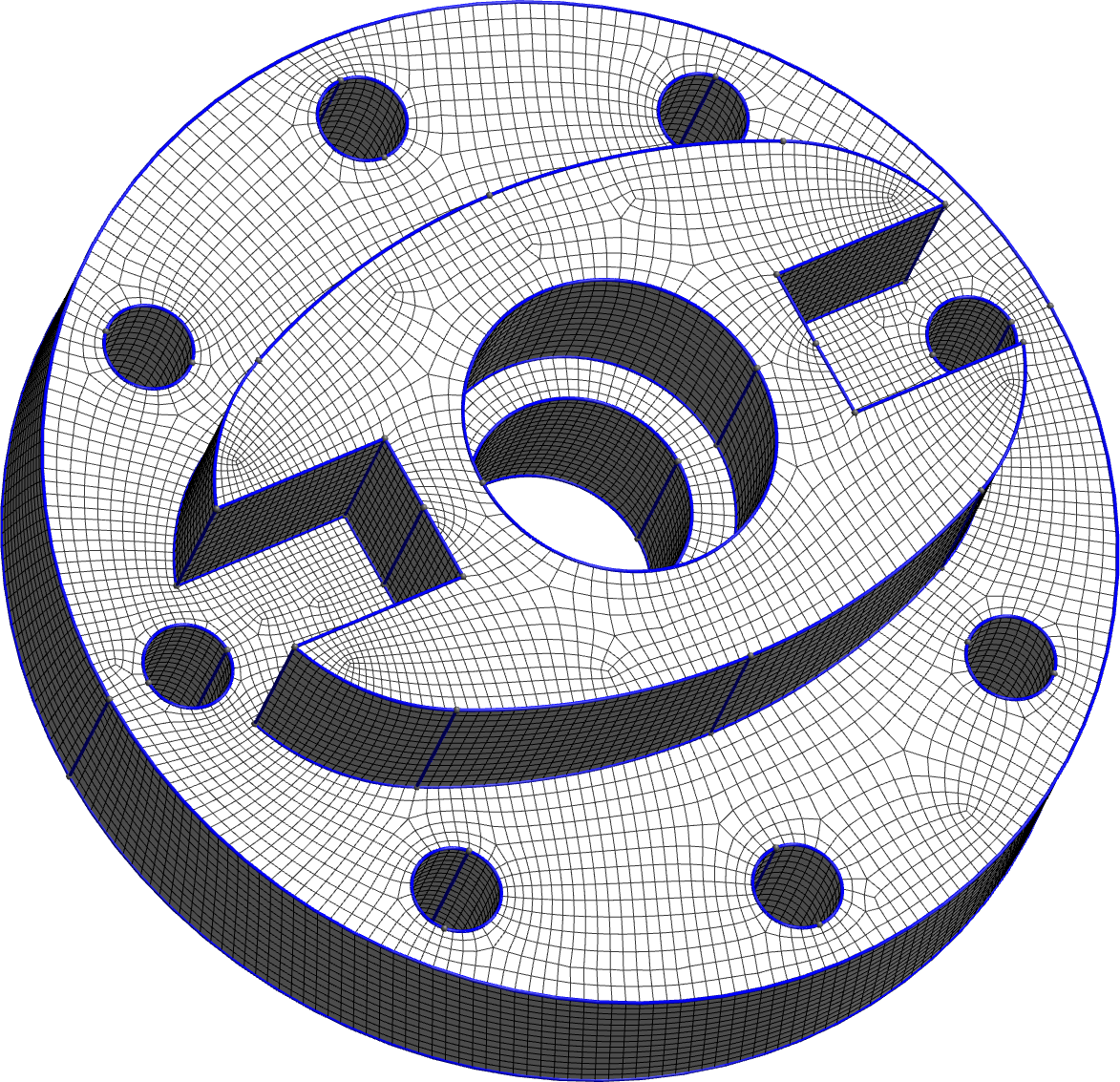
Our complete method for building a high-order quadrilateral layout from a CAD model works as follows, and is illustrated in Figure 1:

2 Quasi-structured quadrilateral meshing
The first step of our pipeline is to obtain a high-quality unstructured quadrilateral mesh from the given CAD model. A mesh vertex is regular if its valence (number of incident faces) is equal to 4; otherwise it is irregular. A quad mesh is said to be quasi-structured if it has few irregular vertices compared to meshes produced with usual unstructured techniques. Our group has recently proposed a robust end-to-end pipeline to achieve this task [7], which is freely available in the open-source software Gmsh [9]. The idea is to use a boundary-aligned smooth cross field to guide the point insertion in a frontal mesher, then to improve the quad mesh topology by remeshing large convex cavities while respecting the cross field singularities. This method forms the first step of our pipeline and is used to generate the initial unstructured quad mesh.
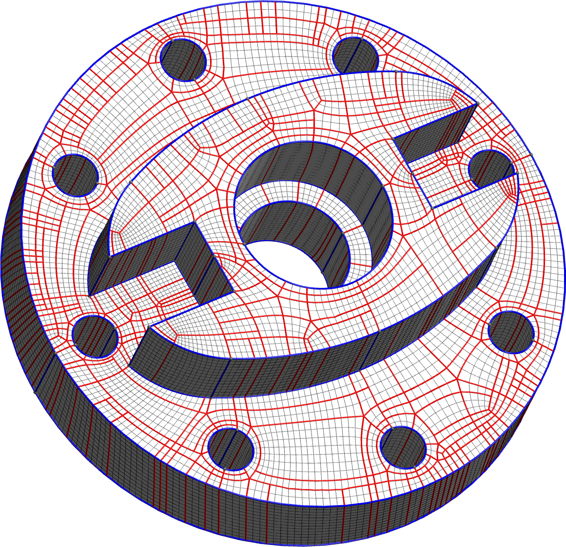
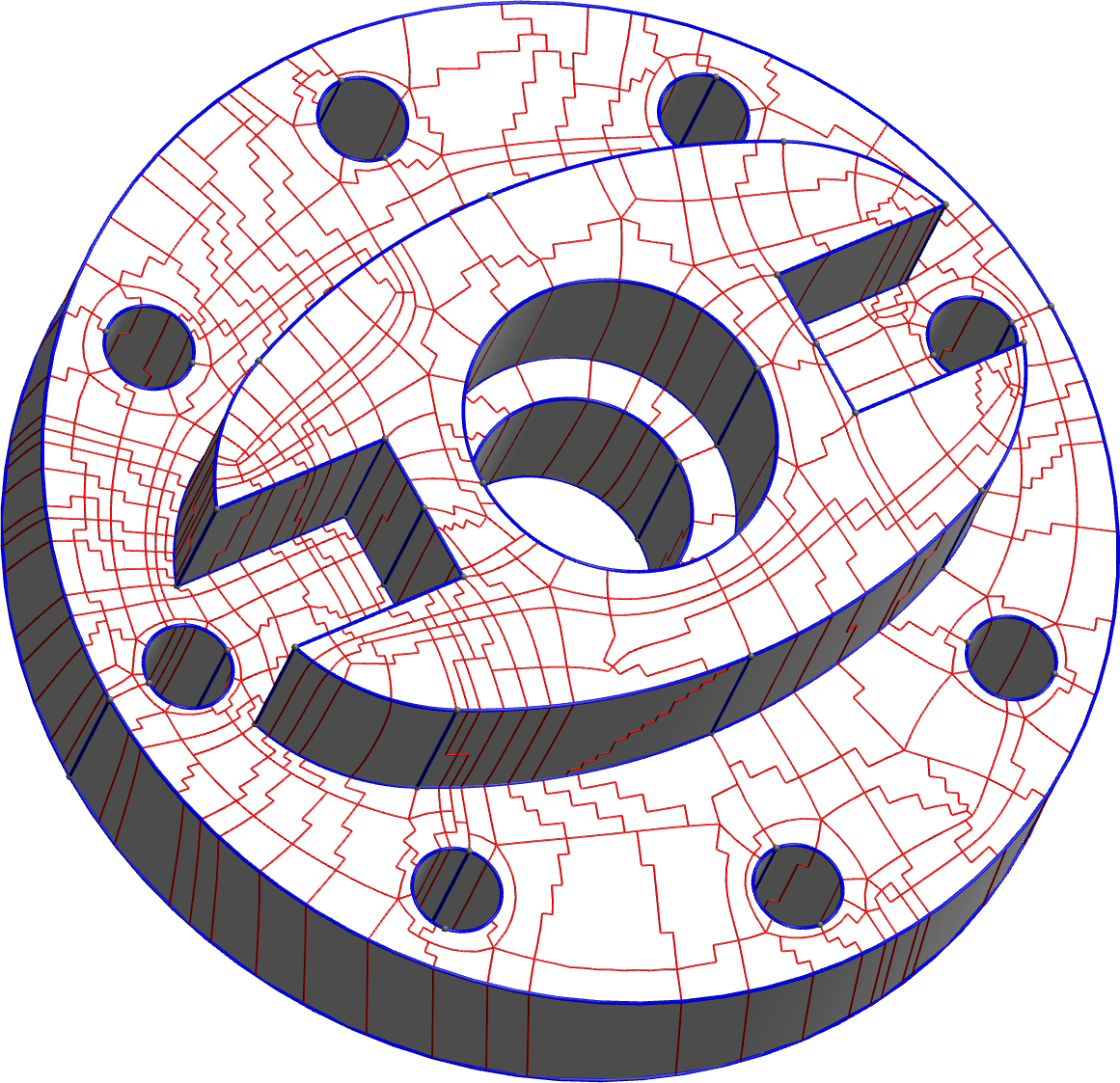
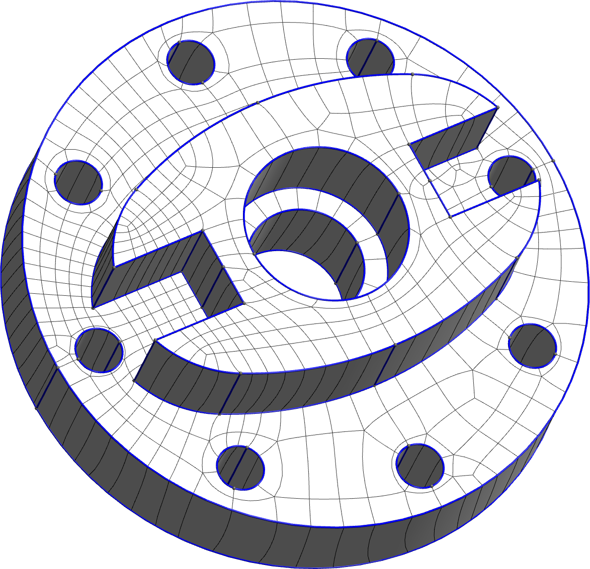
Even though we are able to produce good linear quadrilateral meshes (in terms of number of irregular vertices and quad shapes), they cannot be coarsened directly due to the density of their quad layout. The quad layout is a minimal partition of the mesh into structured quadrilateral patches, obtained by propagating separatrices from the irregular vertices until they reach other irregular vertices. A dense layout is illustrated in Figure 2: very few patches of the layout have more than one single quad of the initial mesh so the number of patches in the layout is about the same as the number of quads in the initial mesh. There are two main reasons for the quad layout to be very dense for our quasi-structured meshes:
-
•
Irregular vertices are not correctly aligned on the mesh, causing most separatrices to wind around the model until meeting an irregular vertex potentially far away.
-
•
Many irregular vertices do not match singularities from the cross field, but are present to accomodate size transitions and small CAD features. They are typically grouped in valence 3-5 pairs. These irregular vertices are not all necessary to produce good high-order quadrilateral patches.
In the next section, we will detail a methodology that allows to correct these defects and produce a mesh with a coarse quadrilateral layout.
3 Quadrilateral layout simplification
Given a quasi-structured quadrilateral mesh (the input mesh), we wish to obtain a block-structured mesh, having few irregular vertices but these vertices should be aligned to be able to extract coarse quadrilateral patches. To this end, we propose a slightly modified version of a method developed by Lyon et al. [6], adapted to incorporate strict compliance to the CAD geometry. In this section, we present our adaptation of the method.
The objective of the optimization is to produce a layout that is both coarse and consistent with the geometry, i.e., with patches that are not too distorted. There is a trade-off between these two criteria: the coarsest layout will have too much distorsion, and the layout with the best geometry is the layout of the input mesh, which, as previously shown, is very dense. To constrain the distorsion of the patches, we prevent two irregular vertices from aligning if the correponding deviation on the input mesh is larger than some prescribed angle .
The approach works as follows. First, a T-mesh, i.e., a quadrilateral mesh with T-junctions, is constructed on the given quasi-structured mesh. Every edge of this T-mesh, or arc, has an integer length, corresponding to the number of mesh edges lying on this arc. This integer length assignment is known as a quantization of the T-mesh. The idea of the method is to change this quantization in order to optimize the quadrilateral layout. In practice, this will involve assigning many arcs a length of zero. We formulate this task as an integer linear program (ILP), i.e., an optimization problem with integer variables and linear objective function and constraints. On typical models such as the ones treated in this work, the ILP is large, with thousands of variables and constraints. But such problems can be solved efficiently thanks to their linearity.
3.1 T-mesh construction
From every irregular vertex we propagate traces, as if we were drawing the mesh’s quad layout. However, the trace will not be extended until meeting another irregular vertex, but instead stop at some point when reaching another trace, creating a T-junction. Such a construction is sometimes called a motorcycle graph in reference to the movie Tron. Contrary to a classical motorcycle graph, traces do not stop immediately when reaching another trace. Instead, a trace should stop when it has encountered enough candidates for alignment; specifically, when it has met one candidate on each side of the trace that does not deviate by an angle larger than . Given a path between two vertices and , is the ratio between the integer length in the orthogonal direction () and in the tangential direction () [6]. Formally, we draw a fictitious cone around the trace of half-angle . The trace stops when it has intersected with two orthogonal traces on each side whose origin lies inside the cone. The rationale is the following: we want a trace to go far enough to have a couple of potential irregular vertices to align with, but we do not want it too long to prevent aligning irregular vertices far from each other, complexifying the quad layout in vain.
In order to comply with the CAD model, it is forbidden for non-CAD irregular vertices to collapse on a CAD curve. A simple way to address this is to set for traces lying on CAD curves. This will prevent the trace from diverting towards an irregular vertex away from the CAD curve. Note that, according to the stopping rule, a trace lying on a CAD curve will not stop until meeting another irregular vertex.
The constructed T-mesh consists of nodes for every irregular vertex and intersection of traces, arcs corresponding to segments of a trace between two nodes, and patches which are the quadrilateral regions bounded by the arcs. Every arc is assigned an integer length ; the set of integer lenghts are the variables of our optimization problem.
3.2 Quantization constraints
To achieve our goal of obtaining a coarse quantization that is valid and geometrically consistent, several constraints are enforced.
Non-negativity
It is clear that every arc should have a non-negative length: for every arc ,
| (1) |
Consistency
The quantization is said to be consistent if for every patch, pairs of opposite sides have the same total length. This ensures that the quantization implicitly defines a conforming quad mesh. For every patch with (ordered) sides , each side being a set of arcs, we write
| (2) |
Validity
For the quantization to be valid, irregular vertices must be separated by a strictly positive distance. This may seem complicated to formulate, but luckily the authors of [6] have proved a simple sufficient condition. Let be an irregular vertex and one of its traces and let denote the first trace that intersects whose origin lies in the cone around . Let denote the intersection, and the set of arcs from to . Then, for an irregular vertex to be separated from any other irregular vertex, it is sufficient that and are separated. Therefore, for every trace emanating from an irregular vertex, we set the constraint
| (3) |
As explained previously, the input mesh usually possesses many pairs of 3-5 irregular vertices that serve to satisfy size transitions. To further simplify the layout, we make an exception to the validity constraint to allow 3-5 pairs to collapse on each other. Such a collapse is valid as it results in a regular vertex. In practice, the constraint is not imposed if and form a 3-5 pair.
Geometric consistency
In order to ensure consistency with the geometry defined by the input mesh, we must explicitly separate irregular vertices whose traces intersect, but that do not lie in each other’s cone. To do so, for every irregular vertex , every irregular vertex that is outside the cone of is separated:
| (4) |
where is the intersection of and , is the total length from to , is the set of arcs from to , and is the cone half-angle for trace (which is either the user-prescribed angle , or 0 is the trace lies on a CAD curve).
3.3 Objective function
To obtain the coarsest possible quadrilateral layout, we need to minimize the number of patches. Let denote the integer dimensions of some patch. If or , the patch vanishes and does not contribute to the total number of patches. If , we add a single patch to our objective function. If or , it means that there remains T-junctions. To obtain a conforming quad layout, we split the patch into a grid of patches, each having dimensions and contributing as a single patch to the objective function. Hence, the objective that exactly promotes coarseness is the total integer area of the mesh:
| (5) |
However, this objective is nonlinear, and using it would not provide us an ILP. Instead, we minimize a weighted sum of arc lengths. The weight serves to help the solver prioritize arcs to collapse. To this end, we set the weight of an arc to be the inverse of its initial integer length . This gives the following objective function:
| (6) |
Note that this optimization problem is guaranteed to have a solution since the input mesh verifies every constraint.
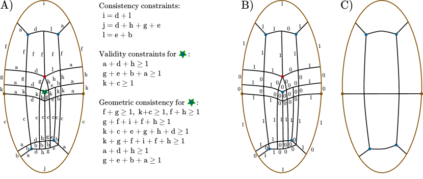
The previous T-mesh quantization simplification problem is illustrated on Figure 3, where we build the T-mesh of the quad mesh of an ellipse, which is not optimal because the irregular vertices are not aligned and there is an interior 3-5 pair. We list all the consistency constraints, and the validity and geometric consistency constraints associated to the central irregular vertex of valence three. Note that by using a single variable (e.g. length a along the ellipse) for multiple arcs, we already enforce the simple equality consistency constraints. In this particular example, the validity constraints are redundant with some of the geometric consistency constraints, but this is not always the case. The solution of the integer problem (values in B) contains lengths equal to zero and one, where zero corresponds to an arc collapse. By merging the appropriate vertices and smoothing the resulting quad mesh, we obtain the coarse layout in C. The horizontal line is kept because it connects the CAD corners (dots in brown), which are preserved in our formulation.
4 Block-structured quad mesh and high-order quadrilaterals
The optimized quantization implicitly defines a topological quad layout. In this section, we explain how we obtain a smooth and fine block-structured mesh. First, a conforming coarse quad mesh is extracted from the quantization; see 4.1, 4.2, 4.3. However this mesh has badly placed vertices and non-straight edges. Our approach to correct this is to subdivide the coarse patches to obtain a fine mesh; see 4.4, then smooth the fine mesh to optimize the placement of vertices and straighten the edges; see 4.5.
4.1 Edge and patch splitting
In the optimized quantization, some arcs will be assigned an integer length . These edges are split into sub-edges. To obtain a conforming quad layout, this split must be "propagated" by splitting the incident patches: if an incident patch has integer dimensions , and , it is split into sub-patches of dimensions ; if it is split into sub-patches of dimensions . Splitting patches of zero area is necessary to correctly merge vertices in the next step.
4.2 Vertex and edge merging
At this point we have a conforming layout but having many zero-length edges and zero-area patches. To get rid of these, we first identify groups of vertices that have zero distance between each other (formally, two vertices are in the same group if they are connected on the T-mesh by a path of zero total length). Every group of vertices is virtually merged into a single "center vertex". This effectively removes all zero-length T-edges. Then, edges bounded by the same pair of center vertices are virtually merged into one edge. This removes all zero-area patches, and leaves us with a clean topological mesh.
4.3 Vertex and edge placement
Vertices and edges need to be assigned a geometrical location on the model. This operation requires to pay attention to CAD consistency. Center vertices are chosen in the following way:
-
•
If some vertex in the group corresponds to a CAD vertex, the latter is taken as the center vertex (there is at most one CAD vertex in the group);
-
•
Otherwise, if some vertex in the group lies on a CAD curve, any vertex on the curve is taken as the center vertex (there is at most one such curve in the group);
-
•
Otherwise, any vertex of the group is taken as center.
Afterwards, edges are formed by taking the shortest path on the input mesh between the two centers they connect. If an edge lies on a CAD curve (i.e., some of the T-edges before the merge lied on a CAD curve), its corresponding path is the subset of the curve that connects the two centers.
4.4 Patch subdivision
Once we have a conforming quad mesh, we subdivide the coarse patches to refine the mesh. Note that opposite sides of a patch must have the same subdivision. Therefore, an integer width has to be chosen for every so-called "quad loop". A quad loop is a closed sequence of patches obtained by starting from a patch and iteratively go to its neighboring patch, following the same direction.
A target integer length is assigned to every edge, defined as the length of its corresponding path on the input mesh. Since this target length is not constant along the quad loop, the (rounded) mean target length is taken as the quad loop’s integer width. Following this process for every quad loop will assign to every edge an integer length. Finally, edges are subdivided into equal parts, and patches are subdivided by transfinite interpolation.
4.5 Smoothing
Once we have a fine mesh, we can proceed to smooth the mesh. We perform Winslow smoothing [10] which is the industry-standard technique for structured grid mesh generation. In an explicit optimization loop, each vertex is moved according to its neighbors. The Winslow coefficients are computed with a finite difference discretization of the Winslow equation [11]. Since this operation moves vertices away from the CAD surface, every vertex is projected back on it by finding the closest point on the surface.
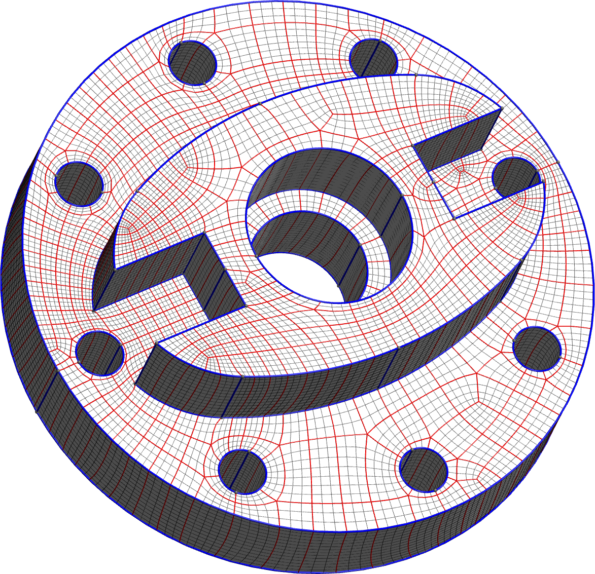
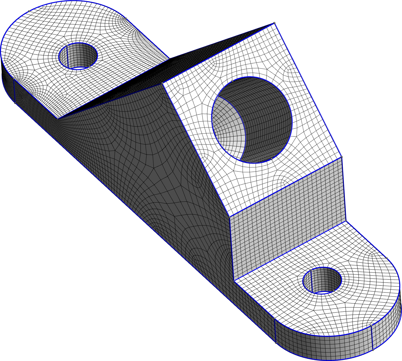
This smoothing tends to create squared quadrilaterals, so it is important that in the previous patch subdivision (4.4), the integer lengths assigned to the quad loops are chosen according the geometry. After smoothing, the block-structured quad mesh usually contains patches with rectangular shapes (e.g. Fig. 1.d.).
The explicit loop, with the FDM discretization of Winslow equations and CAD projections, is not guaranteed to produce valid quads (strictly positive Jacobian). In practice, the behaviour is generally satisfactory, but negative quads do appear at some concave corners. In the future, we will explore additional untangling techniques for surfaces, or directly optimize the high-order quad mesh produced later in the pipeline.
4.6 Extraction of high-order quadrilaterals
From the smooth block-structured quad mesh, we can extract high-order quadrilaterals. Assuming the elements are parametrized with Lagrange finite element functions of order , the process is straightforward:
-
•
For each vertex of the block structure, we create a high-order vertex.
-
•
For each edge of the block structure, we retrieve the two high-order extremities and we create interior high-order vertices along the curved edge via polyline equidistant re-sampling. Each new high-order vertex is projected on the CAD.
-
•
For each patch , we retrieve the four high-order corners and the four high-order sides, and we create interior high-order vertices with transfinite interpolation. Each new high-order vertex is projected on the CAD.
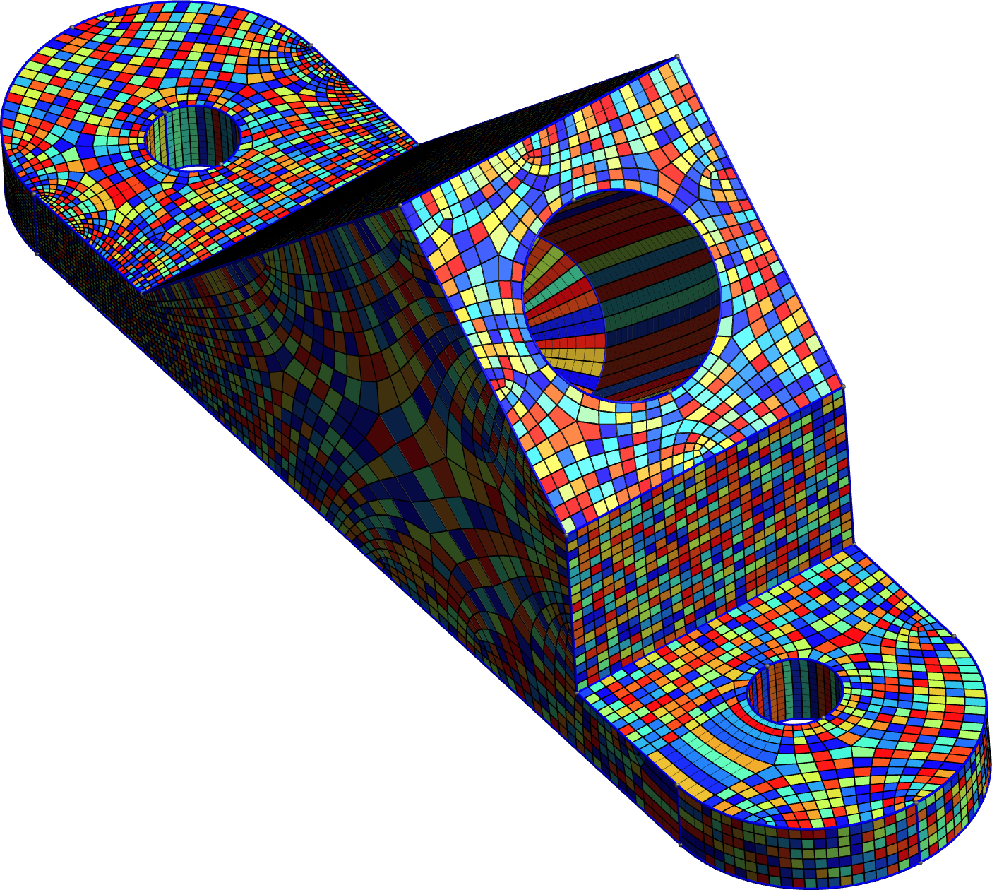
The above process generates high-order meshes with regularly spaced nodes. All the figures shown in this paper were produced with order five polynomials.
For better numerical properties, it is possible to produce Gauss-Lobatto spacing by slightly changing the curve re-sampling step. One could also build B-spline surfaces to better match the initial CAD geometry. In the future, we plan to implement multiple high-order representations and let the user choose the one best suited for his use cases.
Note that the position of the high-order nodes is entirely dependant on the result of the block-structured linear quad mesh smoothing. It may be interesting to employ high-order surface smoothing to further improve the mesh geometry, but such endeavour is challenging and we keep it for further work.
5 Results and discussion
[b] Model #Faces1 #Pinit2 #Irr3 #Vars4 #Pfinal5 Time6 QuadQS7 ILP8 Smooth9 \csvreader[no head, late after line=
-
1
Number of faces in quasi-structured mesh.
-
2
Number of patches in the quasi-structured mesh layout.
-
3
Number of irregular vertices in quasi-structured mesh.
-
4
Number of variables in the ILP.
-
5
Number of patches in high-order mesh.
-
6
Total run time from CAD to high-order mesh.
-
7
Proportion of time used for quasi-structured meshing.
-
8
Proportion of time used for solving the ILP.
-
9
Proportion of time used for smoothing and building the high-order mesh.
To validate our approach and its robustness, we apply it on several existing CAD models, and discuss its strengths and weaknesses.
Implementation
The complete pipeline is implemented in our meshing software Gmsh. The quasi-structured quadrilateral mesher and Winslow smoother are readily available in Gmsh. For solving the ILP we use lp_solve which is a free and open-source Mixed-Integer Linear Programming solver [13]. In our experiments, the complete pipeline is run on a single core on an average laptop computer.
CAD models
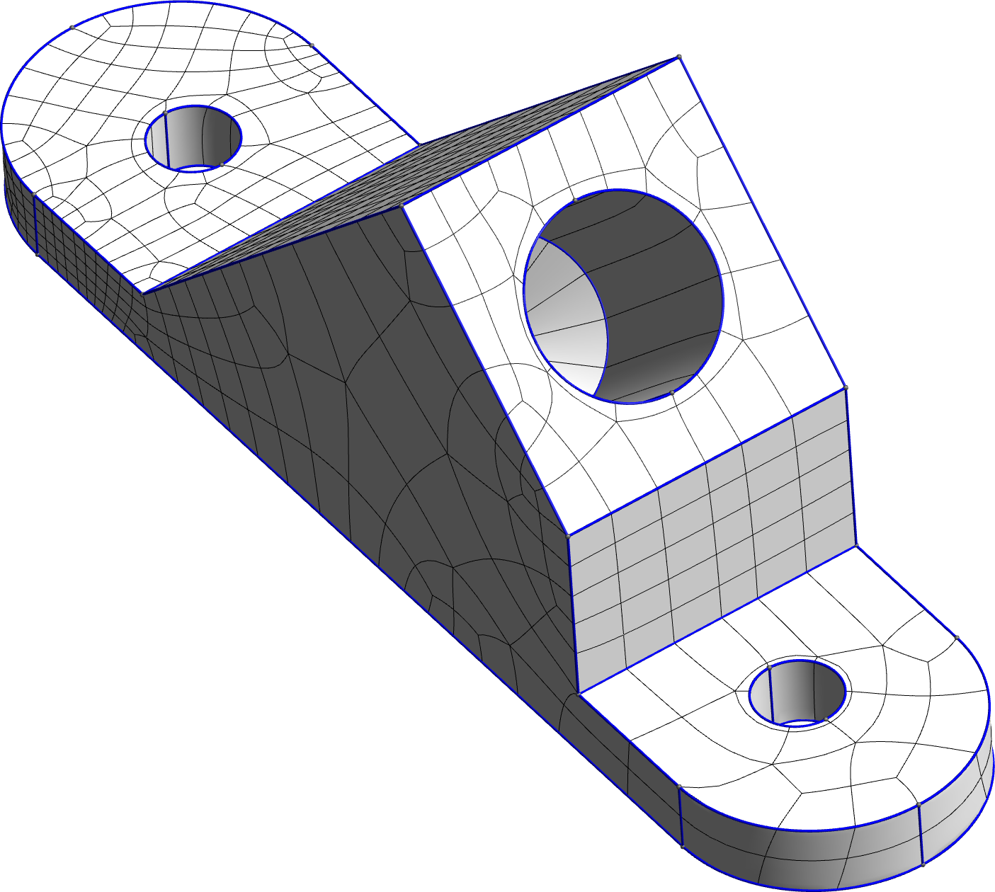
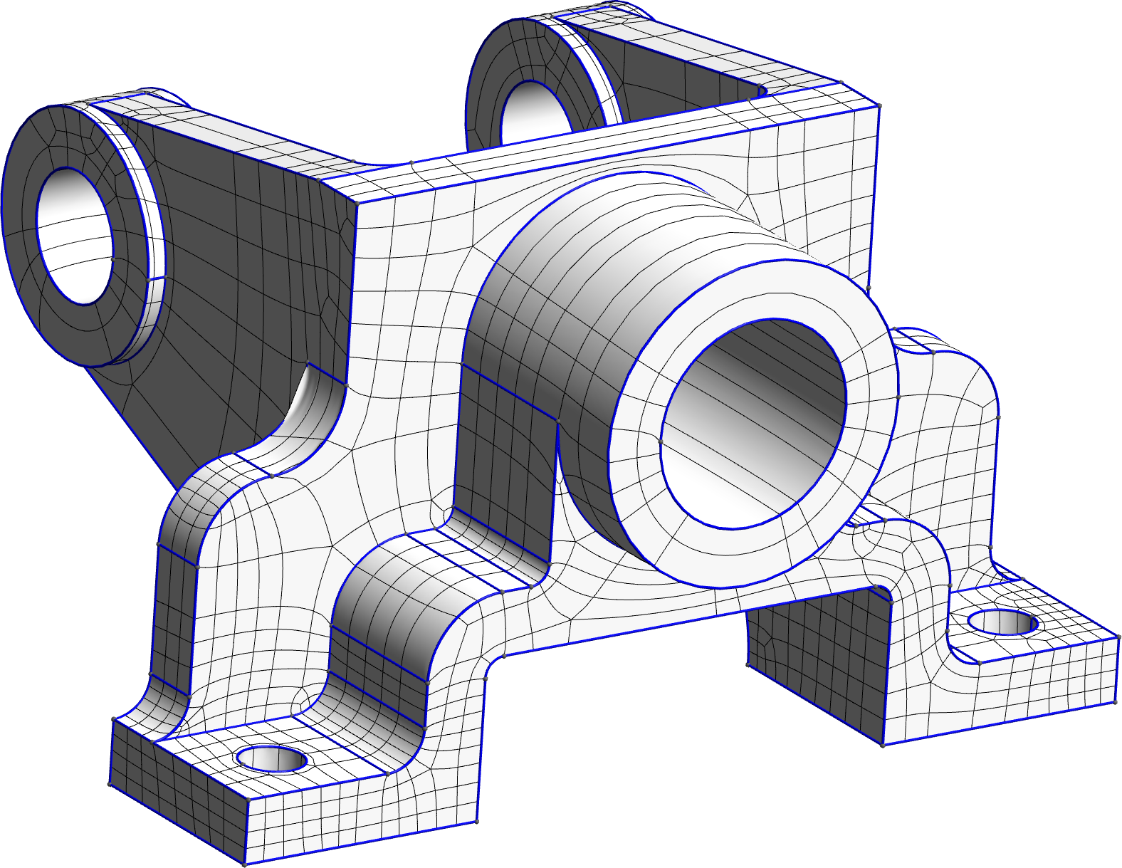
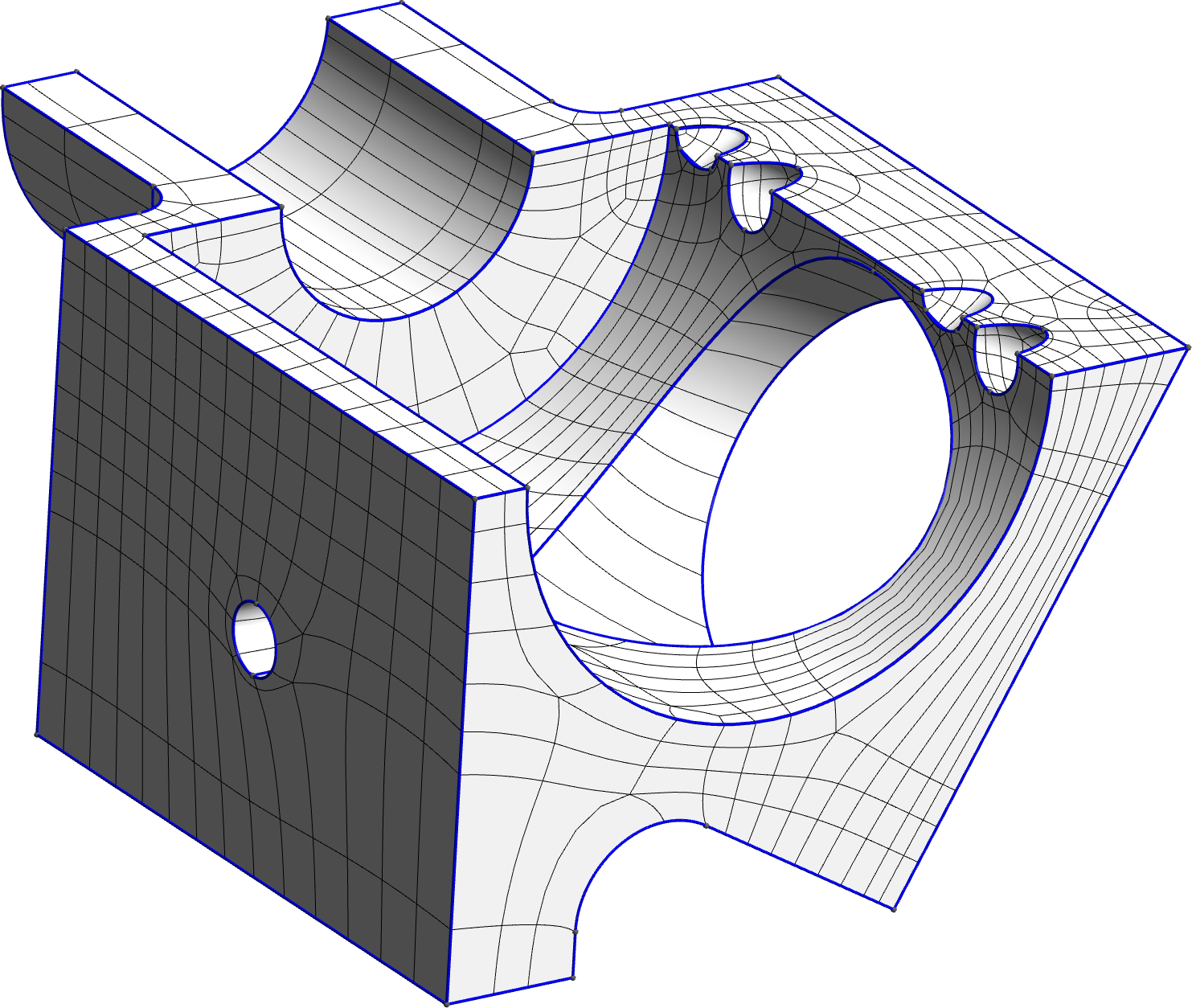
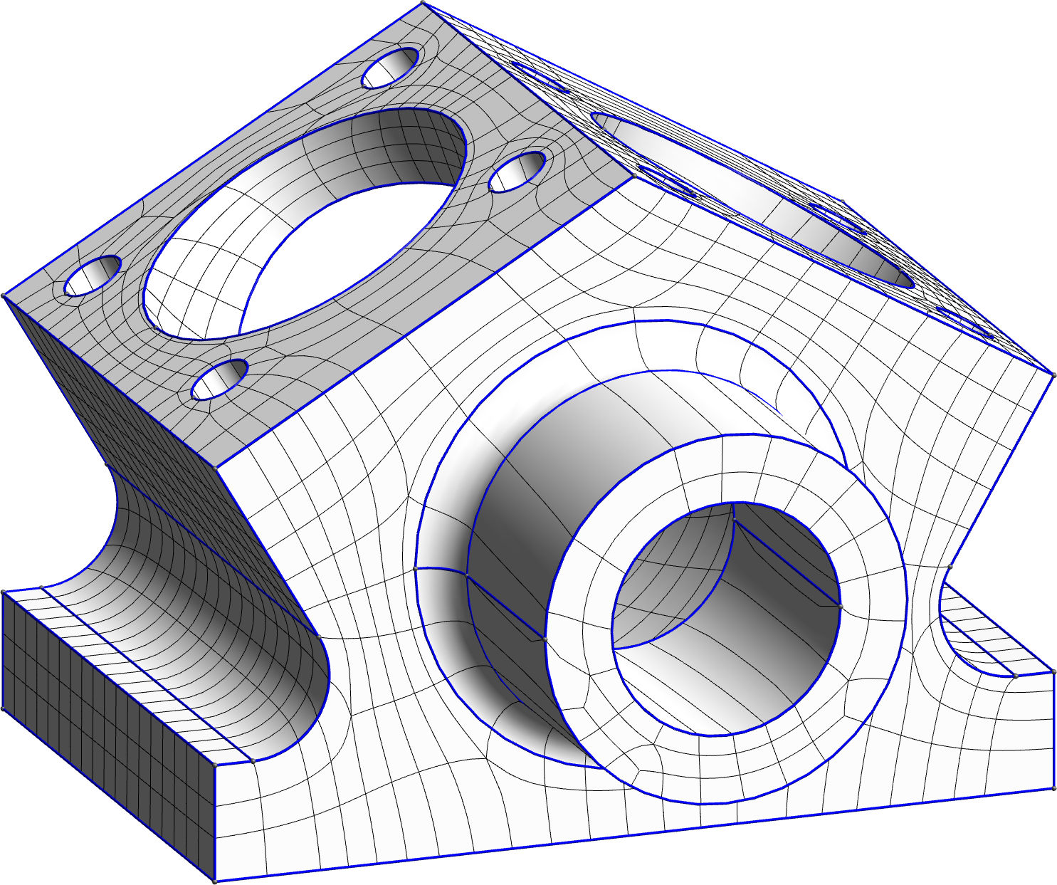
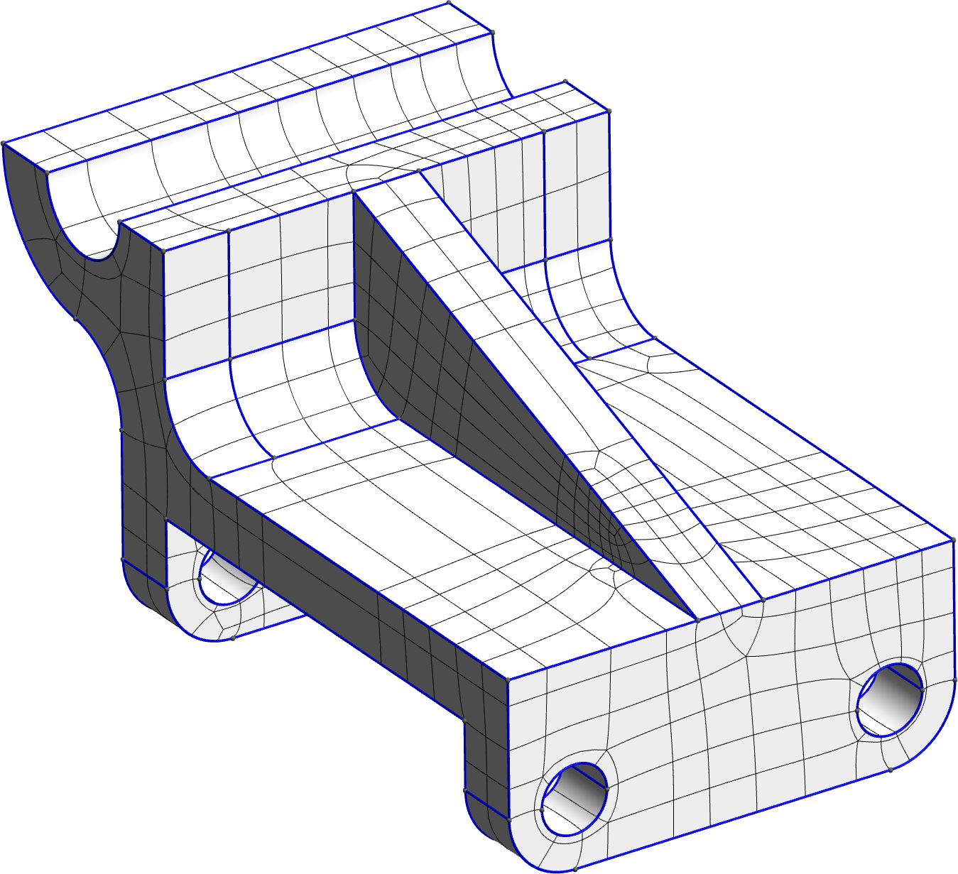
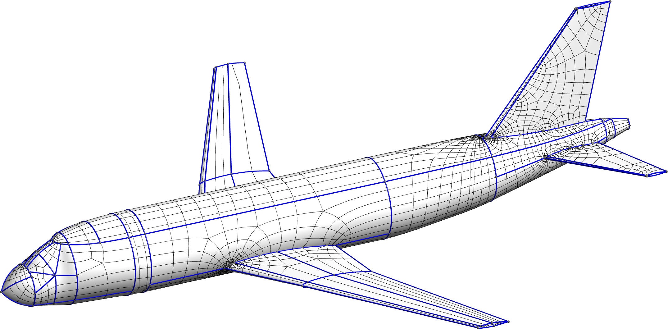
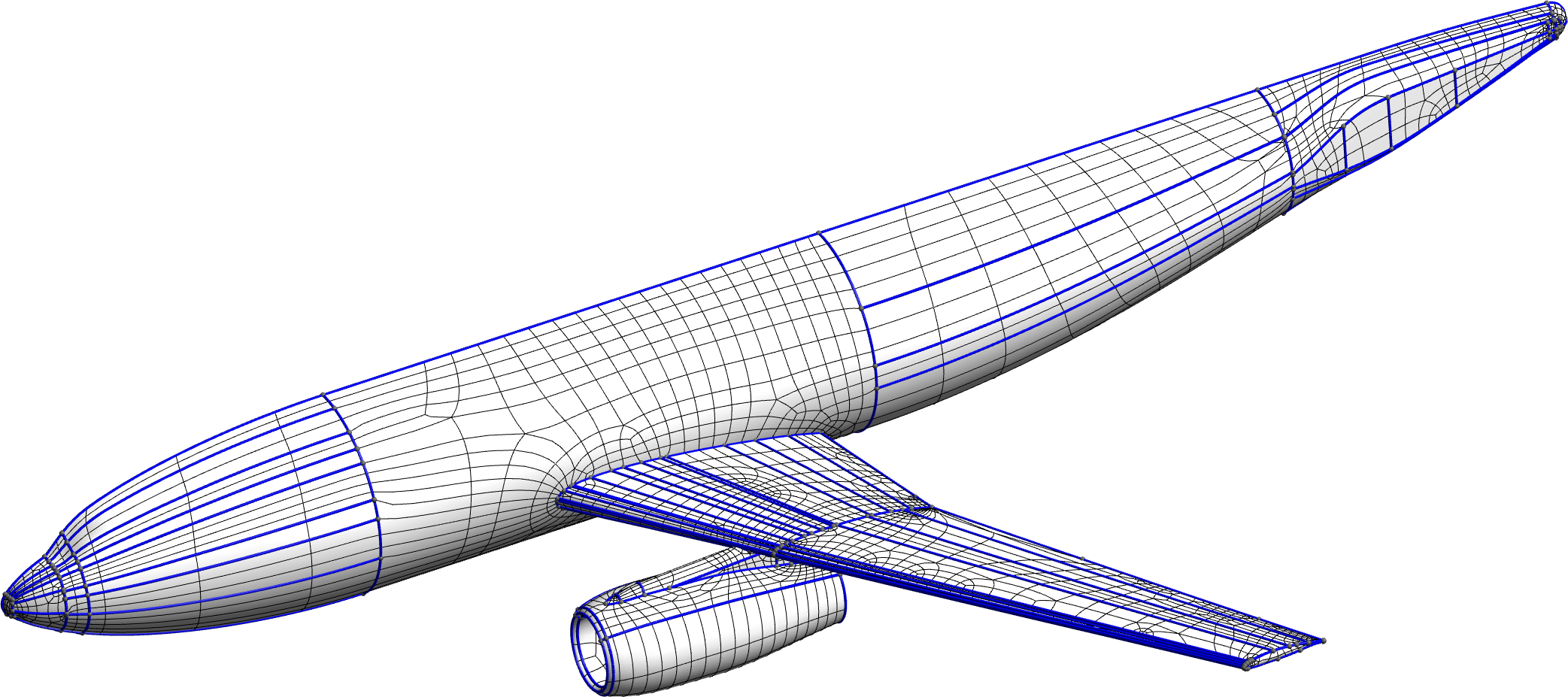
For illustration, we have chosen six CAD models from the MAMBO dataset [8] (M1 to M6) as well as two aircraft models, an Airbus A319 and the DLR-F6 [12]. As a maximal deviation we chose as we found that it achieves a good balance between coarseness and mesh quality. The order of the quadrilaterals is .
Discussion
First we can notice that the total run time, from a few seconds to a couple of minutes, is reasonable in an engineering analysis context, even on the more complex aircraft models. In all cases, solving the integer optimization takes a very small portion of the total run time. From this observation we are confident that ILP formulations are a viable approach to high-quality, high-order mesh generation. As the model complexity increases, smoothing takes a significant portion of the time.
Our method is able to significantly reduce the complexity of the quad layout, as can be deduced from the ratio which ranges from to . While the mesh coarseness is satisfying, we believe that it can be further simplified without affecting significantly the geometric consistency. We see two limitations that prevent a better simplification:
-
•
Once a 3-5 pair of irregular vertices has been collapsed into a regular vertex, this vertex cannot be collapsed further due to the validity constraints enforced on the former irregular vertices.
-
•
After quantization, many arcs have an integer length greater than 1, which significantly increases the number of patches after the splitting phase. This is due to our choice of objective function which is a linearization of the total mesh area.
By visual inspection we see that the quadrilaterals have low distortion, and while being coarse, they accurately capture the model’s geometry. The meshes we have produced are therefore perfectly suitable for high-order analysis techniques.
6 Conclusion and Future Work
In this work, we have presented a high-order meshing pipeline that is fast, effective and robust with respect to the CAD model in input. It combines our robust quasi-structured quad mesher together with a layout simplification based on an ILP formulation that allows to flexibly impose CAD compliance. An additional advantage is that the layout simplification only requires an unstructured quad mesh as input; there is no need for a seamless parametrization or a cross field which are usually hard to build robustly on CAD models. Although we have not achieved industrial-grade performance in terms of computational cost and coarseness, we are confident that further improvements can, paving the way for high-order analysis on arbitrarily complex CAD geometries.
In terms of computational cost, we should concentrate our efforts on the smoothing step which takes a large portion of the total time on large models. Another clue we would like to investigate is parallelism: a first "pre-simplification" could act on every CAD face separately while enforcing a quantization on the boundaries, after which a global layout simplification would finish the work.
In terms of coarseness, as previously said, we believe further simplification can be achieved without sacrificing geometric consistency. A first improvement is to allow collapsed 3-5 pairs to further collapse onto model curves or other irregular vertices. This could be achieved, e.g., using conditional constraints. Furthermore, by trading off computational performance, we could investigate the use of the exact objective function (5) with non-linear solvers. Finally, we note that the quality of the CAD model severely impacts the coarseness that can be achieved. This is particularly visible on the aircraft models in Figure 4 which possess many short CAD curves. Relaxing the CAD constraints by correcting such defects would allow to achieve a coarser result.
Acknowledgments
This research is supported by the European Research Council (project HEXTREME, ERC-2015-AdG-694020). Mattéo Couplet is a Research Fellow of the F.R.S.-FNRS.
References
- Hughes et al. [2005] Hughes, T. J. R., Cottrell, J. A., and Bazilevs, Y., “Isogeometric analysis: CAD, finite elements, NURBS, exact geometry and mesh refinement,” Computer Methods in Applied Mechanics and Engineering, Vol. 194, No. 39, 2005, pp. 4135–4195. 10.1016/j.cma.2004.10.008.
- Sevilla et al. [2008] Sevilla, R., Fernández-Méndez, S., and Huerta, A., “NURBS-enhanced finite element method (NEFEM),” International Journal for Numerical Methods in Engineering, Vol. 76, No. 1, 2008, pp. 56–83.
- Bommes et al. [2011] Bommes, D., Lempfer, T., and Kobbelt, L., “Global Structure Optimization of Quadrilateral Meshes,” Computer Graphics Forum, Vol. 30, No. 2, 2011, pp. 375–384. 10.1111/j.1467-8659.2011.01868.x.
- Tarini et al. [2011] Tarini, M., Puppo, E., Panozzo, D., Pietroni, N., and Cignoni, P., “Simple quad domains for field aligned mesh parametrization,” ACM Transactions on Graphics, Vol. 30, No. 6, 2011, pp. 1–12. 10.1145/2070781.2024176.
- Razafindrazaka et al. [2015] Razafindrazaka, F. H., Reitebuch, U., and Polthier, K., “Perfect Matching Quad Layouts for Manifold Meshes,” Computer Graphics Forum, Vol. 34, No. 5, 2015, pp. 219–228. 10.1111/cgf.12710.
- Lyon et al. [2021] Lyon, M., Campen, M., and Kobbelt, L., “Quad Layouts via Constrained T-Mesh Quantization,” Computer Graphics Forum, 2021. 10.1111/cgf.142634.
- Reberol et al. [2021] Reberol, M., Georgiadis, C., and Remacle, J.-F., “Quasi-structured quadrilateral meshing in Gmsh – a robust pipeline for complex CAD models,” arXiv:2103.04652 [cs], 2021.
- [8] Ledoux, F., “MAMBO dataset,” , ???? URL https://gitlab.com/franck.ledoux/mambo.
- Geuzaine and Remacle [2009] Geuzaine, C., and Remacle, J.-F., “Gmsh: A 3-D finite element mesh generator with built-in pre- and post-processing facilities,” International Journal for Numerical Methods in Engineering, Vol. 79, No. 11, 2009, pp. 1309–1331. 10.1002/nme.2579.
- Winslow [1966] Winslow, A. M., “Numerical solution of the quasilinear poisson equation in a nonuniform triangle mesh,” Journal of Computational Physics, Vol. 1, No. 2, 1966, pp. 149–172. 10.1016/0021-9991(66)90001-5.
- Knupp [1999] Knupp, P., “Winslow Smoothing on Two-Dimensional Unstructured Meshes,” Eng. Comput-germany., Vol. 15, No. 3, 1999, pp. 263–268. 10.1007/s003660050021.
- Brodersen [2002] Brodersen, O., “Drag Prediction of Engine-Airframe Interference Effects Using Unstructured Navier-Stokes Calculations,” Journal of Aircraft, Vol. 39, No. 6, 2002, pp. 927–935. 10.2514/2.3037.
- Berkelaar et al. [2004] Berkelaar, M., Eikland, K., and Notebaert, P., “lp_solve 5.5, Open source (Mixed-Integer) Linear Programming system,” Software, May 1 2004. URL http://lpsolve.sourceforge.net/5.5/.