✓\checkmark
SmartHand: Towards Embedded Smart Hands for Prosthetic and Robotic Applications
Abstract
The sophisticated sense of touch of the human hand significantly contributes to our ability to safely, efficiently, and dexterously manipulate arbitrary objects in our environment. Robotic and prosthetic devices lack refined tactile feedback from their end-effectors, leading to counterintuitive and complex control strategies. To address this lack, tactile sensors have been designed and developed, but they are either expensive and not scalable or offer an insufficient spatial and temporal resolution. This paper focuses on overcoming these issues by designing a smart embedded system, called SmartHand, enabling the acquisition and real-time processing of high-resolution tactile information from a hand-shaped multi-sensor array for prosthetic and robotic applications. We acquire a new tactile dataset consisting of 340,000 frames while interacting with 16 objects from everyday life and the empty hand, i.e., a total of 17 classes. The design of the embedded system minimizes response latency in classification, by deploying a small yet accurate convolutional neural network on a high-performance ARM Cortex-M7 microcontroller. Compared to related work, our model requires one order of magnitude less memory and 15.6 fewer computations while achieving similar inter-session accuracy and up to 98.86% and 99.83% top-1 and top-3 cross-validation accuracy, respectively. Experimental results of the designed prototype show a total power consumption of 505 mW and a latency of only 100 ms.
I Introduction
Robotic hands and prosthetic devices provide robots with humans’ ability to interact with the surroundings and restore lost abilities for amputees. The preeminent modality of choice for robotic devices that need to interact with the environment is vision [1, 2]. Optical sensors are performing well, are inexpensive, and mature computer vision algorithms exist for every level of processing power. On the other hand, there are tasks in which optical information is insufficient or leads to disproportionately complex control strategies. One such task is the manipulation of arbitrary objects with an articulated end-effector. Vision is required to find correctly the object and the position of the end-effector, but once contact is made, the robot cannot tell if the object is fragile or robust, if the end-effector has a good grip or if the object will slip from its grasp. For this reason, a recent trend is to develop non-visual technologies and methods to provide a robot with those capabilities.
In nature, organisms have evolved a useful modality for manipulating their surroundings: the touch. Science is often inspired by nature, so in order to improve the ability of robots and prosthetic devices to manipulate objects in the environment, tactile sensors have recently gained considerable attention. Even though much research has been conducted [3, 4, 5, 6, 7], the task of developing a tactile sensor with a resolution comparable to the human hand, with similar robustness as well as flexibility, remains an open challenge [8]. Object grasping and manipulation are natural abilities for healthy human beings, but it is a very difficult task for robotic machines. Besides the sense of touch, humans can elaborate sensory and perceptive inputs during object interaction. The inertial properties of the object are immediately perceived, and the corresponding adjustments are performed in real-time during the manipulation. This is an essential ability that a robotic machine has to be equipped with in order to optimally interact with objects. In fact, the weight, the mass distribution, and the inertial resistance are all factors to be considered for efficient and safe robotic motor planning. However, no satisfying solution has yet been proposed due to the lack of well-defined sensing equipment that provides useful data for estimating the inertial parameters [9].
State-of-the-art sensor solutions, from academia and industry, are typically hard to manufacture, expensive, and lacking in temporal as well as spatial resolution [10, 11, 12]. The majority of the solutions mainly focus on replicating the fingers tips [13, 3, 14] or have sensors covering only a limited part of the hand palm [15]. Recently, a remarkable approach has been proposed by Sundaram and colleagues[8]. For the first time in literature, the authors have created a scalable tactile glove (STAG) that presents the full coverage of the human hand, providing tactile information with high spatial resolution. A tactile dataset is collected while interacting with 26 daily life objects for several minutes each. A convolutional neural network (CNN) is subsequently applied for classifying the objects and the empty hand. To be noted that the proposed setup with offline sensor data processing based on several-minute recordings introduces long latency, making it sub-optimal for a real-world application where a prompt response in the range of milliseconds is desired. Moreover, embedding multi-sensors in small integrated systems is actively researched thanks to its advantages for closed-loop control of the robotic devices [16]. Weiner and colleagues [3] propose a fingertip system integrating several sensors that are miniaturized to fit in the very limited space of a fingertip. Besides the integration of sensors, a smart processing unit, e.g., microcontroller units (MCUs), that can process the acquired sensor data at the edge would enable a real-time response of the whole system.
Recent developments in edge processing units and tinyML [17] make it possible to bring the data processing close to the sensors. Along with efforts in designing and deploying tiny machine learning and deep learning models on the edge, nowadays edge devices are becoming increasingly smart and can interpret sensor data and translate it into actionable information in real-time [18]. A drawback of low-power edge computing is that the resources available on MCUs with milli-watt power consumption are very limited making it impossible to deploy big and complex models. Thus, a conscious design of tiny yet accurate models is necessary, by taking into consideration the memory availability and computational capability of the underlying processor.
This work is a step towards equipping robotic and prosthetic devices with a smart sense of touch by presenting a smart embedded system, called Smarthand, capable of reading and processing high-resolution tactile information in real-time.
The main contributions of this paper are as follows:
-
•
We reproduce a multi-array tactile sensor in the shape of a human hand with high spatial resolution [8] and integrate it in a full system, called SmartHand, able to acquire tactile and hand movement data and process it in real-time.
-
•
Three operational modalities for different use-cases were implemented, and a large dataset was collected while interacting with 16 objects from everyday life in addition to the empty hand. The dataset is open-source released111Available at https://iis.ee.ethz.ch/~datasets/smarthand..
-
•
We design a novel CNN which requires one order of magnitude less memory footprint and 15.6 less computation with negligible accuracy drop of 0.21% when eight input images are given or around 2% when a single frame is given, compared to the original network on the STAG dataset from MIT [8].
-
•
We successfully deployed the trained model on an ARM Cortex-M7 MCU close to the sensor node, hosted by the SmartHand, to enable smart edge computing. The top-1 and top-3 classification accuracy is respectively 98.86% and 99.83% when seven-fold cross-validation is performed on the full acquired dataset. While the inter-session top-1 and top-3 accuracy values are respectively 49.63% and 77.84% with only one input frame, which significantly increases the temporal resolution by reducing the system response from several minutes to sub-second.
-
•
Experimental measurements show that our proposed SmartHand, with embedded CNN, can infer the contacted object with a low latency of 100 ms while consuming a total power of 505 mW.
II System Architecture
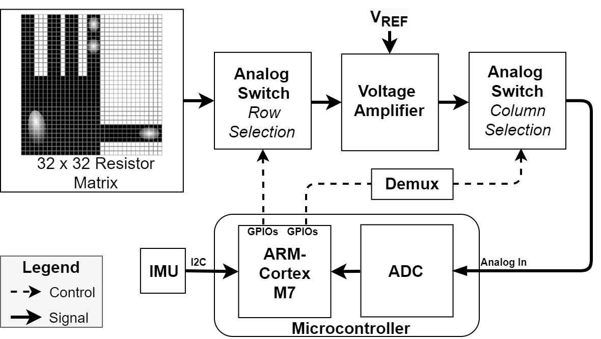
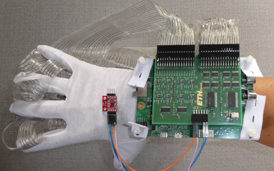
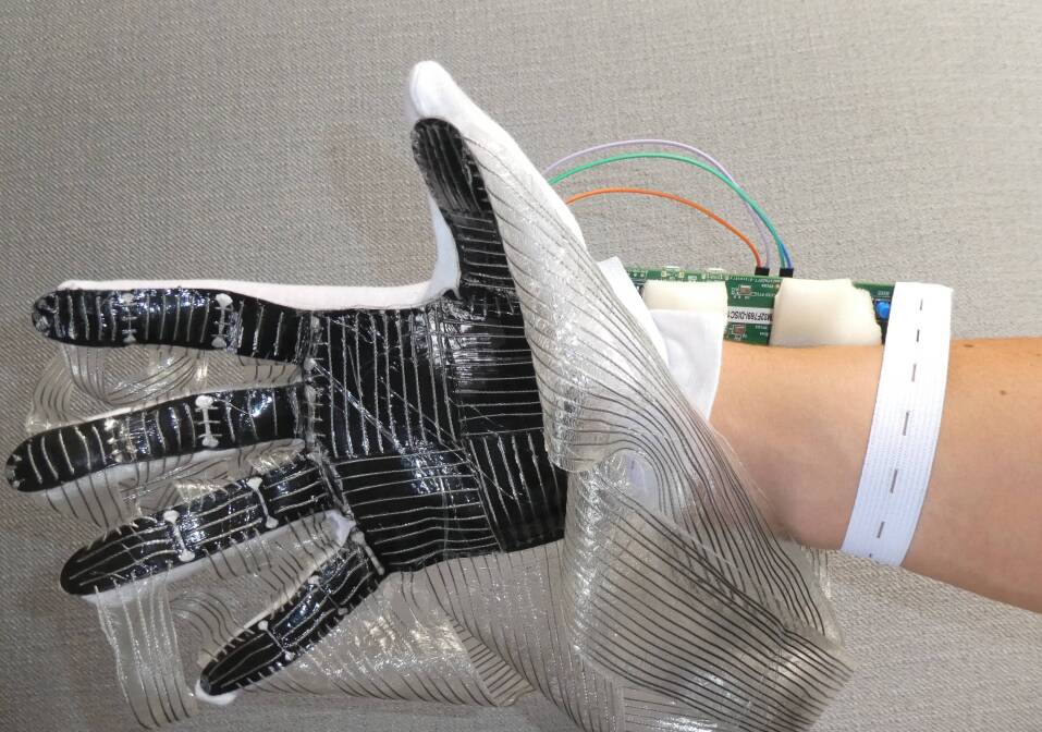
Fig. 1 depicts the block diagram and the architecture of the designed Smarthand. It consists of a low cost resistive tactile sensor based on a conductive polymer composite (CPC) as in [8], an analog front-end (AFE) to read the tactile data, an inertial measurement unit (IMU) to gain additional movement information, and an MCU for system control and onboard signal processing. Fig. 2 and Fig. 3 show the full system assembled and worn.
II-A Tactile sensor
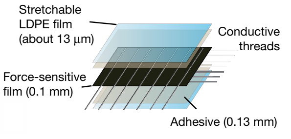
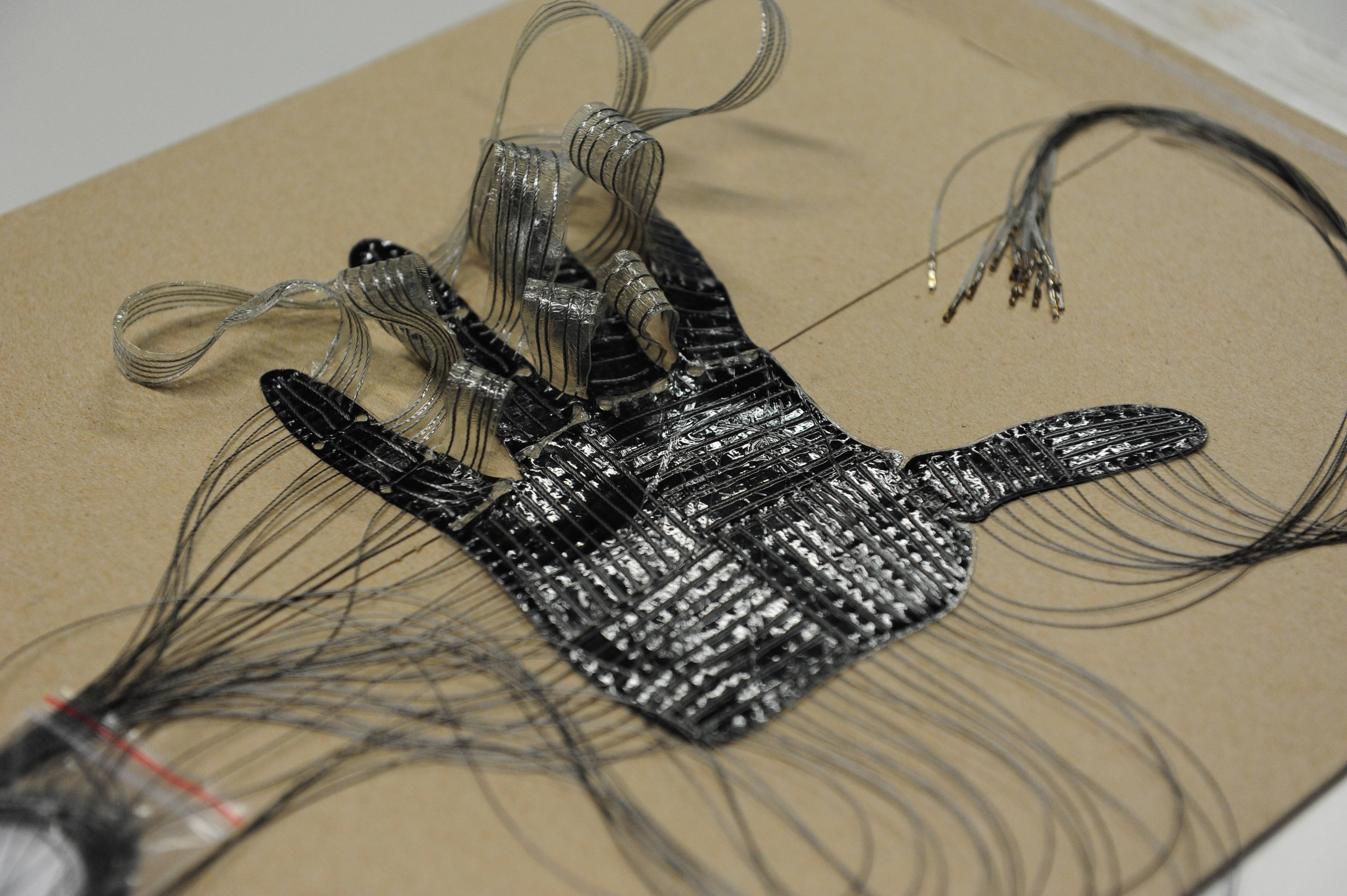
Following the fabrication procedures described by [8], a tactile sensor with high spatial resolution was produced in our laboratory. The sensor consists of a CPC, called Velostat, sandwiched between two orthogonal sets of electrodes, as shown in Fig. 4. Based on the concept of force sensitive resistor (FSR), in response to increasing normal forces, its resistance decreases, which can be read with a dedicated analog front-end. There are 32 electrodes running across each of the two sides of the force sensitive film forming a grid.
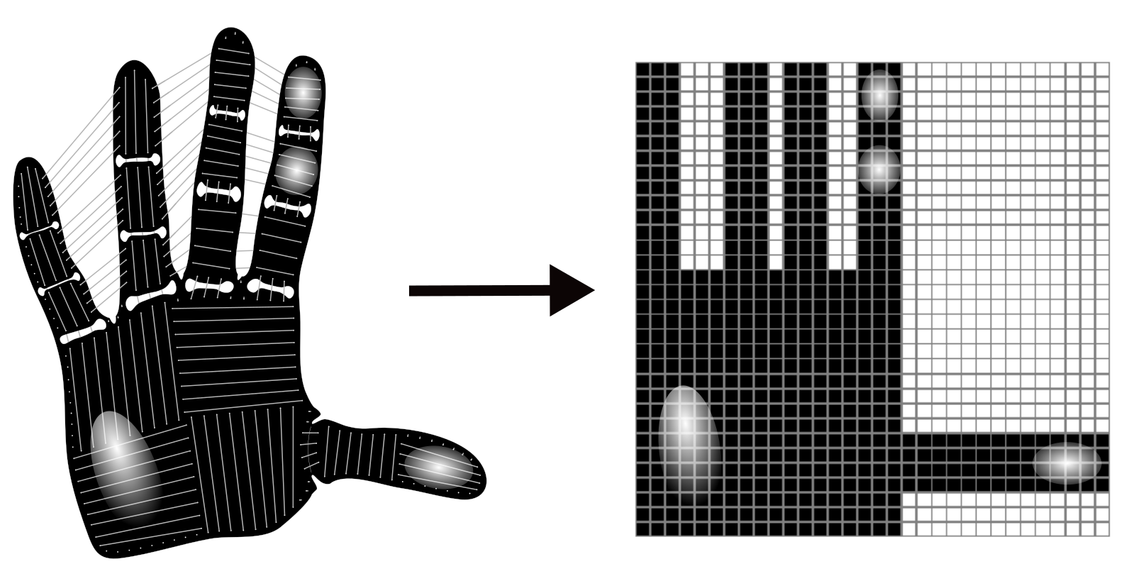
The function of the sensor does not depend on its shape, thus it can be fabricated in arbitrary forms and sizes. To obtain comparable results and capture useful data during object interaction, the sensor was fabricated as similarly as possible to [8]. Fig. 5 shows the finished sensor laminate before being attached to a thin cotton glove. Because the active sensor area is shaped like a hand, there are 548 physical crossings of electrodes. However, to preserve the spatial relation between taxels, or sensor points, and make it easier to work with the sensor data, all 1024 available taxels are read. By arranging the read values in a 32x32 matrix, an intuitive and natural representation of the sensor can be constructed, as shown in Fig. 6, and will be referred to as tactile frame, or simply frame.
II-B Readout Circuit
The authors in [8] designed a readout circuit for their STAG. Abstracting from its physical structure, the tactile sensor is a network of resistors formed by the cross-talks between the two orthogonal sets of 32 electrodes. Each cross-talk can be seen as a simple resistor with variable resistances depending on the pressure applied to the sensor glove. The readout circuit has to be able to read each of these resistance values correctly. The circuit proposed by the authors is based on the electrical isolation scheme [19], which ensures that there is only one current path when measuring the resistance between two electrodes. Our implementation is based on this original design but improved by using a more powerful MCU featuring a higher precision analog-to-digital converter (12-bit).
II-C Movement sensor
We additionally integrate an IMU for acquiring accelerometer and gyroscope data to collect hand movements during object interaction. The used IMU is MPU-9250 with a sampling frequency of and a resolution of 16-bit for both the accelerometer and the gyroscope.
II-D Edge processing unit
The embedded system requires an MCU with the ability to drive and read the tactile sensor, as well as directly run neural network inferences with the acquired data and take action based on the inference, e.g., actuating the motors of the robotic arm. For a fast development of the prototype, the STM32F769NI discovery board was chosen, featuring an ARM Cortex-M7 core. With its 2 MB of Flash memory, 532 kB of RAM, and a maximum clock speed of 216 MHz, it is one of the most highly-performing MCU in the low-power ARM Cortex-M family. It comes with the software tool STM32CubeMX, from STMicroelectronics, employed for generating initialization code, compiling, and flashing. X-CUBE-AI is an expansion package for STM32CubeMx that allows fast deployment of neural networks on STM32 MCUs.
II-E Operational Modalities
The firmware of the system is implemented such that three operational modalities are available for different use-case scenarios. A basic timer peripheral on the MCU is used to clock the applications.
II-E1 Data collection
This modality is used for acquiring a complete dataset. The system waits for a ‘start’ command, given either by pressing a button on the discovery board or sending the character ‘r’ via the universal asynchronous receiver-transmitter (UART) protocol to the MCU. If either of these two events is detected, the base timer is triggered at a rate of 100 Hz, and the tactile along with IMU data is collected. The external synchronous dynamic random-access memory (SDRAM) on the discovery board was utilized as intermediate storage for tactile data, while the IMU data is sent directly after its acquisition. After a configurable number of frames has been collected, the data acquisition stops and immediately sends the content of the SDRAM to a connected computer, and the system returns to the idle state waiting for the next ‘start’ command. The SDRAM can store a maximum of 4096 tactile frames, limiting one single interaction to a maximum of about 40 seconds with a data collection rate of 100Hz. The acquisition frequency can be reduced if a longer recording is desired.
II-E2 Real-time data visualization
A graphical user interface (GUI) designed using Python is implemented and can be used to visualize the tactile sensor data on a computer screen directly. Once the ‘start’ command is received, the base timer is activated, and the tactile frames are collected at 10 Hz and directly sent to the connected computer via UART. To stop the visualization, either the button on the discovery board has to be pressed again, or the character ‘p’ needs to be sent to the system. The GUI displays each frame as a 32x32 matrix and provides two buttons, labeled ‘Run’ and ‘Pause’, which respectively send ‘r’ or ‘p’ to the system, giving the option to control the data visualization from the same interface.
II-E3 Smarthand system
This modality leverages the full system by not only reading tactile data but also processing it real-time on the MCU using a deployed neural network. The data acquisition starts after pressing the button on the discovery board with the base timer configured to 8 Hz. The sensor data is read and processed by the neural network on the MCU. The system clock is configured to 216MHz to maximize the inference speed. To evaluate the performance of the SmartHand system, a second Python GUI is developed, which displays the result of each network inference and its corresponding input frame. To simultaneously process the frame onboard and visualize it in real-time, a direct memory access (DMA) controller is used for sensor data transmission. It is to note that in this case, the connection to the computer serves merely for the verification purpose of a demo, the system can fully function independent of any processing engine other than the onboard MCU, and the output of the neural network inference can be used in real-time for any robotic or prosthetic control. Fig. 7 displays a snapshot of a demo video in this application modality. The SmartHand is worn like a glove, and the tactile data during the interaction with a mug is acquired and classified immediately with the onboard embedded CNN. The classification output is displayed in real-time on the screen.
III Neural Network
This section describes the model design, the training and the evaluation of the neural network used for processing the sensor data, and its embedded deployment on the onboard MCU.
III-A Convolutional Neural Network Design
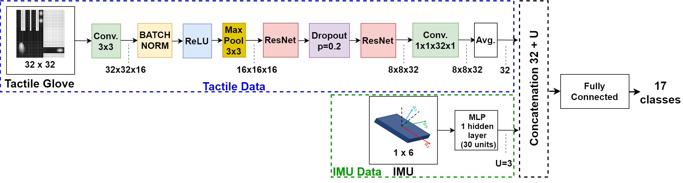
Because of the inherently spatial information present in the sensor, a CNN architecture was chosen to process the tactile data. As in [8], we choose a model architecture based on ResNet-18 [20], but fully redesign it by taking into consideration hardware resource constraints. Fig. 8 depicts the proposed model architecture framed with a blue dashed line. It uses multiple stages of convolutions, including two residual blocks, to extract features from a single input frame. Finally, a fully connected layer is used for the classification. Compared to [8], we restrict the number of input frames to a single one directly reducing the latency. Another adaptation is a four-fold reduction of convolution filters. This decreases significantly the inference speed thanks to the reduced model complexity.
To include the IMU data, a simple multi-layer perceptron (MLP) with one hidden layer consisting of 30 hidden units is added to extract the feature representations. The output layer of the MLP consists of 3 neurons and is subsequently concatenated to the features of the tactile data before the final fully connected layer for the classification. This method is motivated by literature [16, 21, 22], in which the features of the individual sensors are first extracted and then concatenated. This additional branch featuring IMU data can be added or removed depending on the application.
III-B Training and validation
The model is trained using PyTorch on GeForce GTX 1080 Ti GPUs with CUDA framework. Two validation methodologies were employed. First, the data is randomly split, and seven-fold cross-validation (CV) is performed. Second, the data is split by session to consider the inter-session variability. One session is kept as a validation set, while the remaining four are used for training. In both cases the model is trained for 60 epochs with cross-entropy loss and Adam optimizer.
III-C Emdedded implementation
The X-CUBE-AI expansion package for STM32CubeMx is used for deploying the trained CNN on the MCU. For the embedded deployment, the model is trained by leveraging the full dataset. It is then saved in ONNX format and imported in STM32CubeMx. The tool generates an application template code, to which the user code to read the data can be added and the inference performed.
IV Datasets
Two datasets are evaluated in this paper. In order to reproduce the results in [8] and to fairly compare our proposed methods, we use the dataset provided by the authors. With the goal of integrating a complete system capable of sensor data acquisition and online data processing, we acquired our dataset using the in-house produced tactile sensor glove.
IV-A MIT-STAG Dataset
The work by Sundaram and colleagues [8] from MIT proposed for the first time a tactile glove covering the full hand, called STAG, based on the concept of FSR using a CPC, with high spatial resolution. A total of 135,000 frames of tactile data was collected together with synchronized video footage in three recording sessions, during each of which the sensor glove was worn throughout the entire session. This dataset contains several minutes of interaction with 26 different objects from everyday life. Tactile frames were collected at a rate of about 7.3 Hz. All objects were manipulated in a repeatable way, mostly pushing the sensor from the top onto the object lying on a table. The frames corresponding to the actual touch of the object are chosen by comparing the values with a threshold found from an empty-hand dataset. This threshold value is found for each taxel to account for any internal stress caused by the sensor conformation. The authors select N frames from the several-minute recordings by either random selection or clustering to construct the input samples to the neural network. The dataset is publicly available222http://stag.csail.mit.edu/.
IV-B ETHZ-STAG Dataset
Following the analogous procedures of fabrication, we created our own STAG at ETH Zurich. A large dataset was collected with the data collection modality described in Sec. II-E in five recording sessions. Instead of synchronous video footage, synchronous accelerometer and gyroscope data are collected from an IMU. During every recording session, 16 different objects were manipulated for 40 seconds each while continuously collecting tactile and IMU data at a rate of 100 Hz. The manipulations were done in the same manner as in [8] to increase repeatability between recording sessions. The valid frames of actual object contact are marked by comparing to a threshold value for each taxel, as in [8]. We construct these thresholds by finding the highest possible value that a taxel can assume using more than 20,000 additional empty-hand-frames of different hand poses without object contact. Finally, a total of 340,000 frames are available.
V Results
We present the results of object classification using our proposed CNN and compare it to previous work [8]. In addition, we report the outcome of the embedded implementation in terms of multiply-and-accumulate operations (MACCs), memory usage, and inference time on the selected MCU.
V-A Neural network performance
First of all, we compare the accuracy of our proposed model with the original network on MIT-STAG dataset [8]. The authors randomly select N frames from each recording as the input to the CNN. We reproduce their results and train our model on the same dataset with the same splitting. As shown in Fig. 9, despite the significantly smaller size of our model, the accuracy is comparable, especially for N = 8, where the accuracy drop is only 0.21%. However, N = 1 would introduce less computational burden for a real-time application scenario yielding lower latency. Again, our model performs comparably to the original one, with less than 2% accuracy drop with N = 1.
The second step is to evaluate the model performance on our dataset collected by the STAG fabricated in-house and integrated into our proposed system. With our dataset, we consider only N = 1 and take all the valid frames instead of randomly selecting subsets of valid frames from each recording. This reduces the several-minute latency of previous work and enables the real-time response of the entire system. Fig. 10(a) shows the results for the seven-fold cross-validation with random splitting on the whole dataset without considering inter-session variability. The top-1 and top-3 accuracy values, i.e., the correct class is the one with the highest predicted probability, and the correct class is among the ones with the three highest probabilities, are respectively 98.86% and 99.83, demonstrating the effectiveness of the neural network to learn the full data distribution. Whereas, by considering the inter-session variability, we obtain the top-1 and the top-3 accuracy of 49.63% and 77.84%, respectively.
V-B Embedded implementation
We subsequently proceed with network deployment on the MCU. Here the main advantage of our proposed model becomes evident. In fact, the proposed network in [8] is too big for the selected MCU making it impossible to be embedded onboard. Table I reports the comparison between the two networks. Note that the inference time reported for the original network is obtained by reducing the input convolution filters from 64 to 54 since it is impossible to deploy the full network due to memory constraints. Our model requires one order of magnitude less memory, making it possible to be deployed. The number of computations is reduced by 15.6 in terms of MACCs, yielding more than 12 speedup for the inference time. This effectively enables a system with real-time response.
| Project | MACC | Flash | RAM | Inference time |
|---|---|---|---|---|
| Cit. [8] | 73.3 M | 2.77 MB | 196 kB | >1.2 s |
| This work | 4.7 M | 177 kB | 52 kB | 100 ms |
V-C Sensor fusion
The IMU orientation in the form of Euler angles is directly fed into the MLP, or only accelerometer or gyroscope data is used. Unfortunately, no configuration has provided an improvement over the model using only tactile data. The usage of IMU data in this application scenario is not very meaningful, as all the objects were mostly manipulated from the top. In a real application scenario with robotic hands, the information about end-effector orientation is crucial and needs to be included at various stages of the processing loop. Accordingly, the integration of the IMU is a step towards a usable and practical system.
V-D Power measurements
Finally, we measure the power consumption of the full system with the IMU and the MCU supplied at 3.3 V, and the readout circuit at 5V. The measured active power is 505 mW, and the idle power is 185 µW.
VI Conclusion
This paper presents SmartHand, a smart embedded system that is a step towards equipping robotic and prosthetic devices with a sense of touch by demonstrating the feasibility of acquiring useful tactile data with high spatial and temporal resolution from a highly customizable tactile sensor. Starting from replicating a state-of-art tactile sensor with high spatial resolution, SmartHand focuses on maximizing the temporal resolution by reducing the latency in the system response thanks to the execution of a compact deep learning model for the classification task directly close to the sensor node. A working prototype of SmartHand is designed and implemented to carry out solid experimental evaluations that have shown a power consumption of 505 mW and a latency of 100 ms achieving an inter-session accuracy of 77.84% in recognizing 16 different objects and the empty hand.
References
- [1] L. Bergamini et al., “Deep learning-based method for vision-guided robotic grasping of unknown objects,” Advanced Engineering Informatics, vol. 44, p. 101052, 2020.
- [2] B. Cheng et al., “Random cropping ensemble neural network for image classification in a robotic arm grasping system,” IEEE Transactions on Instrumentation and Measurement, vol. 69, no. 9, pp. 6795–6806, 2020.
- [3] P. Weiner et al., “An embedded, multi-modal sensor system for scalable robotic and prosthetic hand fingers,” Sensors, vol. 20, no. 1, 2020.
- [4] L. Zou et al., “Novel tactile sensor technology and smart tactile sensing systems: A review,” Sensors (Switzerland), vol. 17, 11 2017.
- [5] Z. Kappassov, J. A. Corrales, and V. Perdereau, “Tactile sensing in dexterous robot hands - review,” Robotics and Autonomous Systems, vol. 74, pp. 195–220, 2015.
- [6] F. Xu et al., “Recent developments for flexible pressure sensors: A review,” Micromachines, vol. 9, 11 2018.
- [7] D. Maddipatla et al., “Development of a novel carbon nanotube based printed and flexible pressure sensor,” in 2017 IEEE Sensors Applications Symposium (SAS), 2017, pp. 1–4.
- [8] S. Sundaram et al., “Learning the signatures of the human grasp using a scalable tactile glove,” Nature, vol. 569, pp. 698–702, 5 2019.
- [9] N. Mavrakis and R. Stolkin, “Estimation and exploitation of objects ’ inertial parameters in robotic grasping and manipulation: A survey,” Robotics and Autonomous Systems, vol. 124, p. 103374, 2020.
- [10] F. Yin, J. Yang, H. Peng, and W. Yuan, “Flexible and highly sensitive artificial electronic skin based on graphene/polyamide interlocking fabric,” Journal of Materials Chemistry C, vol. 6, pp. 6840–6846, 2018.
- [11] T. Zhang, L. Jiang, and H. Liu, “Design and functional evaluation of a dexterous myoelectric hand prosthesis with biomimetic tactile sensor,” IEEE Transactions on Neural Systems and Rehabilitation Engineering, 2018.
- [12] M. Franceschi et al., “A system for electrotactile feedback using electronic skin and flexible matrix electrodes: Experimental evaluation,” IEEE Transactions on Haptics, vol. 10, 2017.
- [13] S. Inc. (2021) Syntouch toccare haptics measurement system. [Online]. Available: https://syntouchinc.com/
- [14] S.-h. Choi and K. Tahara, “Dexterous object manipulation by a multi-fingered robotic hand with visual-tactile fingertip sensors,” ROBOMECH Journal, vol. 7, 03 2020.
- [15] M. Kang et al., “Graphene-based three dimensional capacitive touch sensor for wearable electronics,” ACS Nano, vol. 11, 07 2017.
- [16] S. U. Yunas, A. Alharthi, and K. B. Ozanyan, “Multi-modality sensor fusion for gait classification using deep learning,” in 2020 IEEE Sensors Applications Symposium (SAS), 2020, pp. 1–6.
- [17] X. Wang, M. Magno, L. Cavigelli, and L. Benini, “Fann-on-mcu: An open-source toolkit for energy-efficient neural network inference at the edge of the internet of things,” IEEE Internet of Things Journal, vol. 7, no. 5, pp. 4403–4417, 2020.
- [18] M. Scherer et al., “Tinyradarnn: Combining spatial and temporal convolutional neural networks for embedded gesture recognition with short range radars,” IEEE Internet of Things Journal, pp. 1–1, 2021.
- [19] J. S. Kim, D. Y. Kwon, and B. D. Choi, “High-accuracy, compact scanning method and circuit for resistive sensor arrays,” Sensors (Switzerland), vol. 16, 1 2016.
- [20] K. He, X. Zhang, S. Ren, and J. Sun, “Deep residual learning for image recognition,” in 2016 IEEE Conference on Computer Vision and Pattern Recognition (CVPR), 2016, pp. 770–778.
- [21] M. Trumble et al., “Total capture: 3d human pose estimation fusing video and inertial sensors,” in BMVC, 2017.
- [22] C. Li, S. Wang, Y. Zhuang, and F. Yan, “Deep sensor fusion between 2d laser scanner and imu for mobile robot localization,” IEEE Sensors Journal, pp. 1–1, 5 2019.