Superconducting triplet pairings and anisotropic magnetoresistance effects
in ferromagnet/superconductor/ferromagnet double-barrier junctions
Abstract
Ferromagnetic spin valves offer the key building blocks to integrate giant- and tunneling-magnetoresistance effects into spintronics devices. Starting from a generalized Blonder–Tinkham–Klapwijk approach, we theoretically investigate the impact of interfacial Rashba and Dresselhaus spin-orbit couplings on the tunneling conductance, and thereby the magnetoresistance characteristics, of ferromagnet/superconductor/ferromagnet spin-valve junctions embedding thin superconducting spacers between the either parallel or antiparallel magnetized ferromagnets. We focus on the unique interplay between usual electron tunnelings—that fully determine the magnetoresistance in the normal-conducting state—and the peculiar Andreev reflections in the superconducting state. In the presence of interfacial spin-orbit couplings, special attention needs to be paid to the spin-flip (“unconventional”) Andreev-reflection process that is expected to induce superconducting triplet correlations in proximitized regions. As a transport signature of these triplet pairings, we detect conductance double peaks around the singlet-gap energy, reflecting the competition between the singlet and an additionally emerging triplet gap; the latter is an effective superconducting gap that can be ascribed to the formation of triplet Cooper pairs through interfacial spin-flip scatterings (i.e., to the generation of an effective triplet-pairing term in the order parameter). We thoroughly analyze the Andreev reflections’ role in connection with superconducting magnetoresistance phenomena, and eventually unravel huge conductance and magnetoresistance magnetoanisotropies—easily exceeding their normal-state counterparts by several orders of magnitude—as another experimentally accessible fingerprint of unconventional Andreev reflections. Our results provide an important contribution to establish superconducting magnetic spin valves as an essential ingredient for future superconducting-spintronics concepts.
I Introduction
The tunneling-magnetoresistance (TMR) effect Jullière (1975); Moodera et al. (1995), occurring when switching the relative magnetizations of ferromagnet/insulator/ferromagnet (F/I/F) spin valves’ metallic layers, is one of the most spectacular spintronics phenomena Žutić et al. (2004); Fabian et al. (2007), especially considering its technological applications in computers Fert (2008); Hirota et al. (2002); Parkin (2002); Slaughter et al. (2003); Bhatti et al. (2017). Numerous proposals to engineer next-level quantum computers have been put forward within recent years Ioffe et al. (1999); Mooij et al. (1999); Blatter et al. (2001); Ustinov and Kaplunenko (2003); Yamashita et al. (2005); Feofanov et al. (2010); Khabipov et al. (2010); Devoret and Schoelkopf (2013), and might come along with a so far unimaginable boost of computing performance. Owing to its great advantages Eschrig (2011); Linder and Robinson (2015) when combining quantum coherence, which belongs to the most fundamental ingredients for quantum computing, with dissipationless charge and long-lived spin transport, most of the aforementioned concepts exploit superconductivity.
Among the systems attracting the most considerable interest are superconducting magnetic tunnel junctions, in which the competition between the two nominally strongly antagonistically acting superconducting and ferromagnetic phases offers a versatile playground to study novel physical characteristics. While early works focused, e.g., on the conductance of ferromagnet/superconductor point contacts Soulen Jr. (1998); Soulen Jr. et al. (1999), thereby demonstrating that Andreev reflections impact transport in a unique way from which the ferromagnet’s spin polarization can be experimentally extracted, more intricate junction setups are being explored nowadays. Magnetic Josephson junctions are particularly promising candidates to investigate unprecedented transport anomalies, covering current-reversing - transitions Bulaevskii et al. (1977); *Bulaevskii1977b; Ryazanov et al. (2001) that could form the elementary two-level system for quantum computing, substantially enhanced current magnetoanisotropies Högl et al. (2015); *Hoegl2015a; Jacobsen et al. (2016); Costa et al. (2017); Martínez et al. (2020), the potential appearance of Majorana states Nilsson et al. (2008); Duckheim and Brouwer (2011); Lee et al. (2012); Nadj-Perge et al. (2014); Dumitrescu et al. (2015); Pawlak et al. (2016); Ruby et al. (2017); Livanas et al. (2019); Manna et al. (2020), as well as the possibility to efficiently generate long-range spin-polarized triplet-Cooper pair supercurrents Keizer et al. (2006); Eschrig (2011). Such triplet pairings are typically induced in -wave superconductors proximitized by (strongly spin-polarized) ferromagnets either in the presence of noncollinearly magnetized interfacial domains Bergeret et al. (2001a, b, c); Eschrig et al. (2003); Houzet and Buzdin (2007); Eschrig and Löfwander (2008); Grein et al. (2009); Khaire et al. (2010); Robinson et al. (2010a, b); Banerjee et al. (2014); Diesch et al. (2018) or spin-orbit coupling (SOC) Bergeret and Tokatly (2013, 2014); Costa et al. (2017).
The normal-state TMR effect’s superconducting counterpart was already investigated in theoretical De Gennes (1966) and experimental Hauser (1969); Li et al. (2013) works carried out on ferromagnet/superconductor/ferromagnet (F/S/F) spin valves, in which a thin superconducting spacer couples the parallel or antiparallel magnetized ferromagnetic electrodes. Remarkably, flipping the magnetizations from antiparallel to parallel may decrease the superconductor’s critical temperature. Close to the critical temperature, the magnetization flipping can thus switch off superconductivity, resulting in an infinitely large TMR ratio. While the normal-state TMR was fully explained by spin-polarized electron tunnelings Jullière (1975), Andreev reflections Andreev (1964); *Andreev1964alt can as well strongly influence electrical transport in superconducting junctions and modify the TMR characteristics there Božović and Radović (2002); *Bozovic2005.
In this paper, we investigate the influence of SOC on the transport properties of F/S/F junctions. We assume thin semiconducting tunneling barriers between the ferromagnetic and superconducting regions with interfacial (Bychkov–)Rashba Bychkov and Rashba (1984); *Bychkov1984c and Dresselhaus Dresselhaus (1955) SOCs. Such couplings occur in the presence of semiconductors such as InAs or InSb, whose (001) interfaces have symmetry Fabian et al. (2007). As mentioned above, these SOCs induce effective superconducting triplet pairings close to the junction interfaces, microscopically mediated by spin-flip (“unconventional”) Andreev reflections, just as the usual spin-conserving (“conventional”) Andreev reflections bring singlet superconducting order into proximitized junction regions. The unconventional Andreev reflections are extremely sensitive to changing absolute magnetization orientations, and are thus at the heart of the huge magnetoanisotropies in superconducting magnetic junctions Högl et al. (2015); *Hoegl2015a; Jacobsen et al. (2016); Costa et al. (2017); Martínez et al. (2020).
Generalizing the well-established Blonder–Tinkham–Klapwijk model Blonder et al. (1982) to spin-valve junctions Moen and Valls (2017, 2018a, 2018b), we evaluate the junctions’ zero-temperature tunneling conductance and elaborate on transport ramifications of unconventional Andreev reflections, predicting the formation of conductance double peaks close to the singlet-gap energy as a consequence of the effectively induced nonzero triplet gap. After demonstrating the expected huge magnetosensitivity of the double-peak conductance structure, we compute typical (T)MR ratios 111Strictly speaking, the term tunneling magnetoresistance (TMR) is only used for junctions in the tunneling limit, i.e., if strong interfacial tunneling barriers were present. As we consider weak barriers to elucidate the physics related to Andreev reflections, we shall rather call the effect simply magnetoresistance (MR). and identify marked MR magnetoanisotropies, which provide another clear fingerprint of unconventional Andreev reflections. Our predictions should help experiments in disentangling triplet and singlet superconducting proximity pairings in F/S/F spin valves’ tunneling conductance.
We structure the paper in the following way. In Sec. II, we formulate our theoretical model to describe electrical transport through the considered F/S/F junctions. The general conductance features and double peaks as signatures of triplet pairing are thoroughly analyzed in Sec. III, before we briefly comment on the conductance’s magnetic tunability (magnetoanisotropy) in Sec. IV. The MR and its magnetoanisotropy are discussed in Secs. V and VI, respectively, while we conclude our main findings in Sec. VII.
II Theoretical model
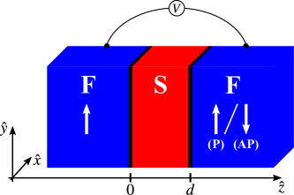
We consider a biased ballistic F/S/F junction grown along the crystallographic direction, in which the two semi-infinite ferromagnetic electrodes (F) are separated from the superconducting link (S) by ultrathin semiconducting tunneling barriers (see Fig. 1) with symmetry.
We model our system by means of its stationary Bogoliubov–de Gennes Hamiltonian De Gennes (1989)
| (1) |
where
| (2) |
represents the Hamiltonian of single electrons and its holelike counterpart ( and indicate the identity and the th Pauli matrix; is the vector of Pauli matrices). Both ferromagnetic electrodes are described within the Stoner model with the same exchange energy , and the, in general, different in-plane magnetization directions in the left and in the right F; the angles and are thereby measured with respect to the reference axis, which is taken to be the principal-symmetry [110] crystallographic axis.
Following earlier studies de Jong and Beenakker (1995); Žutić and Valls (1999, 2000); Costa et al. (2017, 2018, 2019); Costa and Fabian (2020), the ultrathin semiconducting interface layers are included into our model as deltalike barriers with heights (widths) () at the left and () at the right interface, respectively. Their SOCs enter through the effective spin-orbit fields and , where the terms scaling with the effective SOC strength () account for the Rashba SOC at the left (right) interface and the remaining ones for linearized Dresselhaus SOC with the effective strengths (). Note that we define the sign of opposite to that of , reflecting the fact that Rashba coupling arises from interfacial hybridization.
Inside the superconducting link, the -wave pairing potential
| (3) |
with the isotropic zero-temperature superconducting energy gap , couples the Bogoliubov–de Gennes Hamiltonian’s electron and hole blocks. To simplify the analytical description of our system, we take the same Fermi levels and effective carrier masses in all junction regions, and approximate the superconducting pairing potential by a Heaviside step function being nonzero only inside the superconductor and instantly jumping to zero inside the ferromagnets. All other spatial variations of the superconducting order parameter, i.e., its more realistic exponential decay in the vicinity of the F/S boundaries, are fully neglected and would need to be determined from a self-consistent formulation Halterman and Valls (2001). However, earlier experimental studies Baladié et al. (2001); Geers et al. (2001) demonstrated that even in F/S/F junctions in which the superconducting link is much thicker than the Bardeen–Cooper–Schrieffer coherence length, the current flows still quite uniformly, suggesting that spatial variations of the superconducting order parameter mostly average out and a self-consistent treatment is not necessary to understand such junctions’ generic transport features.
Assuming translational invariance parallel to the semiconducting interfaces, the solutions of the Bogoliubov–de Gennes equation
| (4) |
factorize into
| (5) |
where () refers to the in-plane momentum (position) vector and to the Bogoliubov–de Gennes equation’s most general solution for the effectively one-dimensional scattering problem along . Considering an incoming spin- electron from the left ferromagnet [ for spin up (spin down), which effectively indicates a spin parallel (antiparallel) to ], the latter is found to read as
| (6) |
in the left ferromagnet (),
| (7) |
in the superconducting link (), and accordingly
| (8) |
in the right ferromagnet (). The -projected wave vectors of spin- electrons and holes in the ferromagnets are given by
| (9) | ||||
| and | ||||
| (10) | ||||
respectively, whereas we obtain
| (11) | ||||
| and | ||||
| (12) | ||||
for electronlike and holelike quasiparticles inside the superconducting link; denotes the Fermi wave vector. Finally, the Bardeen–Cooper–Schrieffer coherence factors can be written as
| (13) | ||||
| as well as | ||||
| (14) | ||||
The given states account for all scattering processes that incident electrons may undergo at the semiconductor interfaces, including also the possibility of spin-flip scattering caused by the interfacial SOCs. Apart from spin-conserving and spin-flip specular (normal) reflections (with amplitudes and ), we need to pay special attention to spin-conserving (“conventional”) and spin-flip (“unconventional”) Andreev reflections (with amplitudes and ), which usually induce superconducting order in the ferromagnetic electrodes through proximity and lead thereby to numerous unique physical characteristics in superconducting magnetic junctions. Regarding transmissions (tunnelings) into the right ferromagnet, we need to distinguish between electron transmissions (with amplitudes and ) on the one hand and hole transmissions (with amplitudes and ) on the other.
To determine the unknown scattering amplitudes, we apply the interfacial boundary conditions (at and )
| (15) |
| (16) |
as well as
| (17) |
to the scattering states and numerically solve the resulting linear system of equations (at a given spin ; and abbreviates the zero matrix).
Assuring charge conservation 222Note that one needs to be careful when evaluating electrical currents from the Blonder–Tinkham–Klapwijk approach in junctions with more than two different regions to ensure that the calculated current is indeed conserved; see the thorough discussion in Ref. Dong et al. (2003). , and taking both the electron and hole contributions into account Lambert (1991); Božović and Radović (2002); *Bozovic2005; Yamashita et al. (2003); Dong et al. (2003), the tunneling conductance at zero temperature and bias voltage can be evaluated from
| (18) |
where indicates the contact cross-section area, is the positive elementary charge, corresponds to Planck’s constant, and taking the real parts () of the wave-vector ratios ensures that only the contributions originating from propagating states are included in the conductance calculation. Interestingly, the tunneling conductance of superconducting F/S/F junctions is therefore not only governed by the usual tunneling electrons (electron transmissions)—as is the case in normal-state F/N/F junctions according to Jullière’s model Jullière (1975)—but moreover impacted by the crucial Andreev-reflection process, which additionally transfers electrons in terms of supercurrent-carrying Cooper pairs across the superconducting junction link and will most likely give rise to unforeseen physical phenomena.
III General conductance features and signatures of induced triplet pairing
To analyze the most fundamental features and tunability of the tunneling conductance, we numerically evaluate Eq. (18) for realistic junction parameters. More specifically, we assume that both semiconducting tunneling barriers introduce the same weak potential scattering described by the dimensionless Blonder–Tinkham–Klapwijk parameters Blonder et al. (1982) , which would correspond, for example, to barrier heights and widths (substituting the typical Fermi wave vector of iron Martínez et al. (2020) and approximating the effective carrier mass by the free-electron mass). These barriers mimic reduced interfacial transparencies that could stem, e.g., from scattering due to imperfect interfaces or strongly differing Fermi levels (electron densities) in the ferromagnetic and superconducting junction regions Žutić and Valls (2000). The strengths of the interfacial Rashba and Dresselhaus SOCs are quantified by the dimensionless measures , , , and . For simplicity, we assume that both semiconducting interfaces are identical, i.e., they are characterized by the same Rashba and Dresselhaus SOC parameters, respectively. Rashba (Dresselhaus) parameters of () correspond then to bare Rashba (Dresselhaus) SOCs of (, connecting and with the barriers’ cubic Dresselhaus parameters and that are typically given in the literature Fabian et al. (2007); Matos-Abiague and Fabian (2009)). Recall that a thick MgO barrier was found to induce Rashba SOCs up to in Fe/MgO/V junctions Martínez et al. (2020), while AlP barriers of the given heights and widths would indeed raise Dresselhaus SOCs of . Finally, the spin polarization of the (identical) ferromagnets is determined by the dimensionless variable . The Fermi level is typically much larger than the superconducting gap and the excitation energies , motivating as a reasonable assumption for our calculations. All tunneling-conductance values discussed throughout this paper are normalized to the respective normal-state conductance of an ideal (perfectly transparent) N/N/N junction.
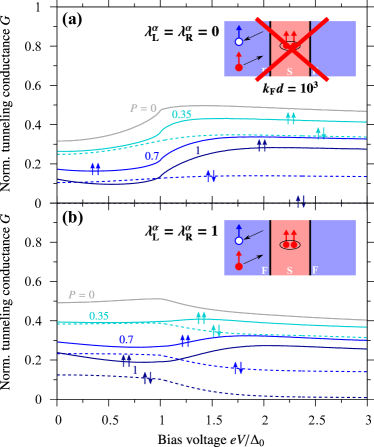
Figure 2 illustrates the tunneling conductance of a F/S/F junction comprising a “thin” superconducting link of thickness ( if ) once in the absence of interfacial SOCs and once if the moderate Rashba SOCs are present. In both cases, we consecutively increase the ferromagnets’ spin polarization from (N/S/N junction; gray color) to (half-metallic F/S/half-metallic F; dark-blue color), and distinguish parallel (both magnetizations point along ) from antiparallel (the left ferromagnet’s magnetization points along and the right one’s along ) magnetizations.
Let us first focus on the situation without interfacial SOCs [see Fig. 2(a)], in which spin-flip scatterings—i.e., also the crucial unconventional Andreev reflections—are completely forbidden, and all electrical transport is governed by electron transmissions (hole transmissions are negligible) and conventional Andreev reflections. However, as the superconducting link is rather thin when compared to usual superconducting coherence lengths (in the micron range Kittel (1996)), also conventional Andreev reflections are heavily suppressed—particularly at large spin polarizations, at which the through conventional Andreev reflections proximity-induced superconducting order inside the ferromagnets becomes negligibly tiny anyway due to these metals’ small coherence lengths Yang et al. (2005). As a consequence, thin superconducting links act mostly like rectangular potential barriers of height and width . Since , even subgap-energy electrons () can tunnel across the superconducting link with considerably large probabilities, entailing nonzero subgap tunneling conductances. Nevertheless, electron transmissions happen of course much more likely at energies above the barrier height (at ), explaining the enhanced tunneling conductances there. Increasing the ferromagnets’ spin polarization monotonically decreases the tunneling-conductance amplitudes, as less minority-spin electrons are then involved in tunneling and can contribute to transport. According to Jullière’s model Jullière (1975), switching the relative magnetization orientations from the parallel to their antiparallel configuration (at ) notably damps the probability for electron transmissions and thereby the tunneling conductance—most extreme in the half-metallic case in which no electrons can tunnel between oppositely magnetized ferromagnets and huge MR ratios are expected.
Second, we explore the effects associated with interfacial Rashba SOCs [see Fig. 2(b)]. Although conventional Andreev reflections are still strongly suppressed, the tunneling conductances in the subgap bias-voltage regime are remarkably enhanced by the present SOCs. This enhancement stems from the now additionally possible unconventional Andreev reflections 333The tunneling-conductance enhancement in the case of N/S/N junctions (i.e., at ) cannot be attributed to unconventional Andreev reflections, which become most pronounced in ferromagnetic junctions. Instead, the Rashba SOC terms in the single-particle Hamiltonian [recall Eq. (2)] always partially compensate the potential barrier (for appropriate and ), and lead thus to more electron transmissions and thereby a larger tunneling conductance. This can cause a conductance enhancement even in N/S/N junctions although unconventional Andreev reflections are strongly suppressed there., which are known to induce sizable superconducting triplet pairings even in strongly spin-polarized ferromagnets (and even though the superconducting link in our case is quite thin). The unconventional Andreev-reflection contributions become maximal in magnitude close to the chosen Rashba SOC strengths (but are still slightly smaller than the electron-transmission parts), can cause finite (subgap) tunneling conductances even in the case of half-metallic ferromagnetic electrodes, and are only merely affected by flipping the ferromagnets’ relative magnetization orientations—giving reasoning for the smaller (compared to the case without SOCs) absolute conductance changes when switching between parallel and antiparallel configurations (see our discussions in Sec. V). Increasing the bias voltage to values above the superconducting gap (), unconventional Andreev reflections become more unlikely and we essentially recover the purely by electron transmissions dominated transport regime at . However, we wish to stress that the interfacial SOCs furthermore act like additional deltalike potential barriers to electron transmissions [recall the Hamiltonian in Eq. (2)], eventually leading to even smaller (normal-state) tunneling conductances than in the absence of SOCs.

Next, we investigate the tunneling conductance of a F/S/F junction that contains a “thick” superconducting link of thickness ( if ); see Fig. 3. Such junctions are probably of much greater relevance to future experimental studies since their thicker superconducting regions inherently entail much larger Andreev-reflection probabilities and their conductance spectra simultaneously reveal the superconductor’s most fundamental spectroscopic fingerprints (gap).
We start again analyzing the case without interfacial SOCs [see Fig. 3(a)]. In fact, electron transmissions are now completely forbidden at and the subgap tunneling conductance is fully describable through the properties of conventional Andreev reflections (implicitly also carrying all necessary information about specular reflections if nonzero potential barriers are present). As we mentioned before, Andreev reflections are only merely affected by switching the ferromagnets’ relative magnetization orientations. Therefore, the subgap conductances for parallel and antiparallel magnetizations are (nearly) equal in magnitude as long as the tunneling conductance is fully dominated by Andreev reflections.
At the superconducting gap edge (), the tunneling conductance of a nonmagnetic N/S/N junction always reflects a sharp conductance peak, which indicates the superconductor’s density-of-states coherence peak and from which the superconducting energy gap can be estimated through transport experiments. With increasing spin polarization in a ferromagnetic junction, the conductance peak flattens and its position moves to energies slightly above the gap—though one can still quite reliably estimate the value of the superconducting gap from the peak position. Above the gap (), the tunneling conductance reveals unique oscillations, which are damped out with increasing voltage and finally disappear when approaching the normal-state transport regime at . These oscillations reflect the coherency of electrical transport through F/S/F junctions’ superconducting links. Coherent interference of incoming and outgoing quasiparticles (that underwent multiple reflections at the S/F interfaces) basically leads to Andreev-reflection and electron-transmission probabilities that strongly oscillate as functions of the excitation energy and the link thickness ; for the latter reason, the oscillations are usually referred to as geometrical oscillations.
An earlier work Božović and Radović (2002); *Bozovic2005 concluded that Andreev reflections are strongly suppressed and coherent electron transmissions become concurrently most likely whenever
| (19) |
where is an integer and, for simplicity, the effects of tunneling barriers (and large spin polarizations) were neglected. Inspecting our numerical results shows indeed that finite-height tunneling barriers and (large) spin polarizations only barely impact the conductance oscillations. Similar oscillations would actually be expected to likewise occur in junctions with thinner superconducting links, but the oscillation period is so large there (owing to the much smaller ) that we did not resolve them within the bias-voltage range chosen in Fig. 2. Regarding the tunneling-conductance amplitudes, increasing spin polarization decreases both the Andreev-reflection and electron-transmission contributions, and thereby suppresses the conductance. In the half-metallic case, the subgap conductance vanishes now even in the parallel magnetization configuration since all subgap transport is governed by conventional Andreev reflections, which are no longer possible if only majority-spin electrons are available.
Finite Rashba SOCs at the semiconducting interfaces additionally allow for the crucial unconventional Andreev reflections. While the general conductance features far below and far above the superconducting gap are the same as we thoroughly discussed earlier—including the conductance increase in the subgap region, the conductance decrease at , finite tunneling conductances in the half-metallic limit, and the geometrical oscillations at —the most puzzling feature arises in the vicinity of the gap edge itself. Increasing the ferromagnets’ spin polarization splits the conductance peak that we attributed to the gap-edge density-of-states coherence peak into two distinct peaks—one located below and the other above the gap energy . This peak splitting becomes most pronounced as the spin polarization approaches the half-metallic limit () and the unconventional Andreev-reflection conductance contribution becomes considerably large when compared to conventional Andreev reflections and electron transmissions. The latter observation might serve as a hint that the conductance-peak splitting and the peculiar unconventional Andreev-reflection process must be intimately connected.
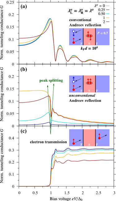
To resolve this connection, Fig. 4 illustrates the individual conductance contributions originating from conventional Andreev reflections, unconventional Andreev reflections, and electron transmissions. For brevity, we just discuss the case of parallel magnetizations (antiparallel magnetizations cause similar physics, but of course different conductance amplitudes) and focus on the representative spin polarization of iron electrodes, varying now instead the Rashba SOC strengths. Note that the conventional Andreev-reflection and electron-transmission parts clearly reflect the aforementioned geometrical oscillations with mutually suppressed (enhanced) Andreev-reflection (electron-transmission) probabilities at . The physics becomes nevertheless most interesting close to the gap edge. While conventional Andreev reflections still cause dominant conductance maxima (“peaks”) at —slightly sharpened and shifted with increasing Rashba SOCs—it is indeed the unconventional Andreev-reflection process that manifests itself in terms of split conductance double peaks located at energies slightly below and above . This peak splitting becomes again most clearly visible when unconventional Andreev reflection dominates subgap transport (i.e., close to ; recall that the same happened at large spin polarizations). Similarly to conventional Andreev reflections, which microscopically induce superconducting singlet correlations into the ferromagnets close to the interfaces, unconventional Andreev reflections introduce spin-polarized triplet correlations. As a consequence, the gap-edge density-of-states coherence peak splits into two peaks corresponding to and , accordingly; () indicates the superconducting gap due to singlet (triplet) pairing; note, however, that the triplet gap is small when compared to its singlet counterpart, as triplet pairing is in our case only induced through the interfacial SOCs (i.e., ). Measuring the junction’s tunneling conductance probes therefore directly the competing mixture of singlet and triplet correlations at the same time, and detects gap-edge conductance double peaks as an indirect signature of superconducting triplet pairings, which might help to identify the dominant pairing mechanism in upcoming transport studies.
IV Magnetic tunability of conductance features
Apart from the enhancement of the subgap conductance and the coherence-peak (conductance-peak) splitting, interfacial SOC gives typically rise to unique transport magnetoanisotropies, i.e., rotating the magnetization direction of (at least) one ferromagnet considerably alters the conductance amplitudes in the presence of interfacial SOCs. While out-of-plane magnetization rotations (in a plane perpendicular to the semiconducting barriers) already cause magnetoanisotropic conductances if the barriers induce either Rashba or Dresselhaus SOCs, in-plane magnetoanisotropies require interfering Rashba and Dresselhaus SOCs. As out-of-plane magnetization directions are not realistic in spin-valve MR geometries, we focus on the in-plane case.
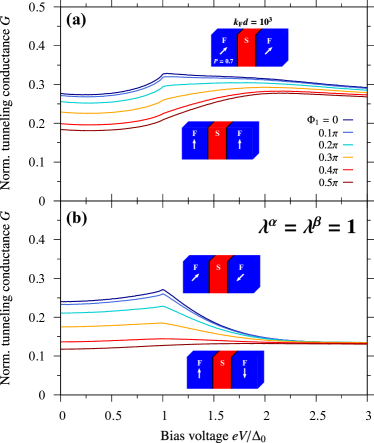
Figure 5 shows the tunneling conductance of a F/S/F junction with a “thin” superconducting link () considering the moderate (and equal in magnitude) Rashba and Dresselhaus SOCs and rotating the magnetization (once in the parallel and once in the antiparallel configuration) from the - to the -direction (from to ). Equal Rashba and Dresselhaus parameters are chosen since the interference of the Rashba and Dresselhaus spin-orbit fields leads then to the effective spin-orbit fields
| (20) | ||||
| and | ||||
| (21) | ||||
Tunneling electrons are therefore subject to the maximal SOCs if the magnetizations are aligned along (due to the dependence) and do not at all experience any SOC for magnetizations parallel to (as the dependence dropped out), eventually raising the maximally possible magnetoanisotropy.
As a result, the additionally generated unconventional Andreev-reflection conductance contribution becomes maximal at and completely vanishes at , explaining the overall substantial conductance decrease when increasing from to . Recall that conventional Andreev reflections are suppressed in junctions with “thin” superconducting links and the tunneling conductance is, apart from partially through SOCs allowed unconventional Andreev reflections, largely determined by electron transmissions. Surprisingly, and in sharp contrast to two-electrode F/S junctions in which they even fully disappear there Högl et al. (2015); *Hoegl2015a, unconventional Andreev reflections (at ) are most likely at energies around the gap edge (), facilitating a somewhat broadened conductance peak (“conductance shoulder”). As before, the tunneling conductance at energies well above mostly stems from electron transmissions, and just slightly decreases with increasing owing to the effectively slightly lowered tunneling probability.
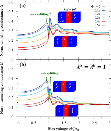
Analogously, we present the tunneling conductance’s magnetization-angle dependence for a F/S/F junction containing a “thick” superconducting link () in Fig. 6; all other parameters are not changed. As we argued above, the unconventional Andreev-reflection conductance contribution gets maximal at and vanishes at . Besides remarkably enhancing the subgap tunneling conductance, the superconducting triplet pairings induced by unconventional Andreev reflections split the gap-edge conductance peak again into two distinct peaks. Just as we encountered when analyzing this feature earlier, the peak splitting becomes most pronounced when simultaneously the unconventional Andreev-reflection process dominates the subgap tunneling conductance, i.e., at in our case. Note that the split conductance peaks’ amplitude ratios in the parallel and antiparallel magnetization configurations are opposite, as one might also observe in Fig. 3(b). While the peak slightly above the gap corresponds to the larger tunneling conductance for parallel magnetizations—as the tunneling conductance gets there amplified by additionally allowed electron transmissions—it is the peak below the gap that entails maximal tunneling conductances in the antiparallel magnetized scenario. Finally, the aforementioned geometrical oscillations at are clearly visible and not notably altered by rotating the magnetization orientations, while the conductance amplitudes decrease slightly with increasing there due to the slightly reduced interfacial transparencies, just as we explained for “thin” superconducting links above.
While Andreev reflections are only barely impacted by switching the ferromagnets’ relative magnetizations from the parallel to the antiparallel orientations (recall our discussions in Sec. III), the last paragraphs demonstrated that they are nonetheless extremely sensitive to rotations of the ferromagnets’ absolute magnetization directions in the presence of interfacial SOCs, and marked magnetoanisotropies in the tunneling conductance can occur. To quantify the latter, and emphasize that they predominantly originate from the strongly magnetoanisotropic (unconventional) Andreev-reflection probabilities, an earlier work on two-electrode F/S junctions established the in-plane magnetoanisotropic Andreev reflection (MAAR) Högl et al. (2015); *Hoegl2015a
| (22) |
One could evaluate the MAAR, for instance, deep inside the superconducting junction regime at , and compare the values against its normal-state counterpart at . As we can already expect from the large magnetization-controlled tunability of the absolute conductance amplitudes in Figs. 5 and 6, unconventional Andreev reflections could entail huge superconducting MAAR ratios, which can easily exceed the equivalent normal-state tunneling anisotropic magnetoresistance Moser et al. (2007); Matos-Abiague and Fabian (2009) by more than three orders of magnitude in the half-metallic limit and can be further enhanced by increasing the thickness of the superconducting link . While the calculated MAAR in a junction with a “thin” superconducting link () lies clearly below the values predicted for comparable two-electrode F/S junctions (as Andreev reflection is not the dominant scattering process there), “thick” superconducting links () cause MAARs that already remarkably overcome those in the corresponding F/S junctions (as Andreev reflection dominates now the subgap regime). As the overall physics and qualitative characteristics are basically similar to the F/S case, we do not deeply analyze our MAAR calculations here.
V Magnetoresistance effects
MR effects count to the probably most intensively investigated phenomena in magnetic spin-valve junctions. Our work offers the possibility to study the MR of superconducting magnetic spin valves, and elaborate more on the ramifications of the competition between the usual—and in normal-state spin valves dominant—electron transmissions and the superconducting junctions’ unique Andreev reflections. Adapting its most common definition, the MR ratio at an absolute magnetization orientation determined by (in the left ferromagnet) is given by
| (23) |
where [] indicates the tunneling conductance in the parallel (antiparallel) magnetization configurations and can be extracted from Eq. (18) at zero temperature.
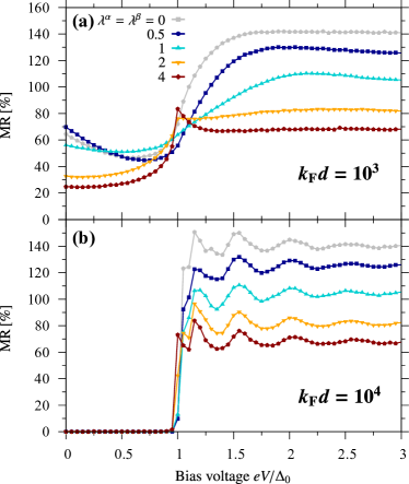
In Fig. 7, we illustrate the computed MR [more precisely, ] as a function of the applied bias voltage for various strengths of interfacial Rashba and Dresselhaus SOCs , distinguishing again between junctions with “thin” () and “thick” () superconducting links. As expected from our earlier analyses of the conductance features, the MR ratios always reach their maximal values whenever the underlying tunneling conductance is dominated by electron transmissions, i.e., at . In the subgap bias-voltage regime, even small conductance contributions originating from conventional and—in the presence of nonzero interfacial SOCs—unconventional Andreev reflections immediately lower the resulting MR. This observation explains the MR suppression with increasing SOC strength in the junction with the “thin” link, as well as the fully vanishing subgap MR for the “thick” link. In the first case (“thin” link), increasing the SOC parameters above raises a marked conductance enhancement owing to unconventional Andreev reflections. Since Andreev reflections are much less sensitive to changes of the relative magnetization orientations than the in the absence of SOCs dominant electron transmissions, the related MR starts to be remarkably damped, finally resulting in a complete suppression if the conductance is exclusively determined by (unconventional) Andreev reflections as we witness in the second case (“thick” link). At voltages above the gap (), the MR mostly reveals the conductance properties resulting from usual electron transmissions, including its monotonic decrease with increasing SOC strengths; the interfacial SOCs act then similarly to additional interfacial barriers that suppress electron transmissions and thus the MR. Interestingly, the geometrical conductance oscillations caused by coherent electron transmissions through “thick” superconducting links are moreover transferred into the respective MR–bias voltage characteristics. Note that the MRs in the junctions’ normal-state counterparts (recovered at ) are—analogously to the related tunneling conductances (compare, e.g., Fig. 2 to Fig. 3 supposing )—nearly completely independent of the link thickness, which is a consequence of our fully ballistic description. Regarding the maximally possible MR amplitudes, half-metallic junctions (with spin polarizations ) are certainly the most auspicious candidates; similarly to normal-conducting systems, maximal MRs easily reach then values above .
Summarizing the preceding paragraphs, the MR features (amplitudes) are predominantly controlled by the intriguing competition between Andreev reflections (dominant in the subgap regime, ) and electron transmissions (dominant at ). Most relevant to future experimental studies might therefore be exploring the MR exactly at the gap-edge energy, i.e., at , at which the aforementioned competition between Andreev reflections and electron transmissions becomes most pronounced. We will address the experimental signatures in Sec. VI.
VI Anisotropic magnetoresistance
As we thoroughly discussed in Sec. IV, interfacial SOCs usually entail marked magnetoanisotropies in experimentally probeable transport quantities. Consequently, not only the tunneling conductance itself, but also closely related measures, like the MR, strongly depend on the absolute orientation of the ferromagnets’ magnetization directions. We emphasized that in Eq. (23) through explicitly stating the MR’s dependence. While the magnetoanisotropic MR—usually referred to as anisotropic magnetoresistance (AMR)—has already been comprehensively analyzed in normal-conducting F/N/F junctions Matos-Abiague and Fabian (2009), characterizations of AMR phenomena in superconducting junctions have yet been missing. To close this gap, we present the angular dependence of the considered F/S/F junction’s AMR [note that ; recall Eq. (23)] for various uniform SOC strengths in Fig. 8. Motivated by our previous arguments, we focus on the bias voltage , at which we expect a strong competition between Andreev reflections and electron transmissions, to compare the results in the superconducting to those in the normal-conducting () scenario; the thickness of the “thin” link is again and that of the “thick” link .
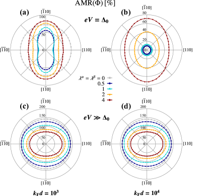
As long as interfacial SOCs are completely absent, the (A)MR is isotropic, and the MR amplitudes do hence not alter as the absolute direction of the ferromagnets’ magnetizations gets rotated (gray circles). Already weak SOCs, however, notably tilt the AMR curves (more elliptical, colored, curves), and give rise to clearly magnetoanisotropic MRs, with substantially larger MR ratios at magnetizations pointing along (as unconventional Andreev reflections get suppressed there and electron transmissions dominate). Although qualitatively similar physics occurs in the normal state, the “tilting” (which is directly linked to the “strength” of the MR magnetoanisotropy, as we will elaborate on later) is much weaker than in the superconducting case (whereas the overall MR values are more than twice as large as in the superconducting junction due to the dominant electron transmissions in normal-state junctions) and it is now the magnetization along that results in (slightly) larger MR amplitudes.
These observations suggest that, while overall large MR ratios indicate dominant electron transmissions, marked AMR magnetoanisotropies serve as an experimentally accessible signature of dominant Andreev reflections. These contrary features could be beneficial to subsequent experimental works to disentangle Andreev-reflection- from electron-transmission-related physics. As they both predominantly originate from the peculiar Andreev-reflection process, MAAR and AMR effects share all their fundamental properties. For instance, and similarly to the aforementioned in-plane MAAR, it is vital to the AMR that interfacial Rashba and Dresselhaus SOCs interfere. If just Rashba or Dresselhaus SOCs alone were present, the (A)MR would become fully isotropic. Maximally anisotropic AMRs arise again if the Rashba and Dresselhaus SOC strengths are equal, as we likewise explained in connection with the tunneling-conductance magnetoanisotropies in Sec. IV.
To quantify the “strength” of the MR magnetoanisotropy, and relate it to the “tilting” of the AMR curves visible in Fig. 8, we introduce the AMR efficiency Matos-Abiague and Fabian (2009)
| (24) |
which essentially measures the relative change of the MR ratios while the ferromagnets’ magnetizations are rotated from the - toward the -orientation.
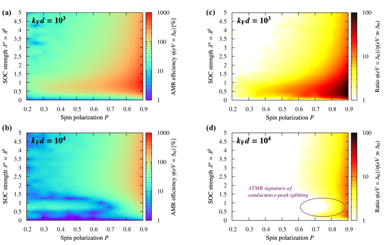
Figure 9 shows the computed AMR efficiencies as functions of the ferromagnets’ spin polarization and the uniform SOC strengths , as well as the ratio between the AMR efficiencies in the superconducting and normal-conducting states, respectively. The results further substantiate our previous claims, and demonstrate the peculiar role of unconventional Andreev reflections for another time. More specifically, the MR magnetoanisotropies of junctions containing the “thin” superconducting link become most pronounced (resulting in the largest AMR efficiencies ) as the ferromagnets’ spin polarization approaches the half-metallic limit () and the SOC strengths are tuned to . As we pointed out in Sec. III, those parameters maximize the unconventional Andreev-reflection contribution to the tunneling conductances (at the considered bias voltage ), which responds most sensitively to changes of the absolute magnetization directions and entails huge MR magnetoanisotropies (). Noteworthy, the AMR efficiency in the superconducting state exceeds its normal-state counterpart by more than two orders of magnitude.
The arguments provided in the preceding paragraph do, in principle, also hold for junctions with the “thick” superconducting link. Nevertheless, the MR magnetoanisotropies (amplitudes of ) appear to be substantially lower in that case, which must indicate that unconventional Andreev reflections are additionally suppressed. We indeed observe this suppression most clearly at spin polarization and SOC parameters , for which we analyzed the underlying tunneling conductances in all details in Sec. III unraveling the conductance-peak splitting at as a transport signature of superconducting triplet pairings. As a result, the initially present conductance peak exactly at turns into a conductance dip, the unconventional Andreev-reflection contribution gets damped, and the calculated MR magnetoanisotropy () must therefore notably drop. The huge MR magnetoanisotropies () would instead occur slightly below and above the superconducting gap, corresponding to the two newly forming conductance double peaks. The latter can hence not only be identified in the tunneling-conductance data, but leave also an indirect imprint on the AMR characteristics. Though the unconventional Andreev-reflection contribution at is small(er), it is large enough to raise AMR efficiencies that still overcome their normal-state counterparts by more than one order of magnitude.
VII Conclusions
To summarize, we studied the tunneling-conductance features of superconducting magnetic F/S/F spin-valve junctions paying special attention to the ramifications of interfacial Rashba and Dresselhaus SOCs. We distinguished between junctions hosting “thin” (thickness of about ) and “thick” (thickness of about ) superconducting links, and allowed for arbitrary in-plane orientations of the magnetization directions inside the ferromagnetic electrodes. Interfacial SOCs facilitate unconventional (spin-flip) Andreev reflections at junction interfaces that are commonly expected to be at the heart of numerous transport anomalies, as they concurrently introduce spin-polarized superconducting triplet pairings into the system. Regarding the considered F/S/F junctions, we observed that unconventional Andreev reflections can give rise to a conductance-peak splitting close to the singlet-gap energy, which eventually reveals the interplay between the usual superconducting singlet and the additional effectively induced triplet gaps. Owing to their close connection to unconventional Andreev reflections, we demonstrated that these peak splittings—and at the same time also the overall amplitudes of the tunneling conductance—are efficiently tunable through altering the ferromagnets’ absolute magnetization orientations. We eventually quantified the MR of superconducting spin-valve junctions, and unraveled that unconventional Andreev reflections (and thus indirectly the present SOCs) furthermore lead to marked MR magnetoanisotropies, which we termed AMRs. Measuring the AMR efficiency (i.e., the “strength” of the MR magnetoanisotropy) provides another experimental possibility to detect the triplet-pairing signifying gap-edge conductance double peaks. In view of future experiments, we suggest focusing on highly spin-polarized junctions, in which the strong spin filtering of transmitted electrons yields overall giant MRs (analogously to Jullière’s model), but which still entail a considerable amount of unconventional Andreev reflections to simultaneously raise huge magnetoanisotropies (MAARs and AMRs).
Acknowledgements.
This work was supported by Deutsche Forschungsgemeinschaft (DFG, German Research Foundation) through Subproject B07 within the Collaborative Research Center SFB 1277 (Project-ID 314695032) and the Research Grant “Spin and magnetic properties of superconducting tunnel junctions” (Project-ID 454646522).References
- Jullière (1975) M. Jullière, Phys. Lett. 54A, 225 (1975).
- Moodera et al. (1995) J. S. Moodera, L. R. Kinder, T. M. Wong, and R. Meservey, Phys. Rev. Lett. 74, 3273 (1995).
- Žutić et al. (2004) I. Žutić, J. Fabian, and S. Das Sarma, Rev. Mod. Phys. 76, 323 (2004).
- Fabian et al. (2007) J. Fabian, A. Matos-Abiague, C. Ertler, P. Stano, and I. Žutić, Acta Phys. Slovaca 57, 565 (2007).
- Fert (2008) A. Fert, Thin Solid Films 517, 2 (2008).
- Hirota et al. (2002) E. Hirota, H. Sakakima, and K. Inomata, Giant Magneto-Resistance Devices, Springer Series in Surface Sciences, Vol. 40 (Springer-Verlag, Berlin, Heidelberg, 2002).
- Parkin (2002) S. S. P. Parkin, “Applications of magnetic nanostructures,” in Spin Dependent Transport in Magnetic Nanostructures, edited by S. Maekawa and T. Shinjo (Taylor and Francis, 2002) pp. 237–271.
- Slaughter et al. (2003) J. M. Slaughter, M. DeHerrera, and H. Dürr, “Magnetoresistive RAM,” in Nanoelectronics and Information Technology, edited by R. Waser (Wiley-VCH and Co. KGaA, 2003) pp. 591–606.
- Bhatti et al. (2017) S. Bhatti, R. Sbiaa, A. Hirohata, H. Ohno, S. Fukami, and S. Piramanayagam, Mater. Today 20, 530 (2017).
- Ioffe et al. (1999) L. B. Ioffe, V. B. Geshkenbein, M. V. Feigel’man, A. L. Fauchère, and G. Blatter, Nature (London) 398, 679 (1999).
- Mooij et al. (1999) J. E. Mooij, T. P. Orlando, L. Levitov, L. Tian, C. H. van der Wal, and S. Lloyd, Science 285, 1036 (1999).
- Blatter et al. (2001) G. Blatter, V. B. Geshkenbein, and L. B. Ioffe, Phys. Rev. B 63, 174511 (2001).
- Ustinov and Kaplunenko (2003) A. V. Ustinov and V. K. Kaplunenko, J. Appl. Phys. 94, 5405 (2003).
- Yamashita et al. (2005) T. Yamashita, K. Tanikawa, S. Takahashi, and S. Maekawa, Phys. Rev. Lett. 95, 097001 (2005).
- Feofanov et al. (2010) A. K. Feofanov, V. A. Oboznov, V. V. Bol’ginov, J. Lisenfeld, S. Poletto, V. V. Ryazanov, A. N. Rossolenko, M. Khabipov, D. Balashov, A. B. Zorin, P. N. Dmitriev, V. P. Koshelets, and A. V. Ustinov, Nat. Phys. 6, 593 (2010).
- Khabipov et al. (2010) M. I. Khabipov, D. V. Balashov, F. Maibaum, A. B. Zorin, V. A. Oboznov, V. V. Bolginov, A. N. Rossolenko, and V. V. Ryazanov, Supercond. Sci. Technol. 23, 045032 (2010).
- Devoret and Schoelkopf (2013) M. H. Devoret and R. J. Schoelkopf, Science 339, 1169 (2013).
- Eschrig (2011) M. Eschrig, Phys. Today 64, 43 (2011).
- Linder and Robinson (2015) J. Linder and J. W. A. Robinson, Sci. Rep. 5, 15483 (2015).
- Soulen Jr. (1998) R. J. Soulen Jr., Science 282, 85 (1998).
- Soulen Jr. et al. (1999) R. J. Soulen Jr., M. S. Osofsky, B. Nadgorny, T. Ambrose, P. Broussard, S. F. Cheng, J. Byers, C. T. Tanaka, J. Nowack, J. S. Moodera, G. Laprade, A. Barry, and M. D. Coey, J. Appl. Phys. 85, 4589 (1999).
- Bulaevskii et al. (1977) L. N. Bulaevskii, V. V. Kuzii, and A. A. Sobyanin, Pis’ma Zh. Eksp. Teor. Fiz. 25, 314 (1977).
- Bul (1977) JETP Lett. 25, 290 (1977).
- Ryazanov et al. (2001) V. V. Ryazanov, V. A. Oboznov, A. Y. Rusanov, A. V. Veretennikov, A. A. Golubov, and J. Aarts, Phys. Rev. Lett. 86, 2427 (2001).
- Högl et al. (2015) P. Högl, A. Matos-Abiague, I. Žutić, and J. Fabian, Phys. Rev. Lett. 115, 116601 (2015).
- Hoe (2015) Phys. Rev. Lett. 115, 159902(E) (2015).
- Jacobsen et al. (2016) S. H. Jacobsen, I. Kulagina, and J. Linder, Sci. Rep. 6, 23926 (2016).
- Costa et al. (2017) A. Costa, P. Högl, and J. Fabian, Phys. Rev. B 95, 024514 (2017).
- Martínez et al. (2020) I. Martínez, P. Högl, C. González-Ruano, J. P. Cascales, C. Tiusan, Y. Lu, M. Hehn, A. Matos-Abiague, J. Fabian, I. Žutić, and F. G. Aliev, Phys. Rev. Appl. 13, 014030 (2020).
- Nilsson et al. (2008) J. Nilsson, A. R. Akhmerov, and C. W. J. Beenakker, Phys. Rev. Lett. 101, 120403 (2008).
- Duckheim and Brouwer (2011) M. Duckheim and P. W. Brouwer, Phys. Rev. B 83, 054513 (2011).
- Lee et al. (2012) S.-P. Lee, J. Alicea, and G. Refael, Phys. Rev. Lett. 109, 126403 (2012).
- Nadj-Perge et al. (2014) S. Nadj-Perge, I. K. Drozdov, J. Li, H. Chen, S. Jeon, J. Seo, A. H. MacDonald, B. A. Bernevig, and A. Yazdani, Science 346, 602 (2014).
- Dumitrescu et al. (2015) E. Dumitrescu, B. Roberts, S. Tewari, J. D. Sau, and S. Das Sarma, Phys. Rev. B 91, 094505 (2015).
- Pawlak et al. (2016) R. Pawlak, M. Kisiel, J. Klinovaja, T. Meier, S. Kawai, T. Glatzel, D. Loss, and E. Meyer, npj Quantum Inf. 2, 16035 (2016).
- Ruby et al. (2017) M. Ruby, B. W. Heinrich, Y. Peng, F. von Oppen, and K. J. Franke, Nano Lett. 17, 4473 (2017).
- Livanas et al. (2019) G. Livanas, M. Sigrist, and G. Varelogiannis, Sci. Rep. 9, 6259 (2019).
- Manna et al. (2020) S. Manna, P. Wei, Y. Xie, K. T. Law, P. A. Lee, and J. S. Moodera, Proc. Natl. Acad. Sci. 117, 8775 (2020).
- Keizer et al. (2006) R. S. Keizer, S. T. B. Goennenwein, T. M. Klapwijk, G. Miao, G. Xiao, and A. Gupta, Nature (London) 439, 825 (2006).
- Bergeret et al. (2001a) F. S. Bergeret, A. F. Volkov, and K. B. Efetov, Phys. Rev. Lett. 86, 3140 (2001a).
- Bergeret et al. (2001b) F. S. Bergeret, A. F. Volkov, and K. B. Efetov, Phys. Rev. Lett. 86, 4096 (2001b).
- Bergeret et al. (2001c) F. S. Bergeret, A. F. Volkov, and K. B. Efetov, Phys. Rev. B 64, 134506 (2001c).
- Eschrig et al. (2003) M. Eschrig, J. Kopu, J. C. Cuevas, and G. Schön, Phys. Rev. Lett. 90, 137003 (2003).
- Houzet and Buzdin (2007) M. Houzet and A. I. Buzdin, Phys. Rev. B 76, 060504(R) (2007).
- Eschrig and Löfwander (2008) M. Eschrig and T. Löfwander, Nat. Phys. 4, 138 (2008).
- Grein et al. (2009) R. Grein, M. Eschrig, G. Metalidis, and G. Schön, Phys. Rev. Lett. 102, 227005 (2009).
- Khaire et al. (2010) T. S. Khaire, M. A. Khasawneh, W. P. Pratt Jr., and N. O. Birge, Phys. Rev. Lett. 104, 137002 (2010).
- Robinson et al. (2010a) J. W. A. Robinson, G. B. Halász, A. I. Buzdin, and M. G. Blamire, Phys. Rev. Lett. 104, 207001 (2010a).
- Robinson et al. (2010b) J. W. A. Robinson, J. D. S. Witt, and M. G. Blamire, Science 329, 59 (2010b).
- Banerjee et al. (2014) N. Banerjee, J. W. A. Robinson, and M. G. Blamire, Nat. Commun. 5, 4771 (2014).
- Diesch et al. (2018) S. Diesch, P. Machon, M. Wolz, C. Sürgers, D. Beckmann, W. Belzig, and E. Scheer, Nat. Commun. 9, 5248 (2018).
- Bergeret and Tokatly (2013) F. S. Bergeret and I. V. Tokatly, Phys. Rev. Lett. 110, 117003 (2013).
- Bergeret and Tokatly (2014) F. S. Bergeret and I. V. Tokatly, Phys. Rev. B 89, 134517 (2014).
- De Gennes (1966) P. G. De Gennes, Phys. Lett. 23, 10 (1966).
- Hauser (1969) J. J. Hauser, Phys. Rev. Lett. 23, 374 (1969).
- Li et al. (2013) B. Li, N. Roschewsky, B. A. Assaf, M. Eich, M. Epstein-Martin, D. Heiman, M. Münzenberg, and J. S. Moodera, Phys. Rev. Lett. 110, 097001 (2013).
- Andreev (1964) A. F. Andreev, Zh. Eksp. Teor. Fiz. 46, 1823 (1964).
- And (1964) J. Exp. Theor. Phys. 19, 1228 (1964).
- Božović and Radović (2002) M. Božović and Z. Radović, Phys. Rev. B 66, 134524 (2002).
- Boz (2005) Phys. Rev. B 71, 229901(E) (2005).
- Bychkov and Rashba (1984) Y. A. Bychkov and E. I. Rashba, Pis’ma Zh. Eksp. Teor. Fiz. 39, 66 (1984).
- Byc (1984) JETP Lett. 39, 78 (1984).
- Dresselhaus (1955) G. Dresselhaus, Phys. Rev. 100, 580 (1955).
- Blonder et al. (1982) G. E. Blonder, M. Tinkham, and T. M. Klapwijk, Phys. Rev. B 25, 4515 (1982).
- Moen and Valls (2017) E. Moen and O. T. Valls, Phys. Rev. B 95, 054503 (2017).
- Moen and Valls (2018a) E. Moen and O. T. Valls, Phys. Rev. B 97, 174506 (2018a).
- Moen and Valls (2018b) E. Moen and O. T. Valls, Phys. Rev. B 98, 104512 (2018b).
- Note (1) Strictly speaking, the term tunneling magnetoresistance (TMR) is only used for junctions in the tunneling limit, i.e., if strong interfacial tunneling barriers were present. As we consider weak barriers to elucidate the physics related to Andreev reflections, we shall rather call the effect simply magnetoresistance (MR).
- De Gennes (1989) P. G. De Gennes, Superconductivity of Metals and Alloys (Addison Wesley, Redwood City, 1989).
- de Jong and Beenakker (1995) M. J. M. de Jong and C. W. J. Beenakker, Phys. Rev. Lett. 74, 1657 (1995).
- Žutić and Valls (1999) I. Žutić and O. T. Valls, Phys. Rev. B 60, 6320 (1999).
- Žutić and Valls (2000) I. Žutić and O. T. Valls, Phys. Rev. B 61, 1555 (2000).
- Costa et al. (2018) A. Costa, J. Fabian, and D. Kochan, Phys. Rev. B 98, 134511 (2018).
- Costa et al. (2019) A. Costa, A. Matos-Abiague, and J. Fabian, Phys. Rev. B 100, 060507(R) (2019).
- Costa and Fabian (2020) A. Costa and J. Fabian, Phys. Rev. B 101, 104508 (2020).
- Halterman and Valls (2001) K. Halterman and O. T. Valls, Phys. Rev. B 65, 014509 (2001).
- Baladié et al. (2001) I. Baladié, A. Buzdin, N. Ryzhanova, and A. Vedyayev, Phys. Rev. B 63, 054518 (2001).
- Geers et al. (2001) J. M. E. Geers, M. B. S. Hesselberth, J. Aarts, and A. A. Golubov, Phys. Rev. B 64, 094506 (2001).
- Note (2) Note that one needs to be careful when evaluating electrical currents from the Blonder–Tinkham–Klapwijk approach in junctions with more than two different regions to ensure that the calculated current is indeed conserved; see the thorough discussion in Ref. Dong et al. (2003).
- Lambert (1991) C. J. Lambert, J. Phys.: Condens. Matter 3, 6579 (1991).
- Yamashita et al. (2003) T. Yamashita, H. Imamura, S. Takahashi, and S. Maekawa, Phys. Rev. B 67, 094515 (2003).
- Dong et al. (2003) Z. C. Dong, R. Shen, Z. M. Zheng, D. Y. Xing, and Z. D. Wang, Phys. Rev. B 67, 134515 (2003).
- Matos-Abiague and Fabian (2009) A. Matos-Abiague and J. Fabian, Phys. Rev. B 79, 155303 (2009).
- Kittel (1996) C. Kittel, Introduction to Solid State Physics (John Wiley & Sons, Ltd., 1996).
- Yang et al. (2005) L. Y. Yang, Z. M. Zheng, and D. Y. Xing, Eur. Phys. J. B 47, 479 (2005).
- Note (3) The tunneling-conductance enhancement in the case of N/S/N junctions (i.e., at ) cannot be attributed to unconventional Andreev reflections, which become most pronounced in ferromagnetic junctions. Instead, the Rashba SOC terms in the single-particle Hamiltonian [recall Eq. (2)] always partially compensate the potential barrier (for appropriate and ), and lead thus to more electron transmissions and thereby a larger tunneling conductance. This can cause a conductance enhancement even in N/S/N junctions although unconventional Andreev reflections are strongly suppressed there.
- Moser et al. (2007) J. Moser, A. Matos-Abiague, D. Schuh, W. Wegscheider, J. Fabian, and D. Weiss, Phys. Rev. Lett. 99, 056601 (2007).