[aff1]Physics Department, The University of Texas-Austin, Austin, Texas 78712, USA \affil[aff2]Institute of Radiation Physics, Helmholtz-Zentrum Dresden-Rossendorf, 01328 Dresden, Germany \affil[aff3]School of Applied and Engineering Physics, Cornell University, Ithaca, New York 14850, USA \affil[aff4]Technische Universität Dresden, 01062 Dresden, Germany \corresp[cor1]downer@physics.utexas.edu
Two-Pulse Direct Laser Acceleration in a Laser-Driven Plasma Accelerator
Abstract
We present methods and preliminary observations of two pulse Direct Laser Acceleration in a Laser-Driven Plasma Accelerator. This acceleration mechanism uses a second co-propagating laser pulse to overlap and further accelerate electrons in a wakefield bubble, increasing energy at the cost of emittance when compared to traditional laser wakefield acceleration (LWFA). To this end, we introduce a method of femtosecond scale control of time delay between two co-propagating pulses. We show energy enhancement when the separation between the two pulses approaches the bubble radius.
1 INTRODUCTION
Laser Wakefield Acceleration (LWFA) has progressed and diversified significantly since it was first proposed in Tajima and Dawson (1979). This technique has traditionally relied on the ponderomotive force from tightly focused and compressed laser pulses to drive fast plasma waves which then transfer energy to the injected electrons. These waves can support accelerating fields , where is the electron density, exceeding GV/cm Faure et al. (2006); Esarey, Schroeder, and Leemans (2009); Downer et al. (2018), several orders of magnitude larger than modern radio-frequency accelerators Behnke et al. (2013). The most common variation of this method is blowout or bubble regime LWFA where an ultrashort and high intensity, , laser pulse in a sub-critical density plasma drives a near spherical electron-depleted region with a nearly linear radial electric field Faure et al. (2004); Geddes et al. (2004); Mangles et al. (2004). A great deal of research has focused on manipulating the injection mechanism used to introduce these electrons into the acceleration process ranging from the Self-Injection used in the first blowout LWFAs, to Self-Truncated Ionization Injection Zeng et al. (2014); Couperus et al. (2017); Irman et al. (2018), to Shock Front Injection, Buck et al. (2013) to Trojan Horse Injection Deng et al. (2019), to Downramp Injection Schmid et al. (2010). However, work on controlling the evolving acceleration process has largely focused on implementing plasma channels Tsung et al. (2004); Leemans et al. (2006). We discuss the implementation of a secondary laser pulse to manipulate the electrons as they accelerate. In this proceeding, we demonstrate a method of femtosecond control of the timing between two co-propagating laser pulses.
The major benefits of implementing controllable direct laser acceleration (DLA) in an LWFA system are threefold. First, we can directly transfer energy from the DLA pulse to the accelerating electrons through a force coupled to their betatron oscillation. Second, we can increase the dephasing length of the accelerating electrons by adding transverse momentum, relativistically reducing their longitudinal velocity. Thirdly, we can directly impact the wiggler strength experienced by the electrons in the bubble. Among other advantages, this allows us to enhance the x-ray energy and flux of the resulting betatron radiation without the need to increase the number or energy of the accelerating electrons. In this proceeding, we will focus only on the energy transfer as it is a good first indicator of successful overlap between the DLA pulse and the accelerating electrons.
Some past works have examined the impact of direct laser acceleration from the tail of a drive pulse on an accelerating electron bunch through both simulation Shaw et al. (2016) and experiment Cipiccia et al. (2011); Shaw et al. (2018). In these studies, DLA was controlled by increasing the pulse length of the drive pulse, thereby increasing the amplitude of the pulse tail that interacted with the accelerating electron bunch. This experimental study is based on existing simulation and theory Zhang, Khudik, and Shvets (2015); Zhang et al. (2016, 2018); Wang et al. (2019). We seek to make the DLA process more controllable by using a second independent pulse to control electrons in a wake driven by the first pulse.
The motivation of this work is to develop an independent technique to enhance LWFA electron energy beyond the traditional dephasing limit. The enhanced-energy bunch could then drive a Plasma Wakefield Accelerator (PWFA) Litos et al. (2014); Martinez de la Ossa et al. (2019), while the betatron x-ray output is useful for imaging applications Kneip et al. (2011); Cole et al. (2015).
2 Experimental Methods
To separate a DLA pulse of desired energy and controlled delay from the LWFA drive pulse, we inserted a segmented flat circular mirror into the delivery line of the DRACO laser pulse at HZDR. A central circular portion of this mirror (radius cm) reflected the center of the DRACO Schramm et al. (2017) pulse, directing it toward the gas jet to drive a LWFA. The outer annulus of the segmented mirror reflected the remaining outer portion of the DRACO pulse, directing it also toward the gas jet to serve as a DLA pulse.
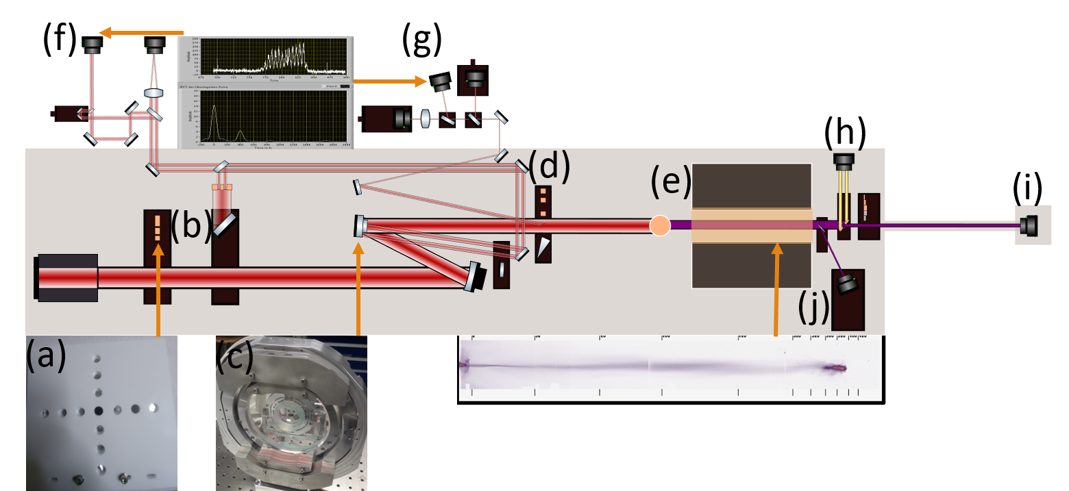
We utilized the experimental setup depicted in Fig. 1 in order to re-measure the added time delay added or removed by our segmented mirror and to check both beam profiles between shot groups. The delay tended to drift several femtoseconds in the negative direction over a group of shots. This was likely due to feedback created from radiation generated on shot. This behaviour was eliminated by implementing a remote switch to disconnect the motor controller from the motor before taking shots. This source of error is however present in some data shown.
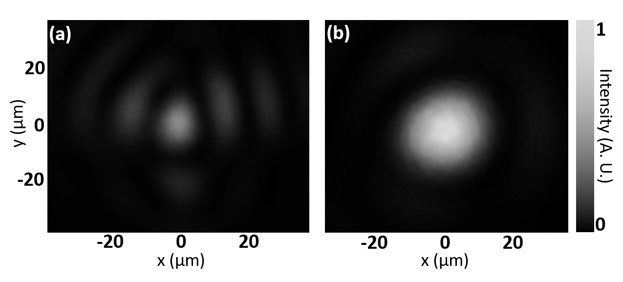
The beam profiles shown in Fig. 2 remained stable throughout the experiment. Through further calibrations, we determined the Drive pulse to have J and fs and the DLA pulse to have J and fs. Because the DLA pulse was selected from the outside of the fully compressed beam and compression was optimized for the pulse center, we see significantly more variability in the duration of the DLA pulse with for more than of the measurements.
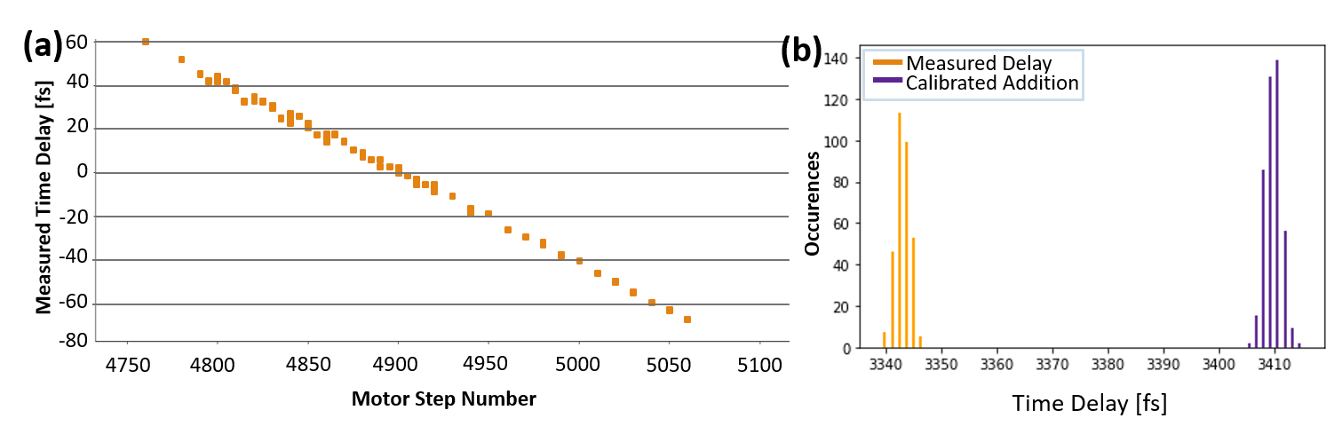
For relative time delay measurements, we used two methods. The first utilized the spectral interferometer shown in Fig. 1(f). Between shot groups the laser was switched from full power to partial power and higher rep rate, then the pointing of beams reflected from the inner and outer components of the segmented mirror was optimized. Then we verified the time delay offset of our spectral interferometer using a flat reference mirror. We would compare this to the measured time delay off our segmented mirror which used the same beam path with the reference mirror pulled to the out position. In the second method we used the spectral interferometry technique from the first method and scanned from m to m we repeated this in both directions. Figure 3(a) shows the results, which demonstrated that the correlation between nominal mirror movement and measured delay was both accurate and reproducible. This told us that we could rely on our closed loop motor to be accurate to within about fs of our intended time delay.
In order to establish our true time delay we measured the intrinsic time delay between the inside and outside of our compressed pulse in shot conditions. This was done by utilizing the dot mask in Fig. 1(a) with a pair of ND filters meant to even the intensity between the inner (Drive) and outer (DLA) parts of the beam while adding a known time delay between them. The beamlets left over after this mask then propagate through the system as they would during a shot until they get to the mask location in Fig. 1(d) where a wedge picks them off to travel to a spectral interferometer at Fig. 1(g). There we measure the true current delay and compare it to the delay added by the ND filters. This comparison is shown in Fig. 3(b) and was measured to be close to fs meaning the DLA pulse inherently arrived fs after the drive pulse before adding or removing any time delay with our segmented mirror.
2.1 Preliminary Results
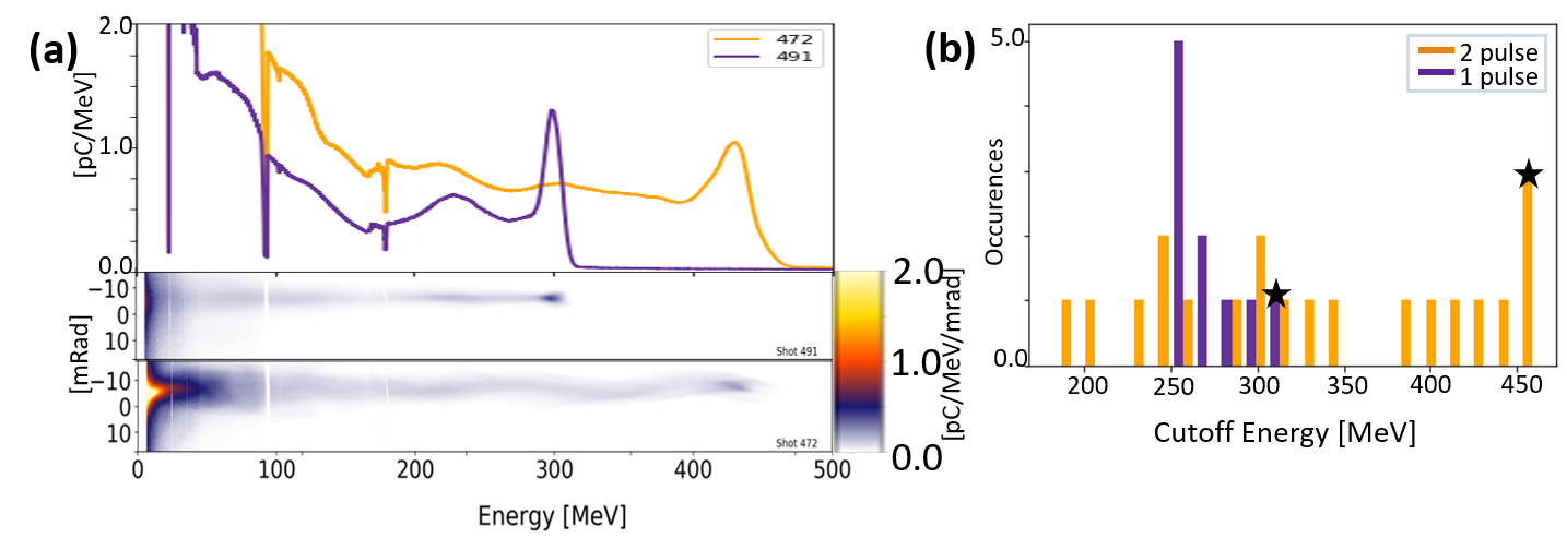
We observed enhancement in the electron energy as a result of this DLA pulse. Fig. 4 shows results obtained in plasma of electron density , for which bubble radius is m, the separation of two co-propagating pulses delayed by fs. This energy enhancement exceeded MeV in our best results [see Fig. 4(a)], but varied from shot to shot as shown in Fig. 4(b). We tentatively attribute these variations to compression instability in the DLA pulse and to the gradual wavelength scale motor motion that occurred as a result of unwanted feedback. This motion would change the way the tail of the drive pulse and the bulk of the DLA pulse interfere, changing the effective intensity profile that the accelerating electrons experience. These variations notwithstanding, the energy enhancements were observed at corresponding to overlap of the DLA pulse with accelerating electrons, and exceeded normal shot-to-shot fluctuations of electron energy observed with only the drive laser pulse.
3 ACKNOWLEDGMENTS
This work was supported by U.S. DoE grant DE-SC0011617. M.D. acknowledges additional support from the Alexander von Humboldt Foundation.
References
- Tajima and Dawson (1979) T. Tajima and J. M. Dawson, Physical Review Letters 43, p. 267 (1979).
- Faure et al. (2006) J. Faure, C. Rechatin, A. Norlin, A. Lifschitz, Y. Glinec, and V. Malka, Nature 444, 737–739 (2006).
- Esarey, Schroeder, and Leemans (2009) E. Esarey, C. Schroeder, and W. Leemans, Reviews of Modern Physics 81, p. 1229 (2009).
- Downer et al. (2018) M. Downer, R. Zgadzaj, A. Debus, U. Schramm, and M. Kaluza, Reviews of Modern Physics 90, p. 035002 (2018).
- Behnke et al. (2013) T. Behnke, J. E. Brau, B. Foster, J. Fuster, M. Harrison, J. M. Paterson, M. Peskin, M. Stanitzki, N. Walker, and H. Yamamoto, arXiv preprint arXiv:1306.6327 (2013).
- Faure et al. (2004) J. Faure, Y. Glinec, A. Pukhov, S. Kiselev, S. Gordienko, E. Lefebvre, J.-P. Rousseau, F. Burgy, and V. Malka, Nature 431, 541–544 (2004).
- Geddes et al. (2004) C. Geddes, C. Toth, J. Van Tilborg, E. Esarey, C. Schroeder, D. Bruhwiler, C. Nieter, J. Cary, and W. Leemans, Nature 431, 538–541 (2004).
- Mangles et al. (2004) S. P. Mangles, C. Murphy, Z. Najmudin, A. G. R. Thomas, J. Collier, A. E. Dangor, E. Divall, P. Foster, J. Gallacher, C. Hooker, et al., Nature 431, 535–538 (2004).
- Zeng et al. (2014) M. Zeng, M. Chen, Z.-M. Sheng, W. B. Mori, and J. Zhang, Physics of Plasmas 21, p. 030701 (2014).
- Couperus et al. (2017) J. Couperus, R. Pausch, A. Köhler, O. Zarini, J. Krämer, M. Garten, A. Huebl, R. Gebhardt, U. Helbig, S. Bock, et al., Nature Communications 8, 1–7 (2017).
- Irman et al. (2018) A. Irman, J. Couperus, A. Debus, A. Köhler, J. Krämer, R. Pausch, O. Zarini, and U. Schramm, Plasma Physics and Controlled Fusion 60, p. 044015 (2018).
- Buck et al. (2013) A. Buck, J. Wenz, J. Xu, K. Khrennikov, K. Schmid, M. Heigoldt, J. M. Mikhailova, M. Geissler, B. Shen, F. Krausz, et al., Physical Review Letters 110, p. 185006 (2013).
- Deng et al. (2019) A. Deng, O. Karger, T. Heinemann, A. Knetsch, P. Scherkl, G. G. Manahan, A. Beaton, D. Ullmann, G. Wittig, A. F. Habib, et al., Nature Physics 15, 1156–1160 (2019).
- Schmid et al. (2010) K. Schmid, A. Buck, C. M. Sears, J. M. Mikhailova, R. Tautz, D. Herrmann, M. Geissler, F. Krausz, and L. Veisz, Physical Review Special Topics-Accelerators and Beams 13, p. 091301 (2010).
- Tsung et al. (2004) F. S. Tsung, R. Narang, W. B. Mori, C. Joshi, R. Fonseca, and L. O. Silva, Physical Review Letters 93, p. 185002 (2004).
- Leemans et al. (2006) W. P. Leemans, B. Nagler, A. J. Gonsalves, C. Tóth, K. Nakamura, C. G. Geddes, E. Esarey, C. Schroeder, and S. Hooker, Nature Physics 2, 696–699 (2006).
- Shaw et al. (2016) J. Shaw, N. Lemos, K. Marsh, F. Tsung, W. Mori, and C. Joshi, Plasma Physics and Controlled Fusion 58, p. 034008 (2016).
- Cipiccia et al. (2011) S. Cipiccia, M. R. Islam, B. Ersfeld, R. P. Shanks, E. Brunetti, G. Vieux, X. Yang, R. C. Issac, S. M. Wiggins, G. H. Welsh, et al., Nature Physics 7, 867–871 (2011).
- Shaw et al. (2018) J. Shaw, N. Lemos, K. Marsh, D. Froula, and C. Joshi, Plasma Physics and Controlled Fusion 60, p. 044012 (2018).
- Zhang, Khudik, and Shvets (2015) X. Zhang, V. N. Khudik, and G. Shvets, Physical Review Letters 114, p. 184801 (2015).
- Zhang et al. (2016) X. Zhang, V. N. Khudik, A. Pukhov, and G. Shvets, Plasma Physics and Controlled Fusion 58, p. 034011 (2016).
- Zhang et al. (2018) X. Zhang, T. Wang, V. Khudik, A. Bernstein, M. Downer, and G. Shvets, Plasma Physics and Controlled Fusion 60, p. 105002 (2018).
- Wang et al. (2019) T. Wang, V. Khudik, A. Arefiev, and G. Shvets, Physics of Plasmas 26, p. 083101 (2019).
- Litos et al. (2014) M. Litos, E. Adli, W. An, C. Clarke, C. Clayton, S. Corde, J. Delahaye, R. England, A. Fisher, J. Frederico, et al., Nature 515, 92–95 (2014).
- Martinez de la Ossa et al. (2019) A. Martinez de la Ossa, R. Assmann, M. Bussmann, S. Corde, J. Couperus Cabadağ, A. Debus, A. Döpp, A. Ferran Pousa, M. Gilljohann, T. Heinemann, B. Hidding, A. Irman, S. Karsch, O. Kononenko, T. Kurz, J. Osterhoff, R. Pausch, S. Schöbel, and U. Schramm, Philosophical Transactions of the Royal Society A 377, p. 20180175 (2019).
- Kneip et al. (2011) S. Kneip, C. McGuffey, F. Dollar, M. Bloom, V. Chvykov, G. Kalintchenko, K. Krushelnick, A. Maksimchuk, S. Mangles, T. Matsuoka, et al., Applied Physics Letters 99, p. 093701 (2011).
- Cole et al. (2015) J. Cole, J. Wood, N. Lopes, K. Poder, R. Abel, S. Alatabi, J. Bryant, A. Jin, S. Kneip, K. Mecseki, et al., Scientific Reports 5, 1–7 (2015).
- Schramm et al. (2017) U. Schramm, M. Bussmann, A. Irman, M. Siebold, K. Zeil, D. Albach, C. Bernert, S. Bock, F. Brack, J. Branco, and J. Couperus, J. Phys. Conf. Ser. 874, p. 012028 (2017).
- Couperus et al. (2016) J. Couperus, A. Köhler, T. Wolterink, A. Jochmann, O. Zarini, H. M. Bastiaens, K. J. Boller, A. Irman, and U. Schramm, Nuclear Instruments and Methods in Physics Research Section A: Accelerators, Spectrometers, Detectors and Associated Equipment 830, 504–509 (2016).
- Köhler et al. (2016) A. Köhler, J. Couperus, O. Zarini, A. Jochmann, A. Irman, and U. Schramm, Nuclear Instruments and Methods in Physics Research Section A: Accelerators, Spectrometers, Detectors and Associated Equipment 829, 265–269 (2016).
- Šmíd et al. (2017) M. Šmíd, I. Gallardo González, H. Ekerfelt, J. Björklund Svensson, M. Hansson, J. C. Wood, A. Persson, S. P. Mangles, O. Lundh, and K. Falk, Review of Scientific Instruments 88, p. 063102 (2017).