Voltage-control of damping constant in magnetic–insulator/topological–insulator bilayers
Abstract
The magnetic damping constant is a critical parameter for magnetization dynamics and the efficiency of memory devices and magnon transport. Therefore, its manipulation by electric fields is crucial in spintronics. Here, we theoretically demonstrate the voltage-control of magnetic damping in ferro- and ferrimagnetic–insulator (FI)/topological–insulator (TI) bilayers. Assuming a capacitor-like setup, we formulate an effective dissipation torque induced by spin-charge pumping at the FI/TI interface as a function of an applied voltage. By using realistic material parameters, we find that the effective damping for a FI with 10 nm thickness can be tuned by one order of magnitude under the voltage with 0.25 V. Also, we provide perspectives on the voltage-induced modulation of the magnon spin transport on proximity-coupled FIs.
Voltage or electric-field control of magnetic properties is fundamentally and technologically crucial for energetically efficient spintronic technologies, Ohno00 ; Song17 such as magnetic random-access memories (MRAMs), Nozaki19 spin transistors, Zutic04 ; Takiguchi19 and spin-wave-based logic gates. Rana19 In these technologies, voltage-control of magnetic anisotropy (VCMA) in thin ferromagnets Weisheit07 ; Duan08 ; Maruyama09 promises energy-efficient reversal of magnetization by a pulsed voltage Shiota12 ; Leon18 ; Chiba20 and manipulation of propagating spin waves with lower power consumption. Rana19a The control of magnetic damping is also highly desirable to increase the performance of spintronic devices. For instance, low magnetic damping allows small critical current densities for magnetization switching and spin-wave excitation by current-induced spin-transfer STTReview and spin-orbit torques. Manchon19 ; Hamadeh14 On the other hand, a high magnetic damping can be beneficial in reducing the data writing time in MRAM devices. For magnonic devices, magnetic damping is a key factor because it governs the lifetime of spin waves or magnons as information carriers. Chumak15 Even if the magnetic damping is a vital material parameter that governs magnetization dynamics in several spintronic devices, its voltage-control is not fully explored except for a few experiments with ferro- and ferrimagnets. Okada14 ; LChen15 ; Rana20 ; Xu19 ; Harder19
The main origin of magnetic dissipation is the spin-orbit interaction (SOI), which creates relaxation paths of the spin-angular momentum into conduction electrons and the lattice. Hence, potential candidates to achieve the voltage-control of magnetic damping are magnetic materials and/or strong SOI systems. Three-dimensional topological insulators (3D TIs), such as , are characterized by band inversion due to a strong SOI Hasan10 ; Qi11 and possess an ideally insulating bulk and spin–momentum locked metallic surface states. Recently, (BSTS) Ando13 and Sn-doped Kushwaha16 have been reported to be ideal 3D TIs with two-dimensional (2D) Dirac electrons on the surface and a highly insulating bulk. For spintronics, the interface between a ferromagnet and a TI can enhance the magnitude of both spin and charge currents. Mellnik14 ; Shiomi14 Some experiments reported Jiang16 ; Wang16 ; Tang18 ; Fanchiang18 the spin-charge conversion at room temperature Kajiwara10 ; Ding20 in a bilayer of TI/ferro- and ferrimagnetic-insulator (FI) such as Y3Fe5O12 (YIG) with very low Gilbert damping constant (). An essential feature of the FI/TI bilayer is that the TI bulk behaves as a semiconductor, enabling the control of the surface carrier density by a voltage. HWang19 Also, magnetically doped TI exhibit VCMA. Fan16 ; Chiba20 Hence, TIs are a promising candidate to achieve the voltage-control of magnetic damping.
In this work, we theoretically demonstrate the voltage-control of magnetic damping in FI/TI bilayers. We formulate an effective dissipation torque induced by spin-charge pumping at the FI/TI interface as a function of a gate voltage . Our main result is that the voltage changes the effective damping by one order of magnitude for a FI with a perpendicular magnetization configuration and 10 nm thickness. Also, we provide perspectives on the modification of magnon scattring time in a FI-based magnonic device.
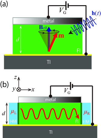
To study the effective damping torque, we consider 2D massless Dirac electrons on the TI surface with the magnetic proximity effect, Jiang16 ; Wang16 ; Tang18 ; Fanchiang18 i.e., coupled to the magnetization of an adjacent FI. The exchange interaction between the surface electrons and the FI magnetization is modeled by a constant spin splitting along the magnetization direction with unit vector (in which is the magnetization vector with the saturation magnetization ). Nomura10 Then, the following 2D Dirac Hamiltonian provides a simple model for the FI/TI interface state Chiba17 :
| (1) |
where is the reduced Planck constant, is the Fermi velocity of the Dirac electrons at zero applied voltage, is the momentum operator, are the unit vectors along the respective Cartesian axes, is the vector of Pauli matrices for the spin, and is the exchange interaction constant. For simplicity, we ignore here the particle–hole asymmetry and the hexagonal warping effect in the surface bands. Also, and are assumed to be temperature independent. VFTIndep2 Note that we operate in the weak magnetic coupling limit, and therefore self-consistent treatment for the induced gap () Efimkin14 is not necessary.
Let us begin by calculating the dissipation torque induced by the spin-charge pumping Yokoyama10 ; Sakai14 ; Shiomi14 ; Ndiaye17 of a dynamic magnetization in FI/TI bilayers. A precessing magnetization, driven by ferromagnetic resonance (FMR), as shown in Fig. 1, can be regarded as an effective vector potential with the electron charge , which drives a charge current via an effective electric field (see the supplementary material), i.e.,
| (2) |
where and are longitudinal and transverse (anomalous-Hall) conductivities, respectively, and depend on the component of the magnetization () Chiba17 . From the Hamiltonian (1), the velocity operator depends linearly on . Therefore, the nonequilibrium spin polarization (in units of m-2) is a linear function of the charge current on the TI surface, i.e., . This nonequilibrium spin polarization exerts a dissipation torque on the magnetization, , namely
| (3) |
with
| (4) |
where is the gyromagnetic ratio and is the thickness of the FI layer. Equation (3) is equivalent to the charge-pumping-induced damping-like torque that Ndiaye et al. derived using the Onsager reciprocity relation for a current-induced spin-orbit torque. Ndiaye17 The first term in Eq. (3) originates from the magnetoelectric coupling (the Chern–Simons term) Nomura10 ; Garate10 and renormalizes the gyromagnetic ratio. By using parameters listed in TABLE 1, meV, and nm, is estimated even by using at 0 K as the upper value. Chiba17 Thus, we disregard the renormalization of the gyromagnetic ratio. In contrast, the second term in Eq. (3) stems from the Rashba–Edelstein effect due to the spin-momentum locking on the TI surface Yokoyama10 and contributes to magnetic damping. Since we are interested in voltage-control of magnetic damping, we hereafter focus on in this study.
According to Eq. (4), the electric field effect on the conductivity can be used to control the magnetic dissipation. Namely, the voltage–induced change of the interfacial density of states in renders the TI a more or less efficient spin sink. The damping enhancement depends on the chemical potential , measured from the original band-touching (Dirac) point. At room temperature, or below it, the thermal energy is much smaller than the Fermi one, , with the temperature and the Boltzmann constant. Then, we can use the following Sommerfeld expansion of the chemical potential
| (5) |
with the voltage-dependent Fermi energy, Chiba20 , given by
| (6) |
where is the permittivity of a FI and is the intrinsic carrier density, i.e., at . Note that we can define a voltage-dependent surface electron density that shows the underlying mechanism behind the voltage-control of interfacial phenomena in insulating bilayers with surface carriers, which goes beyond topological materials. Namely, a voltage increases or decreases the effective electron density and therefore enhances or weakens all effects that depend on this density, including isotropic RKKYVolt and anisotropicDMIVolt exchange interactions, emergence of magnetization in metals, PlatVolt perpendicular magnetic anisotropy, Nozaki19 ; Maruyama09 and spin-orbit torques. Chiba20 The voltage-generated change in the surface density is equivalent to an interfacial Fermi energy shift. In this work, we predict that the spin-charge pumping efficiency is also modulated, an effect that may also appear in usual FInormal metal bilayers since the spin-mixing conductance depends on the electronic density. SpinPumpingCahaya
We investigate the effect of electric-gate on the effective damping so that we assume hereafter that the low-energy Dirac Hamiltonian (1) is an accurate description for a momentum cut , in which is the bulk bandgap of TIs Tserkovnyak15 (see Fig. 2 (c)). Sufficiently far from the Dirac point (, is the transport relaxation time), the electron scattering can be treated by the first Born approximation. Adam09 With this, the longitudinal conductivity reads Chiba19
| (7) |
where is the Fermi-Dirac distribution, the energy is the eigenvalue of Eq. (1), and is the transport relaxation time of massless Dirac electrons within the Born approximation for impurity and phonon scatterings. By applying the Matthiessen rule,
| (8) |
where (in units of ) parameterize contribution of the impurity scattering, Ivanov18 ; Giraud12 is the impurity concentration, and is the scattering potential. Also, contribution to the transport relaxation time from the phonon scattering Ivanov18 ; Giraud12 can be approximated by (in units of ), where is the mass density of the quintuple layer (QL) in the TI crystal structure, is the thickness of one atomic layer in 1 QL of TIs, is the longitudinal phonon velocity, and is the deformation potential constant.
| Symbol | Value | Unit | |
|---|---|---|---|
| 11footnotemark: 1BSTS Fermi velocity | |||
| 11footnotemark: 1BSTS bulk band gap | 300 | meV | |
| 22footnotemark: 2YIG gyromagnetic ratio | 1.76 | ||
| 22footnotemark: 2YIG Gilbert damping constant | 6.7 | ||
| 22footnotemark: 2YIG saturation magnetization | 1.56 | ||
| 33footnotemark: 3YIG relative permittivity | 15 |
Reference Ando13, , 22footnotemark: 2Reference Kajiwara10, , 33footnotemark: 3Reference Sadhana09, .
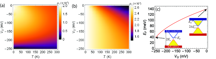
Figures 2 (a) and (b) show the and dependence of the effective damping enhancement for out-of-plane () and in-plane () magnetization configurations, respectively. Also, Fig. 2 (c) illustrates the voltage modulation of in TI. The bulk damping constant can be influenced by material and device parameters, such as SOI and magnetic anisotropies Ding20 . However, we predict the voltage-modulation of the damping enhancement by spin-charge pumping. Therefore, our results are independent of the intrinsic dissipation mechanisms. At the FI/TI interface, orbital hybridization between TI and the 3 transition metal in FI, such as YIG, deforms the TI surface states, which might shift the Dirac point to the lower energy and lift up , Marmolejo17 so that we consider relatively high value meV with the corresponding carrier density of the order of cm-2. Also, is used within the values reported experimentally in FI-attached TIs. Hirahara17 ; Mogi19 For impurity parameters, we use cm-2 and keVÅ2 based on an analysis of the transport properties of a TI surface. Chiba19 We could not find estimates of the phonon scattering for BSTS in the literature so that we adopt those of non-substituted Bi2Te3 being , eV, nm, and in Ref. Huang08, . These scattering parameters describe a relatively clean interface with the sheet resistance k, which is one order less than that of experiments. In Figs. 2 (a) and (b), monotonically decreases with increasing at a fixed while it has peaks for changing at a fixed (see also the inset of Fig. 3). This feature reflects thermal excitation of surface carriers into the bulk states (), reducing the spin-charge-pumping contribution. With the out-of-plane configuration, can be tuned by one order of magnitude under the voltage, while changes by less than a factor two with the in-plane state, which suggests that the out-of-plane configuration is superior in controllability. The calculated dependence of damping enhancement at for the in-plane configuration agrees with a few experiments with the FI/TI bilayer. Tang18 ; Liu20 Note that at much lower than meV, our calculation with the in-plane configuration breaks down because of the finite level broadening due to the higher-order impurity scattering. Shon98 The –dependent FMR is characterized by the Landau-Lifshitz-Gilbert theory in the supplementary material.
The electric manipulation of magnon spin transport is a relevant topic in spintronics. For example, in YIG with an injector and a detector Pt contact, changes of the magnon spin conductivity can be obtained by using a third electrode that changes the magnon density, Cornelissens2018 ; EControlOfMagnTransp ; ByAHEFF potentially providing a functionality similar to the one a field-effect transistors. Damping compensation by current-driven torques DampComp1 ; DampComp2 in magnetic heterostructures also influences magnon transport. Here, we provide a perspective on the electric-field-induced modulation of magnon scattering time, . Magnons can be injected and detected by their interconversion with charge currents in adjacent heavy metals (HMs) through the direct and inverse spin-Hall effects. Kajiwara10 Similar to charge transport induced by an electrochemical potential gradient, a magnon spin current can be driven by the gradient of a magnon chemical potential injected by an external source. Cornelissen16 ; Basso16 Magnon transport through a FI can be controlled by the gate voltage that modulates the effective damping in Eq. (4).
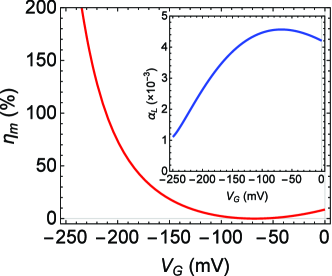
So far, the magnon spin transport in the FI/TI bilayer lacks microscopic theory with few exceptions.Okuma17 ; Imai18 However, from the bulk of magnon spin transport, Cornelissen16 the control of results in the modification of all transport properties, including the magnon spin conductivity. In the presence of a TI contact, interfacial magnons are scattered by conducting Dirac electrons on the TI surface. Yasuda16 Considering a very thin ferromagnet that can be modeled by a 2D magnet. The inset of Fig. 3 shows that the damping enhancement is at least one order of magnitud larger than the bulk one of YIG. Kajiwara10 ; Ding20 Accordingly, let us assume that interfacial magnons are absorbed by transferring their energy and angular momentum to Dirac electrons at a rate . Cornelissen16 While there is no know microscopic expression for the magnon spin conductivity in the present system, bulk magnon transport obeys the relationship , Cornelissens2018 ; EControlOfMagnTransp where is the magnon spin conductivity. In our case, the scattering time is dominated by the magnon-relaxation process into the FI/TI interface. To estimate an effect of electric-gate on the magnon spin transport, we define the modulation efficiency
| (9) |
where mV for Fig. 3) gives the maximum value of (and therefore the minimum value of ). In principle, depends on through not only but also via magnon dispersion relation, , Cornelissen16 including a –dependent magnetic anisotropy. However, this –dependence is quite small even for a FI with 2 nm thickness (see the supplementary material), so that we disregard the influence of the magnon gap in the following calculation. Figure 3 shows -dependence of the modulation efficiency at room temperature in which the strongly nonlinear behavior is interpreted as follows. Down to , is affected by the thermal excitation of surface carriers, which makes a peak around . From to , the thermal excitation is suppressed, so that monotonically decreases with due to the reduction of the Fermi surface. Hence, in this regime, one can effectively modulate the magnon spin transport by the voltage.
In summary, we have theoretically demonstrated the voltage-control of magnetic damping in ferro- ferrimagnetic insulator (FI)/topological insulator (TI) bilayers. Assuming a capacitor-like setup, we formulate an effective damping torque induced by spin-charge pumping at the FI/TI interface as a gate voltage function. The presence of a perpendicular electric field results in a shift of the Fermi level or, equivalently, a modified interfacial electron density, increasing or decreasing the efficiency of the pumping process. We studied the consequences of this damping enhancement using realistic material parameters for FI and TI. We found that the effective damping with the out-of-plane magnetization configuration can be modulated by one order of magnitude under the voltage with 0.25 V. The present results motivate an application: the magnon scattering time can be tuned by a gate voltage, potentially allowing for a magnon transistor type of application. A complete quantitative description of the latter requires a microscopic theory of magnon spin transport in FI/TI bilayers, which might remain an unexplored issue. The voltage-control of magnetic damping paves the way for low-power spintronic and magnonic technologies beyond the current-based control.
See the supplementary material for the calculation of the spin-charge pumping in FI/TI bilayers, the characterization of the FMR under several values of the applied voltage, the influence of –dependence of the anisotropy in the magnon dispersion.
We thank Camilo Ulloa and Nicolas Vidal-Silva for fruitful discussions. This work was supported by Grants-in-Aid for Scientific Research (Grant No. 20K15163 and No. 20H02196) from the JSPS and Postdoctorado FONDECYT 2019 Folio 3190030.
Data Availability
The data that support the findings of this study are available from the corresponding author upon reasonable request.
References
- (1) H. Ohno, D. Chiba, F. Matsukura, T. Omiya, E. Abe, T. Dietl, Y. Ohno, and K. Ohtani, ”Electric-field control of ferromagnetism,” Nature 408, 944 (2000).
- (2) C. Song, B. Cui, F. Li, X. Zhou, and F. Pan, ”Recent progress in voltage control of magnetism: Materials, mechanisms, and performance,” Prog. Mater. Sci. 87, 33 (2017).
- (3) T. Nozaki, T. Yamamoto, S. Miwa, M. Tsujikawa, M. Shirai, S. Yuasa, and Y. Suzuki, ”Recent Progress in the Voltage-Controlled Magnetic Anisotropy Effect and the Challenges Faced in Developing Voltage-Torque MRAM,” Micromachines 10, 327 (2019).
- (4) I. Žutić, J. Fabian , and S. Das Sarma, ”Spintronics: Fundamentals and applications,” Rev. Mod. Phys. 76, 323 (2004).
- (5) K. Takiguchi, L. D. Anh, T. Chiba, T. Koyama, D. Chiba, and M. Tanaka, ”Giant gate-controlled proximity magnetoresistance in semiconductor-based ferromagnetic-non-magnetic bilayers,” Nat. Phys. 15, 1134 (2019).
- (6) B. Rana and Y. Otani, ”Towards magnonic devices based on voltage-controlled magnetic anisotropy,” Commun. Phys. 2, 90 (2019).
- (7) M. Weisheit, S. F’́ahler, A. Marty, Y. Souche et al., ”Electric field-induced modification of magnetism in thin-film ferromagnets,” Science 315, 349 (2007).
- (8) C.-G. Duan, J. P. Velev, R. F. Sabirianov, Z. Zhu, J. Chu, S. S. Jaswal, and E. Y. Tsymbal, ”Surface magnetoelectric effect in ferromagnetic metal films,” Phys. Rev. Lett. 101, 137201 (2008).
- (9) T. Maruyama, Y. Shiota, T. Nozaki, K. Ohta et al., ”Large voltage-induced magnetic anisotropy change in a few atomic layers of iron,” Nat. Nanotech. 4, 158 (2009).
- (10) Y. Shiota, T. Nozaki, F. Bonell, S. Murakami, T. Shinjo, and Y. Suzuki, ”Induction of coherent magnetization switching in a few atomic layers of FeCo using voltage pulses,” Nat. Mater. 11, 39 (2012).
- (11) A. O. Leon, A. B. Cahaya, and G. E. W. Bauer, ”Voltage Control of Rare-Earth Magnetic Moments at the Magnetic-Insulator-Metal Interface,” Phys. Rev. Lett. 120, 027201 (2018).
- (12) T. Chiba and T. Komine, ”Voltage–Driven Magnetization Switching via Dirac Magnetic Anisotropy and Spin–Orbit Torque in Topological–Insulator–Based Magnetic Heterostructures,” Phys. Rev. Appl. 14, 034031 (2020).
- (13) B. Rana and Y. Otani, ”Voltage-Controlled Reconfigurable Spin-Wave Nanochannels and Logic Devices,” Phys. Rev. Appl. 9, 224412 (2019).
- (14) D. C. Ralph and M. D. Stiles, ”Spin transfer torques,” J. Magn. Mag. Mater. 320, 1190 (2008).
- (15) A. Manchon, J. elezný, I. M. Miron, T. Jungwirth, J. Sinova, A. Thiaville, K. Garello, and P. Gambardella, ”Current-induced spin-orbit torques in ferromagnetic and antiferromagnetic systems,” Rev. Mod. Phys. 91, 035004 (2019).
- (16) A. Hamadeh, O. d’Allivy Kelly, C. Hahn, H. Meley, R. Bernard, A. H. Molpeceres, V. V. Naletov, M. Viret, A. Anane, V. Cros, S. O. Demokritov, J. L. Prieto, M. Muñoz, G. de Loubens, and O. Klein, ”Full Control of the Spin-Wave Damping in a Magnetic Insulator Using Spin-Orbit Torque,” Phys. Rev. Lett. 113, 197203 (2014).
- (17) A. V. Chumak, V. I. Vasyuchka, A. A. Serga, and B. Hillebrands, ”Magnon spintronics,” Nat. Phys. 11, 453 (2015).
- (18) A. Okada, S. Kanai, M. Yamanouchi, S. Ikeda, F. Matsukura, and H. Ohno, ”Electric-field effects on magnetic anisotropy and damping constant in Ta/CoFeB/MgO investigated by ferromagnetic resonance,” Appl. Phys. Lett. 105, 052415 (2014).
- (19) L. Chen, F. Matsukura, and H. Ohno, ”Electric-field Modulation of Damping Constant in a Ferromagnetic Semicon- ductor (Ga,Mn)As,” Phys. Rev. Lett. 115, 057204 (2015).
- (20) B. Rana, C. Ashu Akosa, K. Miura, H. Takahashi, G. Tatara, and Y. Otani, ”Nonlinear Control of Damping Constant by Electric Field in Ultrathin Ferromagnetic Films,” Phys. Rev. Appl. 14, 014037 (2020).
- (21) S.-J. Xu, X. Fan, S.-M. Zhou, X. Qiu, and Z. Shi, “Gate voltage tuning of spin current in Pt/yttrium iron garnet heterostructure,” J. Phys. D: Appl. Phys. 52 175304 (2019).
- (22) L. Wang, Z. Lu, J. Xue, P. Shi, Y. Tian, Y. Chen, S. Yan, L. Bai, and M. Harder, “Electrical Control of Spin-Mixing Conductance in a /Platinum Bilayer,” Phys. Rev. Appl. 11, 044060 (2019).
- (23) M. Z. Hasan and C. L. Kane, ”Rev. Colloquium: Topological insulators,” Mod. Phys. 82, 3045 (2010).
- (24) X.-L. Qi and S.-C. Zhang, ”Topological insulators and superconductors,” Rev. Mod. Phys. 83, 1057 (2011).
- (25) Y. Ando, ”Topological insulator materials,” J. Phys. Soc. Jpn. 82, 102001 (2013).
- (26) S. K. Kushwaha, I. Pletikosić, T. Liang, A. Gyenis et al., ”Sn-doped bulk crystal topological insulator with excellent properties,” Nat. Commun. 7, 11456 (2016).
- (27) A. R. Mellnik, J. S. Lee, A. Richardella, J. L. Grab, P. J. Mintun, M. H. Fischer, A. Vaezi, A. Manchon, E.-A. Kim, N. Samarth, and D. C. Ralph, ”Spin-transfer torque generated by a topological insulator,” Nature 511, 449 (2014).
- (28) Y. Shiomi, K. Nomura, Y. Kajiwara, K. Eto, M. Novak, K. Segawa, Y. Ando, and E. Saitoh, ”Spin-Electricity Conversion Induced by Spin Injection into Topological Insulators,” Phys. Rev. Lett. 113, 196601 (2014).
- (29) Z. Jiang, C.-Z. Chang, M. R. Masir, C. Tang, Y. Xu, J. S. Moodera, A. H. MacDonald, and J. Shi, ”Enhanced spin Seebeck effect signal due to spin-momentum locked topological surface states,” Nat. Commun. 7, 11458 (2016).
- (30) H. Wang, J. Kally, J. S. Lee, T. Liu, H. Chang, D. Reifsnyder H., K. A. Mkhoyan, M. Wu, A. Richardella, and N. Samarth, ”Surface-State-Dominated Spin-Charge Current Conversion in Topological-Insulator-Ferromagnetic-Insulator Heterostructures,” Phys. Rev. Lett. 117, 076601 (2016).
- (31) C. Tang, Q. Song, C.-Z. Chang, Y. Xu, Y. Ohnuma, M. Matsuo, Y. Liu, W. Yuan, Y. Yao, J. S. Moodera, S. Maekawa, W. Han, and J. Shi, ”Dirac surface state-modulated spin dynamics in a ferrimagnetic insulator at room temperature,” Sci. Adv. 4, eaas8660 (2018).
- (32) Y. T. Fanchiang, K. H. M. Chen, C. C. Tseng, C. C. Chen, C. K. Cheng, S. R. Yang, C. N. Wu, S. F. Lee, M. Hong, and J. Kwo, ”Strongly exchange-coupled and surface-state-modulated magnetization dynamics in Bi2Se3/yttrium iron garnet heterostructures,” Nat. Commun. 9, 223 (2018).
- (33) Y. Kajiwara, K. Harii, S. Takahashi, J. Ohe, K. Uchida, M. Mizuguchi, H. Umezawa, H. Kawai, K. Ando, K. Takanashi, S. Maekawa, and E. Saitoh,” Transmission of electrical signals by spin-wave interconversion in a magnetic insulator”, Nature 464, 262 (2010).
- (34) J. Ding, C. Liu, Y. Zhang, U. Erugu, Z. Quan, R. Yu, E. McCollum, S. Mo, S. Yang, H. Ding, X. Xu, J. Tang, X. Yang, and M. Wu, ”Nanometer-Thick Yttrium Iron Garnet Films with Perpendicular Anisotropy and Low Damping,” Phys. Rev. Appl. 14, 014017 (2020).
- (35) H. Wang, J. Kally, C. Sahin, T. Liu, W. Yanez, E. J. Kamp, A. Richardella, M. Wu, M. E. Flatté, and N. Samarth, ”Fermi level dependent spin pumping from a magnetic insulator into a topological insulator”, Phys. Rev. Res. 81, 012014(R) (2019).
- (36) Y. Fan, X. Kou, P. Upadhyaya, Q. Shao, L. Pan, M. Lang, X. Che, J. Tang, M. Montazeri, K. Murata, L.-T. Chang, M. Akyol, G. Yu, T. Nie, K. L. Wong, J. Liu, Y. Wang, Y. Tserkovnyak, and K. L. Wang, ”Electric-field control of spin-orbit torque in a magnetically doped topological insulator,” Nat. Nanotechnol. 11, 352 (2016).
- (37) K. Nomura and N. Nagaosa, ”Electric charging of magnetic textures on the surface of a topological insulator,” Phys. Rev. B 82, 161401(R) (2010).
- (38) T. Chiba, S. Takahashi, and G. E. W. Bauer, ”Magnetic-proximity-induced magnetoresistance on topological insulators,” Phys. Rev. B 95, 094428 (2017).
- (39) D. K. Efimkin and V. Galitski, ”Self-consistent theory of ferromagnetism on the surface of a topological insulator,” Phys. Rev. B 89, 115431 (2014).
- (40) Z.-H. Pan, E. Vescovo, A. V. Fedorov, G. D. Gu, and T. Valla, ”Persistent coherence and spin polarization of topological surface states on topological insulators,” Phys. Rev. B 88, 041101(R) (2013).
- (41) T. Yokoyama, J. Zang, and N. Nagaosa, ”Theoretical study of the dynamics of magnetization on the topological surface,” Phys. Rev. B 81, 241410(R) (2010).
- (42) A. Sakai and H. Kohno, ”Spin torques and charge transport on the surface of topological insulator,” Phys. Rev. B 89, 165307 (2014).
- (43) P. B- Ndiaye, C. A. Akosa, M. H. Fischer, A. Vaezi, E-A. Kim, and A. Manchon, ”Dirac spin-orbit torques and charge pumping at the surface of topological insulators,” Phys. Rev. B 96, 014408 (2017).
- (44) I. Garate and M. Franz, ”Inverse Spin-Galvanic Effect in the Interface between a Topological Insulator and a Ferromagnet,” Phys. Rev. Lett. 104, 146802 (2010).
- (45) A. O. Leon, J. d’A Castro, J. C. Retamal, A. B. Cahaya, and D. Altbir, ”Manipulation of the RKKY exchange by voltages,” Phys. Rev. B. 100, 014403 (2019).
- (46) K. Nawaoka, S. Miwa, Y. Shiota, N. Mizuochi, and Y. Suzuki, ”Voltage induction of interfacial Dzyaloshinskii–Moriya interaction in Au/Fe/MgO artificial multilayer,” Appl. Phys. Express 8, 063004 (2015).
- (47) S. Miwa, M. Suzuki, M. Tsujikawa, K. Matsuda et al., ”Voltage controlled interfacial magnetism through platinum orbits,” Nat. Comm. 8, 15848 (2017).
- (48) A. B. Cahaya, A. O. Leon, and G. E. W. Bauer, ”Crystal field effects on spin pumping,” Phys. Rev. B 96, 144434 (2017).
- (49) K. Sadhana, R. S. Shinde, and S. R. Murthy, ”Synthesis of nanocrystalline yig using microwave-hydrothermal method,” International Journal of Modern Physics B 23, 3637-3642 (2009), publisher: World Scientific Publishing Co.
- (50) Y. Tserkovnyak, D. A. Pesin, and D. Loss, ”Spin and orbital magnetic response on the surface of a topological insulator,” Phys. Rev. B 91, 041121(R) (2015).
- (51) S. Adam, P. W. Brouwer, and S. Das Sarma, ”Crossover from quantum to Boltzmann transport in graphene,” Phys. Rev. B 79, 201404(R) (2009).
- (52) T. Chiba and S. Takahashi, ”Transport properties on an ionically disordered surface of topological insulators: Toward high-performance thermoelectrics,” J. Appl. Phys. 126, 245704 (2019).
- (53) Y. V. Ivanov, A. T. Burkov, and D. A. P.-Severin, ”Thermoelectric properties of topological insulators,” Phys. Status Solidi B 255 1800020 (2018).
- (54) S. Giraud, A. Kundu, and R. Egger, ”Electron-phonon scattering in topological insulator thin films,” Phys. Rev. B 85, 035441 (2012).
- (55) J. M. Marmolejo-Tejada, K. Dolui, P. Lazić, P.-H. Chang, S. Smidstrup, D. Stradi, K. Stokbro, and B. K. Nikolić, ”Proximity Band Structure and Spin Textures on Both Sides of Topological-Insulator/Ferromagnetic-Metal Interface and Their Charge Transport Probes,” Nano Lett. 17, 5626 (2017).
- (56) T. Hirahara, S. V. Eremeev, T. Shirasawa, Y. Okuyama, T. Kubo, R. Nakanishi, R. Akiyama, A. Takayama, T. Hajiri, S. Ideta et al., “Large-gap magnetic topological heterostructure formed by subsurface incorporation of a ferromagnetic layer,” Nano. Lett. 17, 3493 (2017).
- (57) M. Mogi, T. Nakajima, V. Ukleev, A. Tsukazaki, R. Yoshimi, M. Kawamura, K. S. Takahashi, T. Hanashima, K. Kakurai, T. Arima, M. Kawasaki, and Y. Tokura, ”Large Anomalous Hall Effect in Topological Insulators with Proximitized Ferromagnetic Insulators,” Phys. Rev. Lett. 123, 016804 (2019).
- (58) B.-L. Huang and M. Kaviany, ”Ab initio and molecular dynamics predictions for electron and phonon transport in bismuth telluride,” Phys. Rev. B 77, 125209 (2008).
- (59) T. Liu, J. Kally, T. Pillsbury, C. Liu, H. Chang, J. Ding, Y. Cheng, M. Hilse, R. E.-Herbert, A. Richardella, N. Samarth, and M. Wu, ”Changes of Magnetism in a Magnetic Insulator due to Proximity to a Topological Insulator,” Phys. Rev. Lett. 125, 017204 (2020).
- (60) N. H. Shon and T. Ando, ”Quantum Transport in Two-Dimensional Graphite System,” J. Phys. Soc. Jpn. 67, 2421 (1998).
- (61) L. J. Cornelissen, J. Liu, B. J. van Wees, and R. A. Duine, ”Spin-Current-Controlled Modulation of the Magnon Spin Conductance in a Three-Terminal Magnon Transistor,” Phys. Rev. Lett. 120, 097702 (2018).
- (62) J. Liu, X-Y. Wei, B. J. van Wees, G. E. W. Bauer, and J. Ben Youssef, ”Electrically induced strong modulation of magnons transport in ultrathin magnetic insulator films,” arXiv:2011.07800v1.
- (63) O. Alves Santos, F. Feringa, K.S. Das, J. Ben Youssef, and B.J. van Wees, ”Efficient Modulation of Magnon Conductivity in Y3Fe5O12 Using Anomalous Spin Hall Effect of a Permalloy Gate Electrode,” Phys. Rev. Applied 15, 014038 (2021).
- (64) V. E. Demidov, S. Urazhdin, A. B. Rinkevich, G. Reiss, and S. O. Demokritov, ”Spin Hall controlled magnonic microwaveguides,” Appl. Phys. Lett. 104, 152402 (2014).
- (65) T. Wimmer, M. Althammer, L. Liensberger, N. Vlietstra, S. Geprägs, M. Weiler, R. Gross, and H. Huebl, ”Spin Transport in a Magnetic Insulator with Zero Effective Damping,” Phys. Rev. Lett. 123, 257201 (2019).
- (66) L. J. Cornelissen, K. J. H. Peters, G. E. W. Bauer, R. A. Duine, and B. J. van Wees, ”Magnon spin transport driven by the magnon chemical potential in a magnetic insulator”, Phys. Rev. B 94, 014412 (2016).
- (67) V. Basso, E. Ferraro, and M. Piazzi, ”Thermodynamic transport theory of spin waves in ferromagnetic insulators,” Phys. Rev. B 94, 144422 (2016).
- (68) N. Okuma and K. Nomura, ”Microscopic derivation of magnon spin current in a topological insulator/ferromagnet heterostructure,” Phys. Rev. B 95, 115403 (2017).
- (69) Y. Imai, and H. Kohno, ”Theory of Cross-correlated Electron–Magnon Transport Phenomena: Case of Magnetic Topological Insulator,” J. Phys. Soc. Jpn. 87, 073709 (2018).
- (70) K. Yasuda, A. Tsukazaki, R. Yoshimi, K. S. Takahashi, M. Kawasaki, and Y. Tokura, ”Large Unidirectional Magnetoresistance in a Magnetic Topological Insulator,” Phys. Rev. Lett. 117, 127202 (2016).