Enhancing Heat Transport in Multiphase Rayleigh-Bénard Turbulence by Changing the Plate-Liquid Contact Angles
Abstract
This numerical study presents a simple but extremely effective way to considerably enhance heat transport in turbulent wall-bounded multiphase flows, namely by using oleophilic walls. As a model system, we pick the Rayleigh-Bénard setup, filled with an oil-water mixture. For oleophilic walls, using only volume fraction of oil in water, we observe a remarkable heat transport enhancement of more than as compared to the pure water case. In contrast, for oleophobic walls, the enhancement is only of about as compared to pure water. The physical explanation of the heat transport increment for oleophilic walls is that thermal plumes detach from the oil-rich boundary layer and carry the heat with them: In the bulk, the oil-water interface prevents the plumes from mixing with the turbulent water bulk and to diffuse their heat. To confirm this physical picture, we show that the minimum amount of oil necessary to achieve the maximum heat transport is set by the volume fraction of the thermal plumes. Our findings provide guidelines of how to optimize heat transport in wall-bounded thermal turbulence. Moreover, the physical insight of how coherent structures are coupled with one of the phases of a two-phase system has very general applicability for controlling transport properties in other turbulent wall-bounded multiphase flows.
keywords:
1 Introduction
The key property of a turbulent flow is its ability to efficiently transport heat, mass, and/or momentum. Understanding this property allows to control the global transport, enhance or reduce it, which is not only of fundamental interest, but also highly relevant in various industrial applications. For example one can think of heat transfer enhancement for cooling applications (Dhir, 1998) or drag reduction in pipe or channel flow (Bushnell, 2015; Chung et al., 2021). A typical way to control integral properties is by manipulating coherent turbulent structures, which play a crucial role in the global transport (Smits et al., 2011; Holmes et al., 2012; Haller, 2015; Graham & Floryan, 2021). An example is in thermally driven turbulence where the global heat transport can be enhanced by manipulating the coherent thermal plumes – a major heat carrier in thermal convection (Ahlers et al., 2009; Lohse & Xia, 2010; Chilla & Schumacher, 2012; Shishkina, 2021).
Indeed, previous studies have proposed many different methods to enhance heat transport related to thermal plume manipulation: One method is to promote the detachment of plumes from the boundary layers by adding surface roughness (Shen et al., 1996; Ciliberto & Laroche, 1999; Du & Tong, 2000; Ahlers et al., 2009; Salort et al., 2014; Wagner & Shishkina, 2015; Xie & Xia, 2017; Zhu et al., 2017; Jiang et al., 2018) or adding shear (Bergman et al., 2011; Pirozzoli et al., 2017; Blass et al., 2020; Wang et al., 2020a). Another method is to confine the system in span-wise direction in order to increase the coherence of the thermal plumes and thus the heat transport (Huang et al., 2013; Chong et al., 2015, 2017).
However, also the addition of a new phase can enhance heat transport. For example, the mechanical injection of air bubbles (Gvozdić et al., 2018; Ng et al., 2020) or nucleating vapor bubbles by boiling (Dhir, 1998; Zhong et al., 2009; Biferale et al., 2012; Lakkaraju et al., 2013; Guzman et al., 2016) are both quite efficient heat transfer enhancement strategies. While in the former case this is purely due to the extra mechanical stirring by the rising buoyant bubbles, in the latter case the vapor bubbles also act as direct heat carriers. But as shown by Wang et al. (Wang et al., 2019, 2020b), a considerable heat transfer can also emerge when the second phase has comparable density, even for small volume fraction of the second phase.
In this study, we present another, novel, and simple way to substantially enhance heat transfer in wall-bounded thermally driven two-phase turbulence, namely by manipulating the wettability of the walls. We then reveal the underlying physics of the enhancement and in particular the crucial role of the interaction between the coherent structures (plumes) and the second phase. As paradigmatic example to study turbulent heat transfer in wall-bounded systems, we pick Rayleigh-Bénard (RB) convection (Ahlers et al., 2009; Lohse & Xia, 2010; Chilla & Schumacher, 2012; Shishkina, 2021). The system consists of a two-phase fluid in a box heated from below and cooled from above. Next to water, we use oil as a second phase, with its higher heat-conduction properties as compared to water. In our setup the top and the bottom walls are either both oleophilic or both oleophobic. With oleophilic walls, we reveal a novel flow dynamics, namely an “expressway” of oil for the thermal plumes. When thermal plumes detach from the oil-rich thermal boundary layers, they can be transported together with the oil phase. These oil-rich thermal plumes act as the dominant heat transport phase, bypassing the water phase. Thus the global heat transfer is significantly enhanced. We further reveal a strong correlation between the oil phase and the thermal plumes in the oleophilic cases, and show that the minimum amount of oil to achieve maximum heat transport is set by the volume fraction of thermal plumes.
The organization of this paper is as follows. The numerical methodology is introduced in Section 2. The main results on turbulent RB convection with multiphase is presented in Section 3. The mechanism of heat transfer enhancement is revealed in Section 4. The paper ends with conclusions and an outlook.
2 Methodology
The numerical method used here combines the phase-field model (Jacqmin, 1999; Ding et al., 2007; Liu & Ding, 2015; Soligo et al., 2021) and a direct numerical simulations solver for the Navier-Stokes equations namely AFiD, which is a second-order finite-difference open-source solver (Verzicco & Orlandi, 1996; van der Poel et al., 2015). This method is developed to simulate the turbulence with two immiscible fluids and well validated in Liu et al. (2021a, b) by comparing the results to previous experimental, theoretical, and numerical results. The mass conservation is ensured by using the method of Wang et al. (2015). Various test cases in multiphase turbulence are extensively discussed in Liu et al. (2021b).
2.1 Governing equations
In the phase-field model, the evolution of the volume fraction of water, , is governed by the Cahn-Hilliard equation,
| (1) |
where is the flow velocity, and the chemical potential. We set the Péclet number and the Cahn number according to the criteria proposed in (Ding et al., 2007; Liu & Ding, 2015), where is the mesh size and the domain height.
The flow is governed by the Navier-Stokes equations, the heat transfer equation and the incompressibility condition,
| (2) |
| (3) |
| (4) |
where is the dimensionless temperature. We define all dimensionless fluid properties (indicated by ), including the density , the dynamic viscosity , the kinematic viscosity , the thermal conductivity , the thermal expansion coefficient , the thermal diffusivity , and the specific heat capacity , in a uniform way as follows,
| (5) |
where is the ratio of the material properties of oil and water. Here the surface tension force is defined as , and the gravity with being the unit vector in vertical direction. Besides the property ratios, the global dimensionless numbers controlling the flow are , , and , where is the temperature difference between the bottom and top plates and the free-fall velocity, and the surface tension coefficient. The response parameter is the Nusselt number with being the dimensional heat transfer. Note that the governing equations are normalized by the properties of water. Therefore, only global dimensionless numbers (e.g. Ra and Pr, without subscripts) and the ratios of the material properties show up in eqs. (2) (4). More numerical details can be found in (Liu et al., 2021b, a).
2.2 Configurations of turbulent Rayleigh-Bénard convection with two phases
In this study, the control parameters are the volume fraction of the oil, , the wettability of the wall surface (oleophobic and oleophilic), and the ratio of the Rayleigh number . Here the subscripts “o” and “w” respectively indicate oil and water. The ratio is varied by changing the ratio of thermal expansion coefficients, , that of the thermal conductivity coefficients, , and that of the dynamic viscosity, . Here is used since the oil used has higher heat-conduction properties. Similarly to in the single-phase RB convection, we found that Nu always depends on the Rayleigh number, which depends on combinations of the fluid properties. Therefore, is used here to characterize the ratio of fluid properties of oil and water. We take the density ratio as in an attempt to separate the various effects. Here we restrict the density variations only to temperature (i.e. oil and water are assumed to have the same density at the same temperature) and focus on the effects of , and . Note that the viscosity is assumed to be independent on temperature for simplicity (Oberbeck-Boussinesq approximation (Oberbeck, 1879; Boussinesq, 1903)). Other parameters are kept fixed, including the Weber number We (the ratio of inertia to surface tension), (the dimensionless temperature difference between the plates) and the Prandtl numbers and (a material property), at values allowing considerable turbulence and based on the properties of water and oil. We therefore fixed , , and . This value is e.g. obtained by choosing the realistic values of , , , and . We varied . The latter value is motivated by as obtained in a system consisting of KF-96L-1cs silicone oil and water. Next we varied the volume fraction and the wettability (oleophilic or oleophobic), where we only took the two extreme contact angles and .
The simulations were performed in a three-dimensional cubic domain of size . Periodic boundary conditions were used in the horizontal directions, and no-slip walls at the top and bottom. The oleophobic and oleophilic conditions of the wall surface were realized by the Dirichlet boundary condition used in the phase-field model. We use a multiple resolution strategy (Liu et al., 2021b) in the simulation: the uniform mesh with gridpoints to capture the two phases and the stretched mesh with gridpoints for the velocity and temperature fields. The mesh is sufficiently fine and is comparable to corresponding single-phase flow studies (Stevens et al., 2010; van der Poel et al., 2013).
3 Heat transfer in the RB convection with oleophilic and oleophobic walls
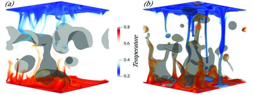
Initially, one big oil drop is placed at the center of the domain full of water. Then the oil drop breaks up into many smaller ones due to the thermally driven turbulent convection. As shown in figure 1(a), the oil phase is repelled by the oleophobic walls, whereas in figure 1(b), the oil phase is attracted by the oleophilic boundaries. This preferential wetting causes the boundary layer region to be occupied by water in the former and by oil in the latter case. These different near-wall flow structures significantly affect the heat transfer through the flow. In order to further elucidate this phenomenon, we have performed simulations with oleophobic and oleophilic walls, respectively, at various ratio from to for fixed and , as shown in figure 2(a). Since we define , for all cases, both with the oleophobic walls and with the oleophilic walls, the heat transport is enhanced as compared to the case with pure water, but the amount of enhancements for the oleophilic cases is significantly larger than for the oleophobic cases.
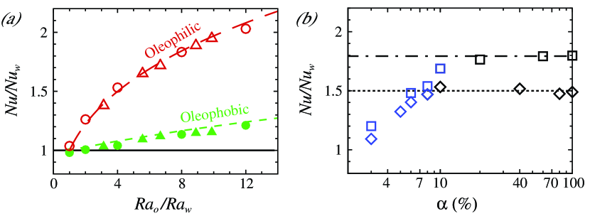
In the oleophobic case, the amount of heat transfer enhancement linearly depends on , and an enhancement of is achieved at . Based on the observation, we define an effective Rayleigh number as . With this definition, the values of Nu for the oleophobic cases well agree with the Grossmann-Lohse (GL) (Grossmann & Lohse, 2000, 2001; Stevens et al., 2013) prediction for .
Next, we examine the more intriguing case with oleophilic walls. Surprisingly, the heat transfer enhancement in the oleophilic cases dramatically increases up to at (see figure 2a), which is times larger than the enhancement in the oleophobic cases for the same parameters. It is remarkable to observe that the heat transfer efficiency can be as large as the cases with oil, despite only volume fraction of oil has been used.
One question naturally arises: what is the minimum amount of oil required for the system to transfer the maximum heat, assumed as the value for oil? To answer this question, we performed simulations with oleophilic walls for various from to at fixed and . For , Nu in the oleophilic cases increases with , while for larger than this critical value (), the heat transfer increase saturates to a value close to (the value for oil) within , as shown in figure 2(b). The same result is also achieved at and , but then with .
4 Mechanism of heat transfer enhancement
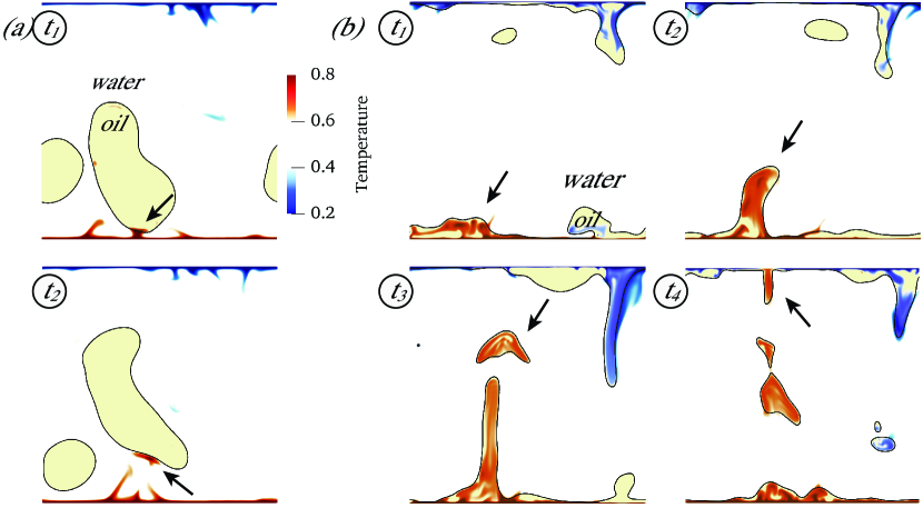
What causes the significant enhancement of heat transfer in the cases with oleophilic walls despite using only a small amount of oil? The major reason is related to the thermal plumes, which are the primary heat carrier in thermal turbulence (Ahlers et al., 2009; Lohse & Xia, 2010; Chilla & Schumacher, 2012; Shishkina, 2021). To show the effect of the thermal plumes, we visualize them in figure 3(a) for the oleophobic cases, and in figure 3(b) for the oleophilic cases. In the cases with oleophobic walls, the thermal plumes mainly stay outside the oil phase after travelling into the bulk. The reason is that surface tension prevents the entrainment of external fluid into the oil phase. The only way for the heat carried by plumes to be transported across the interface of the two immiscible fluids is via thermal diffusion, the effects of which however are sufficiently small at such high Ra.
In the oleophobic cases the thermal plumes are mainly exposed to the turbulent bulk. In contrast, in the oleophilic cases, the thermal plumes detach from the oil-rich boundary layer (figure 3b). At the same time, the oil-water interface not only keeps thermal plumes inside the oil phase, but also prevents the heat carried by plumes to be mixed into the turbulent bulk. As a result, most hot (cold) thermal plumes can travel to the opposite plate with little heat loss (gain) to the turbulent bulk as they are thermally strongly coupled to the oil phase. As shown in figure 3(b), the oil carrying the hot plumes rises up in the shape of column, then breaks up into drops, and eventually coalesces with the oil in the upper boundary layer. During this process, the oil builds up an “expressway” to transfer the heat efficiently. Thus, the heat transfer in the oleophilic cases is always significantly enhanced up to the same value as in the system with oil, and only a small amount of oil (larger than ) is required due to the strong coupling of the oil and the thermal plumes.
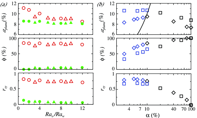
To quantitatively confirm this physical picture, we measure the amount of thermal plumes, using as thermal plumes definition condition with being the local temperature and the spatial and temporal average. In figure 4, we show the volume fraction of the total thermal plumes in the domain, , the ratio of thermal plumes in oil over the total thermal plumes, , and the correlation coefficient between the distribution of thermal plumes () and oil () in the whole domain, where the bar represents the spatial average and ranges from (no correlation) to (perfect correlation).
For the oleophilic cases, for various and fixed (figure 4a), we observe and , whereas for the oleophobic cases we always have and . This finding shows that, in the oleophilic cases, most thermal plumes indeed are strongly coupled to the oil, contrasting to the weak coupling in the oleophobic cases.
Finally how to determine the critical volume fraction of oil to achieve maximum heat transfer efficiency? In figure 4(b), we show the oleophilic cases at various and fixed and , and the critical condition for cases with Nu smaller than or close to ,
| (6) |
which well agrees with our numerical results. For (blue symbols in figure 4b), although oil and the thermal plumes are still well coupled (), there is not enough oil to generate all the plumes (), leading to Nu smaller than (figure 2b). On the other hand, for (black symbols in figure 4b), the excess amount of oil does not contribute to generating additional thermal plumes, and thus the heat transfer enhancement levels off and Nu remains close to as shown in figure 2(b). Therefore, is clearly determined by the volume of thermal plumes in the domain.
5 Conclusions and outlook
We have shown a novel way to significantly enhance the heat flux in wall-bounded thermally driven turbulence, namely by adding an oil phase (even of relatively small volume fraction) to the water and at the same time using oleophilic walls. The heat transport enhancement is brought about by the newly-found flow structure, where the thermal plumes are strongly coupled with the oil phase for cases with oleophilic walls. With the thermal plumes fully encapsulated inside the oil phase, the maximum enhancement can be obtained.
Our method and findings can easily and directly be applied and extended to other wall-bounded turbulent multiphase transport systems relevant in science and technology, way beyond thermal transport, namely to the turbulent multiphase mass or momentum transfer, such as drag in pipe or channel flow of oil-water mixtures (Pal, 1993; Roccon et al., 2021), or of bubbly flow (Lu et al., 2005; Sanders et al., 2006; Ceccio, 2010; Elbing et al., 2013; Murai, 2014), and angular momentum transfer in turbulent multiphase Taylor-Couette flow (van den Berg et al., 2007; Murai et al., 2008; van Gils et al., 2013; Spandan et al., 2018; Srinivasan et al., 2015; Hu et al., 2017; Yi et al., 2021; Bakhuis et al., 2021). The reason is that what we manipulate by the wall coating and the qualitative and quantitative choice of the two phases are the coherent structures of the turbulent multiphase flow, and these determine not only the heat transfer in turbulent flow, but also mass and momentum transfer and therefore the overall drag.
Supplementary movies
Supplementary movies are available at URL
Acknowledgments
The work was financially supported by ERC-Advanced Grant under the project no. . We acknowledge PRACE for awarding us access to MareNostrum in Spain at the Barcelona Computing Center (BSC) under the project and . This work was also carried out on the national e-infrastructure of SURFsara, a subsidiary of SURF cooperation, the collaborative ICT organization for Dutch education and research.
Declaration of interests
The authors report no conflict of interest.
References
- Ahlers et al. (2009) Ahlers, G., Grossmann, S. & Lohse, D. 2009 Heat transfer and large scale dynamics in turbulent Rayleigh-Bénard convection. Rev. Mod. Phys. 81, 503.
- Bakhuis et al. (2021) Bakhuis, D., Ezeta, R., Bullee, P. A., Marin, A., Lohse, D., Sun, C. & Huisman, S. G. 2021 Catastrophic phase inversion in high-Reynolds-number turbulent Taylor-Couette flow. Phys. Rev. Lett. 126, 064501.
- van den Berg et al. (2007) van den Berg, T. H., van Gils, D. P. M., Lathrop, D. P. & Lohse, D. 2007 Bubbly turbulent drag reduction is a boundary layer effect. Phys. Rev. Lett. 98, 084501.
- Bergman et al. (2011) Bergman, T. L., Incropera, F. P. & Lavine, A. S. 2011 Fundamentals of Heat and Mass Transfer. John Wiley & Sons, New York.
- Biferale et al. (2012) Biferale, L., Perlekar, P., Sbragaglia, M. & Toschi, F. 2012 Convection in multiphase fluid flows using lattice Boltzmann methods. Phys. Rev. Lett. 108, 104502.
- Blass et al. (2020) Blass, A., Zhu, X., Verzicco, R., Lohse, D. & Stevens, R. J. A. M. 2020 Flow organization and heat transfer in turbulent wall sheared thermal convection. J. Fluid Mech. 897, A22.
- Boussinesq (1903) Boussinesq, J. 1903 Theorie analytique de la chaleur, Vol. 2. Paris: Gauthier-Villars.
- Bushnell (2015) Bushnell, D. M. 2015 Drag reduction in nature. Annu. Rev. Fluid Mech. 23, 65–79.
- Ceccio (2010) Ceccio, S. L. 2010 Friction drag reduction of external flows with bubble and gas injection. Annu. Rev. Fluid Mech. 42, 183–203.
- Chilla & Schumacher (2012) Chilla, F. & Schumacher, J. 2012 New perspectives in turbulent Rayleigh-Bénard convection. Eur. Phys. J. E 35, 58.
- Chong et al. (2015) Chong, K. L., Huang, S.-D., Kaczorowski, M. & Xia, K.-Q. 2015 Condensation of coherent structures in turbulent flows. Phys. Rev. Lett. 115, 264503.
- Chong et al. (2017) Chong, K. L., Yang, Y., Huang, S.D., Zhong, J.-Q., Stevens, R. J. A. M., Verzicco, R., Lohse, D. & Xia, K.-Q. 2017 Confined Rayleigh-Bénard, rotating Rayleigh-Bénard, and double diffusive convection: A unifying view on turbulent transport enhancement through coherent structure manipulation. Phys. Rev. Lett. 119, 064501.
- Chung et al. (2021) Chung, D., Hutchins, N., Schultz, M. P. & Flack, K. A. 2021 Predicting the drag of rough surfaces. Annu. Rev. Fluid Mech. 53, 439–71.
- Ciliberto & Laroche (1999) Ciliberto, S. & Laroche, C. 1999 Random roughness of boundary increases the turbulent convection scaling exponent. Phys. Rev. Lett. 82, 3998–4001.
- Dhir (1998) Dhir, V. K. 1998 Boiling heat transfer. Annu. Rev. Fluid Mech. 30, 365–401.
- Ding et al. (2007) Ding, H., Spelt, P. D. M. & Shu, C. 2007 Diffuse interface model for incompressible two-phase flows with large density ratios. J. Comput. Phys. 226, 2078–2095.
- Du & Tong (2000) Du, Y. B. & Tong, P. 2000 Turbulent thermal convection in a cell with ordered rough boundaries. J. Fluid Mech. 407, 57–84.
- Elbing et al. (2013) Elbing, B. R., Mäkiharju, S., Wiggins, A., Perlin, M., Dowling, D. R. & Ceccio, S. L. 2013 On the scaling of air layer drag reduction. J. Fluid Mech. 717, 484–513.
- van Gils et al. (2013) van Gils, D. P. M., Narezo Guzman, D., Sun, C. & Lohse, D. 2013 The importance of bubble deformability for strong drag reduction in bubbly turbulent Taylor-Couette flow. J. Fluid Mech. 722, 317–347.
- Graham & Floryan (2021) Graham, M. D. & Floryan, D. 2021 Exact coherent states and the nonlinear dynamics of wall-bounded turbulent flows. Annu. Rev. Fluid Mech. 53, 227–53.
- Grossmann & Lohse (2000) Grossmann, S. & Lohse, D. 2000 Scaling in thermal convection: A unifying view. J. Fluid. Mech. 407, 27–56.
- Grossmann & Lohse (2001) Grossmann, S. & Lohse, D. 2001 Thermal convection for large Prandtl number. Phys. Rev. Lett. 86, 3316–3319.
- Guzman et al. (2016) Guzman, D. N., Xie, Y., Chen, S., Rivas Fernandez, D., Sun, C., Lohse, D. & Ahlers, G. 2016 Heat-flux enhancement by vapour-bubble nucleation in Rayleigh-Benard turbulence. J. Fluid Mech. 787, 331–366.
- Gvozdić et al. (2018) Gvozdić, B., Alméras, E. O., Mathai, V., Zhu, X., van Gils, D. P. M., Verzicco, R., Huisman, S. G., Sun, C. & Lohse, D. 2018 Experimental investigation of heat transport in homogeneous bubbly flow. J. Fluid Mech. 845, 226–244.
- Haller (2015) Haller, G. 2015 Lagrangian coherent structures. Annu. Rev. Fluid Mech. 47, 137–62.
- Holmes et al. (2012) Holmes, P., Lumley, J. L., Berkooz, G. & Rowley, C. W. 2012 Turbulence, Coherent Structures, Dynamical Systems and Symmetry. Cambridge University Press.
- Hu et al. (2017) Hu, H., Wen, J., Bao, L., Jia, L., Song, D., Song, B., Pan, G., Scaraggi, M., Dini, D., Xue, Q. & Zhou, F. 2017 Significant and stable drag reduction with air rings confined by alternated superhydrophobic and hydrophilic strips. Sci. Adv. 3 (9), e1603288.
- Huang et al. (2013) Huang, S.-D., Kaczorowski, M., Ni, R. & Xia, K.-Q. 2013 Confinement induced heat transport enhancement in turbulent thermal convection. Phys. Rev. Lett. 111, 104501.
- Jacqmin (1999) Jacqmin, D. 1999 Calculation of two-phase Navier–Stokes flows using Phase-Field modeling. J. Comput. Phys. 155, 96–127.
- Jiang et al. (2018) Jiang, H., Zhu, X., Mathai, V., Verzicco, R., Lohse, D. & Sun, C. 2018 Controlling heat transport and flow structures in thermal turbulence using ratchet surfaces. Phys. Rev. Lett. 120 (4), 044501.
- Lakkaraju et al. (2013) Lakkaraju, R., Stevens, R. J. A. M., Oresta, P., Verzicco, R., Lohse, D. & Prosperetti, A. 2013 Heat transport in bubbling turbulent convection. Proc. Nat. Acad. Sci. 110, 9237–9242.
- Liu et al. (2021a) Liu, H.-R., Chong, K. L., Wang, Q., Ng, C. S., Verzicco, R. & Lohse, D. 2021a Two-layer thermally driven turbulence: mechanisms for interface breakup. J. Fluid Mech. 913, A9.
- Liu & Ding (2015) Liu, H.-R. & Ding, H. 2015 A diffuse-interface immersed-boundary method for two-dimensional simulation of flows with moving contact lines on curved substrates. J. Comput. Phys. 294, 484–502.
- Liu et al. (2021b) Liu, H.-R., Ng, C. S., Chong, K. L., Verzicco, R. & Lohse, D. 2021b An efficient phase-field method for turbulent multiphase flows. J. Comput. Phys. 446, 110659.
- Lohse & Xia (2010) Lohse, D. & Xia, K.-Q. 2010 Small-scale properties of turbulent Rayleigh-Bénard convection. Annu. Rev. Fluid Mech. 42, 335–364.
- Lu et al. (2005) Lu, J. C., Fernandez, A. & Tryggvason, G. 2005 Drag reduction in a turbulent channel due to bubble injection. Phys. Fluids 17, 095102.
- Murai (2014) Murai, Y. 2014 Frictional drag reduction by bubble injection. Exp. Fluids 55 (7), 1773.
- Murai et al. (2008) Murai, Y., Oiwa, H. & Takeda, Y. 2008 Frictional drag reduction in bubbly Couette–Taylor flow. Physics of Fluids 20 (3), 034101.
- Ng et al. (2020) Ng, C. S., Spandan, V., Verzicco, R. & Lohse, D. 2020 Non-monotonic transport mechanisms in vertical natural convection with dispersed light droplets. J. Fluid Mech. 900, A34.
- Oberbeck (1879) Oberbeck, A. 1879 über die Wärmeleitung der Flüssigkeiten bei Berücksichtigung der Strömungen infolge von Temperaturdifferenzen. Ann. Phys. Chem. 7, 271.
- Pal (1993) Pal, R. 1993 Pipeline flow of unstable and surfactant–stabilized emulsions. AIChE J. 39, 1754–1764.
- Pirozzoli et al. (2017) Pirozzoli, S., Bernardini, M., Verzicco, R. & Orlandi, P. 2017 Mixed convection in turbulent channels with unstable stratification. J. Fluid Mech. 821, 482–516.
- van der Poel et al. (2013) van der Poel, E. P., Stevens, R. J. A. M. & Lohse, D. 2013 Comparison between two- and three-dimensional Rayleigh-Bénard convection. J. Fluid Mech. 736, 177.
- Roccon et al. (2021) Roccon, A., Zonta, F. & Soldati, A. 2021 Energy balance in lubricated drag–reduced turbulent channel flow. J. Fluid Mech. 911, A37.
- Salort et al. (2014) Salort, J., Liot, O., Rusaouen, E., Seychelles, F., Tisserand, J.-C., Creyssels, M., Castaing, B. & Chilla, F. 2014 Thermal boundary layer near roughnesses in turbulent Rayleigh-Bénard convection: Flow structure and multistability. Phys. Fluids 26, 015112.
- Sanders et al. (2006) Sanders, W. C., Winkel, E. S., Dowling, D. R., Perlin, M. & Ceccio, S. L. 2006 Bubble friction drag reduction in a high-reynolds-number flat-plate turbulent boundary layer. J. Fluid Mech. 552, 353–380.
- Shen et al. (1996) Shen, Y., Tong, P. & Xia, K.-Q. 1996 Turbulent convection over rough surfaces. Phys. Rev. Lett. 76, 908–911.
- Shishkina (2021) Shishkina, O. 2021 Rayleigh-Bénard convection: The container shape matters. Phys. Rev. Fluids 6, 090502.
- Smits et al. (2011) Smits, A. J., McKeon, B. J. & M., Ivan 2011 High-Reynolds Number Wall Turbulence. Annu. Rev. Fluid Mech. 43, 353–375.
- Soligo et al. (2021) Soligo, G., Roccon, A. & Soldati, A. 2021 Turbulent flows with drops and bubbles: What numerical simulations can tell us — Freeman Scholar Lecture. J. Fluids Eng. 143, 080801.
- Spandan et al. (2018) Spandan, V., Verzicco, R. & Lohse, D. 2018 Physical mechanisms governing drag reduction in turbulent Taylor-Couette flow with finite-size deformable bubbles. J. Fluid Mech. 849, R3.
- Srinivasan et al. (2015) Srinivasan, S., Kleingartner, J. A., Gilbert, J. B., Cohen, R. E., Milne, A. J. B. & McKinley, G. H. 2015 Sustainable drag reduction in turbulent Taylor-Couette flows by depositing sprayable superhydrophobic surfaces. Phys. Rev. Lett. 114, 014501.
- Stevens et al. (2013) Stevens, R. J. A. M., van der Poel, E. P., Grossmann, S. & Lohse, D. 2013 The unifying theory of scaling in thermal convection: the updated prefactors. J. Fluid Mech. 730, 295–308.
- Stevens et al. (2010) Stevens, R. J. A. M., Verzicco, R. & Lohse, D. 2010 Radial boundary layer structure and Nusselt number in Rayleigh-Bénard convection. J. Fluid Mech. 643, 495–507.
- van der Poel et al. (2015) van der Poel, E. P., Ostilla-Mónico, R., Donners, J. & Verzicco, R. 2015 A pencil distributed finite difference code for strongly turbulent wall–bounded flows. Computers & Fluids 116, 10–16.
- Verzicco & Orlandi (1996) Verzicco, R. & Orlandi, P. 1996 A finite-difference scheme for three-dimensional incompressible flow in cylindrical coordinates. J. Comput. Phys. 123, 402–413.
- Wagner & Shishkina (2015) Wagner, S. & Shishkina, O. 2015 Heat flux enhancement by regular surface roughness in turbulent thermal convection. J. Fluid Mech. 763, 109–135.
- Wang et al. (2020a) Wang, B.-F., Zhou, Q. & Sun, C. 2020a Vibration-induced boundary-layer destabilization achieves massive heat-transport enhancement. Sci. Adv. 6 (21), eaaz8239.
- Wang et al. (2015) Wang, Y., Shu, C., Shao, J.-Y., Wu, J. & Niu, X.-D. 2015 A mass-conserved diffuse interface method and its application for incompressible multiphase flows with large density ratio. J. Comput. Phys. 290, 336–351.
- Wang et al. (2019) Wang, Z., Mathai, V. & Sun, C. 2019 Self-sustained biphasic catalytic turbulence. Nat. Commun. 10, 3333.
- Wang et al. (2020b) Wang, Z., Mathai, V. & Sun, C. 2020b Experimental study of the heat transfer properties of self-sustained biphasic thermally driven turbulence. Int. J. Heat Mass Transf. 152, 119515.
- Xie & Xia (2017) Xie, Y.-C. & Xia, K.-Q. 2017 Turbulent thermal convection over rough plates with varying roughness geometries. J. Fluid Mech. 825, 573–599.
- Yi et al. (2021) Yi, L., Toschi, F. & Sun, C. 2021 Global and local statistics in turbulent emulsions. J. Fluid Mech. 912, A13.
- Zhong et al. (2009) Zhong, J.-Q., Funfschilling, D. & Ahlers, G. 2009 Enhanced heat transport by turbulent two-phase Rayleigh-Bénard convection. Phys. Rev. Lett. 102 (12), 124501.
- Zhu et al. (2017) Zhu, X., Stevens, R. J. A. M., Verzicco, R. & Lohse, D. 2017 Roughness-facilitated local scaling does not imply the onset of the ultimate regime of thermal convection. Phys. Rev. Lett. 119, 154501.