Destabilizing effects of edge infernal components on n = 1 resistive wall modes in CFETR 1GW steady-state operating scenario
Abstract
The stability of the resistive wall modes (RWMs) is investigated using the AEGIS code for the newly designed China Fusion Engineering Test Reactor (CFETR) 1GW steady-state operating (SSO) scenario. Here, is the toroidal mode number. Due to the large fraction of bootstrap current contribution, the profile of safety factor q is deeply reversed in magnetic shear in the central core region and locally flattened within the edge pedestal. Consequently the pressure-driven infernal components develop in the corresponding q-flattened regions of both core and edge. However, the edge infernal components dominate the RWM structure and lead to lower limits than the designed target for the CFETR 1GW SSO scenario. The edge rotation is found the most critical to the stabilization due to the dominant influence of the edge infernal components, which should be maintained above in magnitude in order for the rotation alone to fully suppress the RWM in the CFETR 1GW SSO scenario.
Keywords: CFETR, MHD stability, resistive wall modes, edge infernal components, rotation
1 Introduction
The external kink instability, which occurs when plasma exceeds the no-wall beta limit [1], can be fully suppressed by a close perfectly conducting wall up to the higher ideal-wall beta limit . Here, is the normalized plasma defined as in , where , the volume-averaged plasma pressure, the toroidal magnetic field, the plasma minor radius, and the toroidal plasma current. In reality, however, the finite wall resistivity can lead to the growth of resistive wall mode (RWM) and eventually the potential onset of plasma disruption, which is a major concern for tokamak operation and performance [2, 3].
The China Fusion Engineering Test Reactor (CFETR) project aims to bridge the gap between the experimental fusion reactor ITER [4] and the future fusion power plant DEMO [5]. During the past few years, significant progress has been made in the CFETR conceptual physics and engineering design [6, 7, 8, 9, 10, 11, 12, 13, 14, 15, 16, 17, 18]. Since 2018, a new design scenario of CFETR has been adopted with major radius and minor radius , primarily targeting the long-pause self-sustainable burning plasmas with fusion power production up to 1GW in the steady-state operation (SSO) [19].
Such SSO scenarios, in which a high bootstrap current fraction is obtained together with good energy confinement and favourable MHD stability properties, are now considered to be the most promising for future reactor scale tokamaks [20]. However, the large fraction of bootstrap current, leads to significant reduction in the magnetic shear, and thus the associated stabilization against the MHD instabilities driven by the steep pressure gradients in the transport barrier regions [21]. In this case an pressure-driven MHD mode, the infernal mode, can appear if the zero-shear, i.e. the ‘flat-q’ region has a safety factor value close to a low-order rational value, which might then destroy the barriers [22, 23, 24]. For more common cases where the flat-q region is away from rational values, the infernal components become part of the RWM and lead to lower beta limits [25].
In earlier advanced tokamak studies, more attention is drawn to the influence of the central safety factor reversal. In DIII-D [26] and JET experiments [27], it is found that the no-wall beta limit for this kind of discharge is approximately , where is the plasma inductance, whereas the ratio usually scales as for the conventional scenarios [28, 29, 30]. However, for future larger tokamaks, such as CFETR, the local bootstrap current density tends to be strong enough to form another flattened safety factor profile in the edge pedestal region. In this case the edge infernal components can develop and further destabilize the RWMs. Such a destabilizing effect of edge infernal components has been confirmed in this work, where the stability of the RWM has been analyzed using the AEGIS code [31, 32] for the CFETR 1GW SSO scenario. Consequently, stronger edge localized toroidal rotation is found to be required for the suppression of the RWM, which is above 1.5% the core Alfvénic speed for the 1GW design.
The rest of paper is organized as follows. In Sec. 2, the equilibria of the CFETR 1GW SSO scenario are briefly reviewed. In Sec. 3 the numerical scheme of AEGIS code is introduced. In Sec. 4 the stability analysis of the RWMs for the CFETR 1GW SSO scenario is reported, as well as the influence of edge infernal components on the limits. Sec. 5 evaluates the rotational stabilization effects, including those of rotation profiles. Conclusions and discussions are given in Sec. 6.
2 Equilibrium profiles and parameters of CFETR 1GW SSO scenario
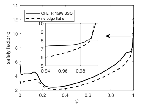
The CFETR 1GW SSO scenario is designed based on the integrated modelling in the OMFIT framework, where the EFIT code is employed to construct the MHD equilibrium used in this study [12, 13]. The main parameters are as follows: major radius , minor radius , toroidal magnetic field at magnetic axis , total plasma current , plasma inductance , the normalized beta , and the Alfvénic speed at magnetic axis . The current density profile is locally peaked at in the core and at edge (figure 1). Correspondingly, the safety factor has a reversal in magnetic shear in the central region and a flat region in the edge pedestal ranging from to . For comparison, a reference equilibrium is prepared by reducing the bootstrap current and pressure gradient in the edge pedestal region, so that the flat q profile at edge region is removed as shown in figure 1 with dashed lines. The total current and core plasma pressure are kept same as the SSO case.
3 Ideal MHD model in AEGIS code
The numerical studies in this work are carried out using the AEGIS code [31, 32]. The following linearized ideal MHD equation for toroidal plasma is solved:
| (1) |
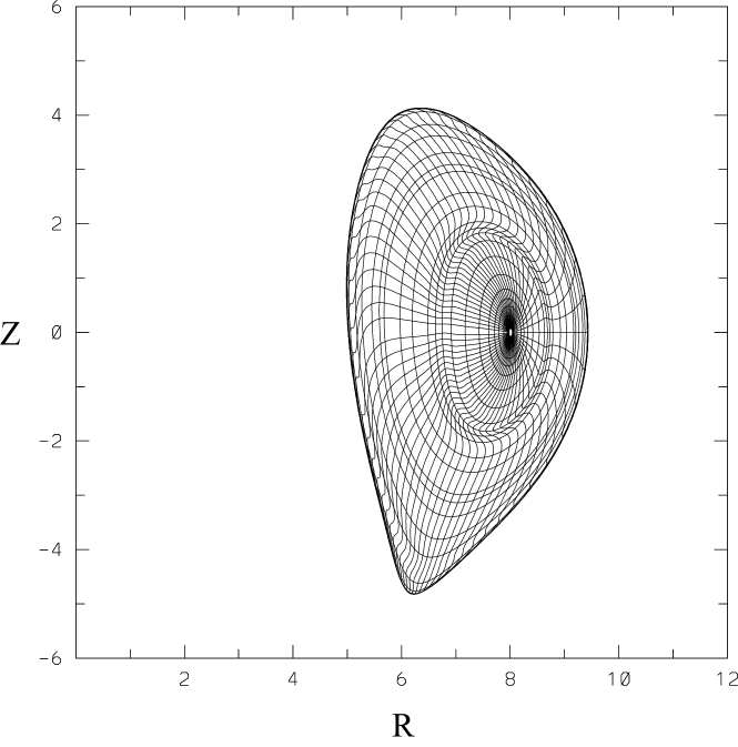
where is the mass density, the perpendicular fluid displacement, the equilibrium current density, the equilibrium magnetic field, the equilibrium pressure, , , and . The rotation effects are included mainly through the Doppler shift, with being the toroidal rotation frequency. For the subsonic rotation regime in most tokamak plasmas, the effects from centrifugal and Coriolis forces are negligible [33, 34]. In addition, since the RWM frequency in this study is much smaller than the ion acoustic wave frequency, the plasma compressibility results only in the so-called apparent mass effect through the coupling between parallel and perpendicular inertia motions [35]. Therefore, the contribution of plasma compressibility can be included by regarding as the apparent mass in the above momentum equation (1). To avoid the singularity in edge safety factor near the separatrix, the diverted equilibria of CFETR used in this study are all truncated at the poloidal flux surfaces where the safety factor value (figure 2). The conformal shaped wall is used in our AEGIS calculations.
4 Influence of edge infernal components on limits
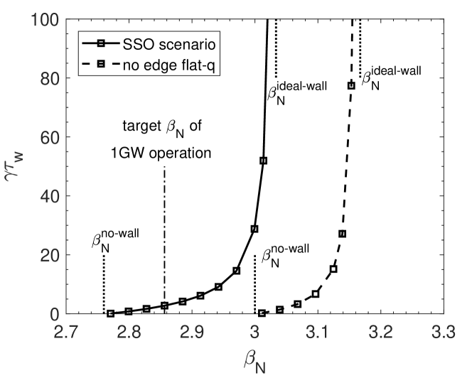
In this section we analyze the linear stability of RWM for the CFETR 1GW SSO scenario, as well as the influence of flattened q-profile in the edge pedestal region. We compare the RWM stability of the SSO scenario and the reference equilibrium in absence of the flattened q-profile near the edge as described in section 2 (figure 3), where is the resistive diffusion time of the wall, typically a few milliseconds. For the designed wall location at , we find that the reference equilibrium without the edge flattened q-profile has higher beta limits () than the SSO case (). This indicates that the edge flat q-profile is unfavourable for RWM stability. The target of CFETR 1GW SSO scenario is , which falls within the unstable RWM regime when none of the passive or active stabilizing mechanisms is taken into account.
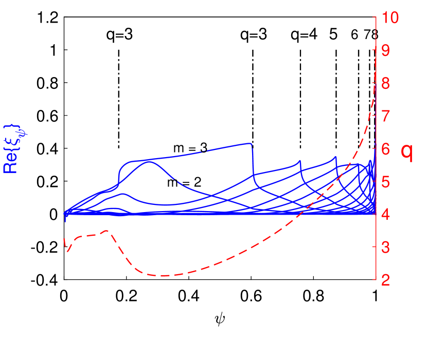
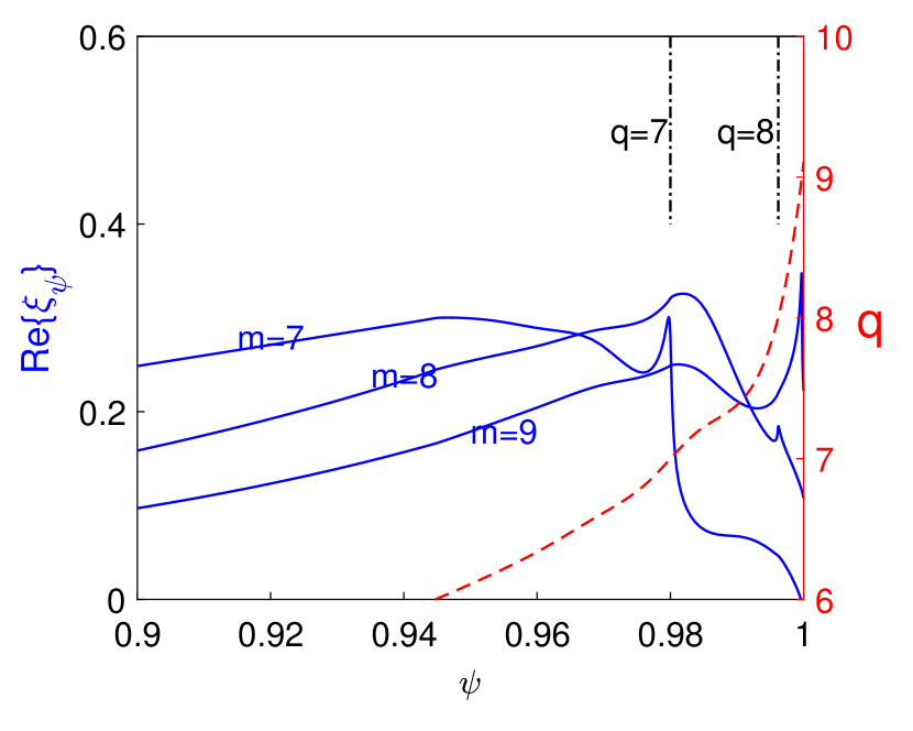
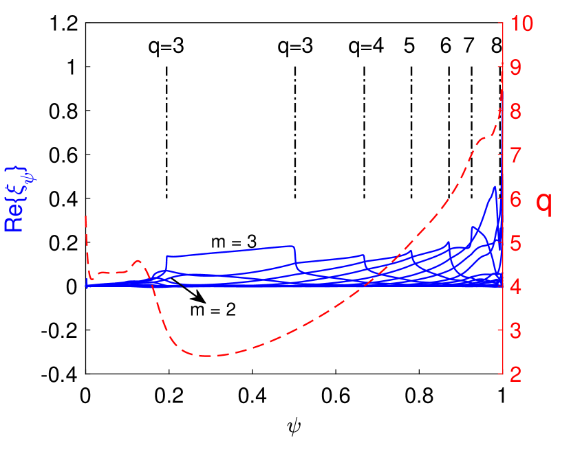
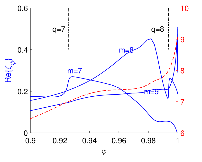
The presence of edge flat q region can significantly change the RWM mode structure. In the reference equilibrium case where the edge flattened q region is absent (figure 4), the harmonic peaks around the central flat q region. This is unusual since the minimum value is above 2 thus the harmonic is expected to be non-resonant. Meanwhile, the harmonic broadly domes over the region between the two rational surfaces with a greater amplitude. For the SSO case (figure 5), however, the edge infernal component with poloidal number becomes more dominant, even though the pressure gradient as well as the current density in the edge region is weaker than that in the central region, where the and harmonics are much reduced. In particular, unlike all other harmonics which peak around rational surfaces, the harmonic peaks in the edge flattened q region where and , which is also crucial to the rotation effects on the RWMs (see next section). Thus the edge flat q profile is more influential than the central flat q profile on the RWM mode structure and stability. This may be because that the RWM is an external MHD mode, so that the plasma current in the edge region has larger impact than that in the central region.
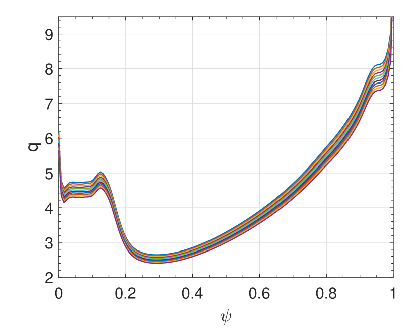
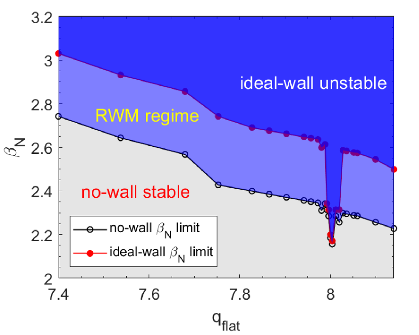
Next, the influence of safety factor value at the edge flat q region on the stability is studied. We slightly vary the total toroidal current of the SSO scenario equilibrium while keeping the shape of current density profile same. A series of equilibria with ranging from are generated as shown in figure 6(a). The stability of modes for these equilibria are evaluated. Figure 6(b) shows the no-wall and ideal-wall limits as functions of the . One can see that both limits dramatically drop when , whereas apart from that they gradually decrease with . Moreover, both limits become nearly identical at , indicating the complete loss of wall stabilization. Note that in this case, the eigenfunction becomes delta-function-like and peaks at the resonance point for a single Fourier component, which can be identified as the infernal mode. Thus, the presence of the edge flat q region may subject the SSO scenario to the external instability even at a considerably low .
5 Rotational stabilization effects on RWM with edge infernal components
In this section, we evaluate the stabilization effects on RWM due to toroidal plasma rotation with three types of radial profiles: the uniform rotation profile, the radially descent profile, and the Gaussian rotation profile.
5.1 Uniform profile
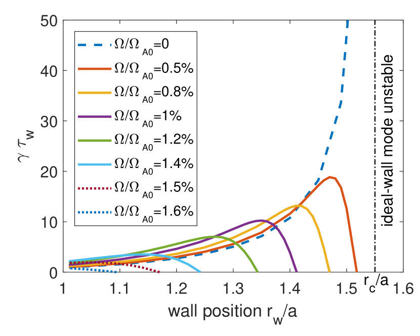
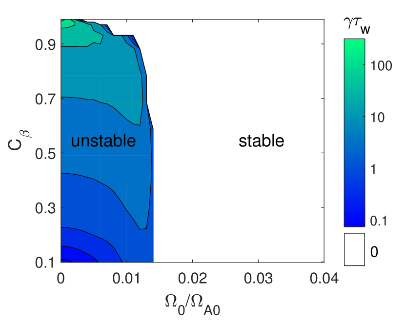
We first compare the RWM growth rate variation over the first-wall location for a range of rotation frequencies accessible in the SSO scenario with the target (figure 7(a)). In absence of rotation, the RWM growth rates tend to infinity near the critical wall position . In presence of rotation, the RWM growth rates initially increase with the wall radius, but then drop quickly to zero beyond a certain wall radius . Since , as a result, a ‘stable window’ opens up between and the critical wall position . The stronger the rotation, the wider the ‘stable window’ , which can be used as a measurement of the rotational stabilization effects. For the designed wall position , the RWM can be fully suppressed by a rotation frequency of , where is the Alfvénic frequency defined as . Figure 7(b) shows the RWM stability diagram in the 2D parameter space (, ) with the wall position . Here, is a scaling factor ranging from between the two limits. It is found that a uniform rotation with provides sufficient stabilization on RWM for all achievable .
5.2 Radially descent profile
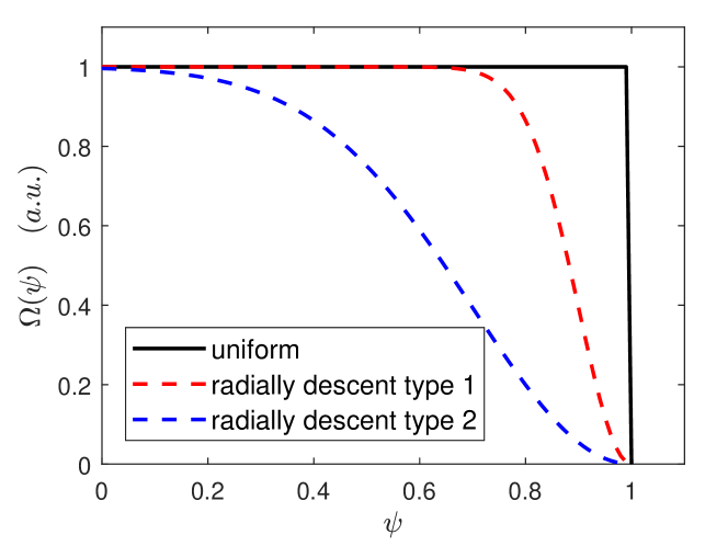
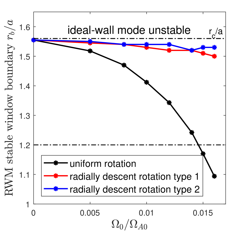
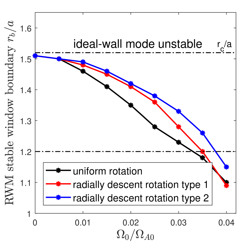
In this subsection, we consider a toroidal rotation with nearly uniform radial profile in the region of to and rapidly descent profile in the region of to , which is similar to the design for ITER [36]; and a rotation with gradually descent profile in the entire radial direction, which is similar to the design for CFETR [13]. The rotation profiles are plotted as ‘type 1’ and ‘type 2’ in figure 8. The reference equilibrium without the edge flat q region is also considered for comparison (figure 9). With radially descent profiles, rotation can barely open up the ‘stable window’ for the SSO case, whereas the ‘stable window’ can readily open up and become wider with larger rotation frequency in the reference case. This suggests that the toroidal rotation with radially descent profile may not be effective or sufficient for stabilizing the RWM in the SSO scenario due to the strongly destabilizing presence of the edge infernal mode component localized in the edge flat q region.
5.3 Gaussian profile
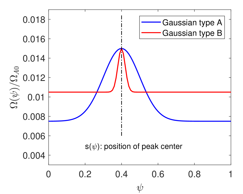
We further consider the Gaussian shaped rotation profiles as shown in figure 10(a) and parameterized as follows,
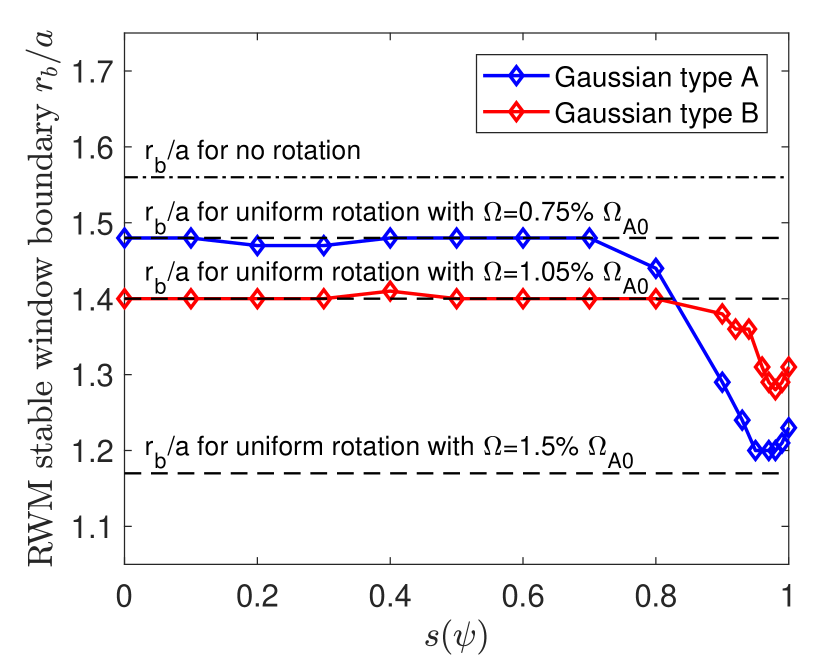
where the peak location ranges from 0 to 1. We investigated the effects of these rotation profiles on RWM ‘stable window’ for the CFETR 1GW SSO scenario. Figure 10(b) shows the lower boundary of the RWM ‘stable window’ as functions of rotation peak position . When the rotation profiles are peaked in the core region (i.e. ), their stabilizing effects are not different from the uniform rotation with the same corresponding off-peak rotation frequency, since they share the same RWM ‘stable window’, respectively. However, when the peak of the profile moves to plasma edge, the boundaries of the ‘stable window’ change significantly. The maximum stabilizing effects are obtained when , where the edge infernal component peaks (figure 5). When the edge peaked rotation profile is also sufficiently broad to cover the region of edge flat q-profile or infernal mode component, a peak rotation frequency above can fully stabilize the RWM in the CFETR 1GW SSO scenario.
6 Summary and Discussions
In summary, we have studied the RWM stability in the CFETR 1GW SSO scenario using the AEGIS code. Due to the large bootstrap current contribution, such an SSO scenario has a deep safety factor reversal in the core region and a flat q profile in the edge region, corresponding to the internal and external transport barriers, respectively. As a consequence, the infernal mode components develop in both core and edge regions. The edge infernal component dominates the destabilizing effects for RWMs, which lower the limits and render the RWM unstable in the CFETR 1GW SSO scenario.
The RWMs can be fully suppressed by uniform rotation with frequency above . Due to the influence of the edge infernal components, it is the edge rotation that mainly contributes to the stabilization effect. Thus an edge localized toroidal rotation with a sufficiently broad profile and its peak rotation frequency maintained at above can fully stabilize the RWMs in the CFETR 1GW SSO scenario. However, a robust control of RWM in CFETR SSO may require a full account of all other possible stabilizations from kinetic effects, as well as the active stabilizations from the feedback control coil system, which should be evaluated in other and future work.
7 References
References
- [1] Troyon F, Gruber R, Saurenmann H, Semenzato S and Succi S 1984 Plasma Physics and Controlled Fusion 26 209–215
- [2] Freidberg J 1987 Ideal Magnetohydrodynamics (Plenum Press, New York)
- [3] Chu M S and Okabayashi M 2010 Plasma Physics and Controlled Fusion 52 123001
- [4] Aymar R, Barabaschi P and Shimomura Y 2002 Plasma Physics and Controlled Fusion 44 519–565
- [5] Zohm H, Angioni C, Fable E, Federici G, Gantenbein G, Hartmann T, Lackner K, Poli E, Porte L, Sauter O, Tardini G, Ward D and Wischmeier M 2013 Nuclear Fusion 53 073019
- [6] Wan B, Ding S, Qian J, Li G, Xiao B and Xu G 2014 IEEE Transactions on Plasma Science 42 495–502
- [7] Song Y T, Wu S T, Li J G, Wan B N, Wan Y X, Fu P, Ye M Y, Zheng J X, Lu K, Gao X, Liu S M, Liu X F, Lei M Z, Peng X B and Chen Y 2014 IEEE Transactions on Plasma Science 42 503–509
- [8] Chan V, Costley A, Wan B, Garofalo A and Leuer J 2015 Nuclear Fusion 55 023017
- [9] Mao S, Guo Y, Peng X, Luo Z, Xiao B, Song Y, Yao D, Zhu S and Ye M 2015 Journal of Nuclear Materials 463 1233 – 1237
- [10] Wan Y, Li J, Liu Y, Wang X, Chan V, Chen C, Duan X, Fu P, Gao X, Feng K, Liu S, Song Y, Weng P, Wan B, Wan F, Wang H, Wu S, Ye M, Yang Q, Zheng G, Zhuang G and and Q L 2017 Nuclear Fusion 57 102009
- [11] Li J and Wan Y 2019 Journal of Fusion Energy 38 113–124
- [12] Jian X, Chen J, Chan V S, Zhuang G, Li G, Deng Z, Shi N, Xu G, Staebler G M and Guo W 2017 Nuclear Fusion 57 046012
- [13] Chen J, Jian X, Chan V S, Li Z, Deng Z, Li G, Guo W, Shi N, Chen X and Team C P 2017 Plasma Physics and Controlled Fusion 59 075005
- [14] Liu L, Kessel C, Chan V, Guo Y, Chen J, Jian X, Mao S and Ye M 2018 Nuclear Fusion 58 096009.1–096009.18
- [15] Li Z Y, Chan V, Zhu Y R, Jian X, Chen J L, Cheng S K, Zhu P, Xu X Q, Xia T Y, Li G Q, Lao L, Snyder P and and X G W 2018 Nuclear Fusion 58 016018
- [16] Cheng S, Zhu P, Banerjee D and Yan X 2019 Plasma Physics and Controlled Fusion 61
- [17] Ren Z Z, Chen Y, Fu G and Wang Z X 2019 Nuclear Fusion 60 016009
- [18] Han R, Zhu P, Banerjee D, Cheng S, Yan X, Zheng L and Team C P 2020 Plasma Physics and Controlled Fusion 62 085016
- [19] Zhuang G, Li G, Li J, Wan Y, Liu Y, Wang X, Song Y, Chan V, Yang Q, Wan B, Duan X, Fu P and and B X 2019 Nuclear Fusion 59 112010
- [20] Joffrin E 2007 Plasma Physics and Controlled Fusion 49 B629–B649
- [21] Peeters A G 2000 Plasma Physics and Controlled Fusion 42 B231–B242
- [22] Manickam J, Pomphrey N and Todd A 1987 Nuclear Fusion 27 1461–1472
- [23] Zheng L J, Kotschenreuther M T and Valanju P 2013 Physics of Plasmas 20 012501
- [24] Dong G Q, Liu Y Q, Wang S, Zhang N, Yu D L, Liu Y and Wang Z R 2017 Physics of Plasmas 24 112510
- [25] Zheng L, Kotschenreuther M and Valanju P 2017 Nuclear Fusion 57 066029
- [26] Reimerdes H, Garofalo A M, Jackson G L, Okabayashi M, Strait E J, Chu M S, In Y, La Haye R J, Lanctot M J, Liu Y Q, Navratil G A, Solomon W M, Takahashi H and Groebner R J 2007 Physical Review Letters 98(5) 055001
- [27] Reimerdes H, Hender T C, Sabbagh S A, Bialek J M, Chu M S, Garofalo A M, Gryaznevich M P, Howell D F, Jackson G L, La Haye R J, Liu Y Q, Menard J E, Navratil G A, Okabayashi M, Pinches S D, Sontag A C, Strait E J, Zhu W, Bigi M, de Baar M, de Vries P, Gates D A, Gohil P, Groebner R J, Mueller D, Raman R, Scoville J T and Solomon W M 2006 Physics of Plasmas 13 056107
- [28] Lao L L, Taylor T S, Chu M S, Chan V S, Ferron J R and Strait E J 1992 Physics of Fluids B: Plasma Physics 4 232–240
- [29] Strait E J 1994 Physics of Plasmas 1 1415–1431
- [30] Taylor T S, Strait E J, Lao L L, Mauel M, Turnbull A D, Burrell K H, Chu M S, Ferron J R, Groebner R J, La Haye R J, Rice B W, Snider R T, Thompson S J, Wròblewski D and Lightly D J 1995 Physics of Plasmas 2 2390–2396
- [31] Zheng L J, Kotschenreuther M and Chu M S 2005 Physical Review Letters 95(25) 255003
- [32] Zheng L J and Kotschenreuther M 2006 Journal of Computational Physics 211 748 – 766
- [33] Waelbroeck F L and Chen L 1991 Physics of Fluids B: Plasma Physics 3 601–610
- [34] Zheng L J, Chu M S and Chen L 1999 Physics of Plasmas 6 1217–1226
- [35] Greene J M and Johnson J L 1962 The Physics of Fluids 5 510–517
- [36] Chrystal C, Grierson B A, Staebler G M, Petty C C, Solomon W M, deGrassie J S, Burrell K H, Tala T and Salmi A 2017 Physics of Plasmas 24 056113