Latency of Concatenating Unlicensed LPWAN with Cellular IoT: An Experimental QoE Study
Abstract
Developing low-power wide-area network (LPWAN) solutions that are efficient to adopt, deploy and maintain are vital for smart cities. The poor quality-of-service of unlicensed LPWAN, and the high service cost of LTE-M/NB-IoT are key disadvantages of these technologies. Concatenating unlicensed with licensed LPWANs can overcome these limitations and harness their benefits. However, a concatenated LPWAN architecture will inevitably result in excess latency which may impact users’ quality-of-experience (QoE). To evaluate the real-life feasibility of this system, we first propose a concatenated LPWAN architecture and experimentally measure the statistics of end-to-end (E2E) latencies. The concatenated delay margin is determined by benchmarking the latencies with different LPWAN architecture schemes, namely with unlicensed IoT (standalone LoRa), cellular IoT (standalone LTE-M), and concatenated IoT (LoRa interfaced with LTE-M). Through extensive experimental measurement campaigns of data points of E2E latencies, we show that the excess delay due to LPWAN interfacing introduces on average less than milliseconds. The proof-of-concept results suggest that the latency for concatenating unlicensed LPWAN with cellular IoT is negligible for smart city use cases where human perception and decision making is in the loop.
Index Terms:
LPWAN, Cellular IoT, Latency, QoE, Smart Cities.I Introduction
IoT applications for enhanced and massive machine type communications (eMTC/mMTC) is growing at an unprecedented rate, empowering connectivity in various fields such as healthcare, agriculture, climate and smart city applications. To support communications for various IoT use cases, low-power wide-area network (LPWAN) technologies are used where appropriate to transmit small payloads at long distances with minimal power consumption.
Traditional LPWAN, such as LoRa/LoRaWAN and Sigfox, operate in unlicensed radio spectrum. While freely available on ISM bands, unlicensed IoT is prone to RF interference and poor quality-of-service (QoS). On the other hand, licensed IoT offers a more reliable communication as it depends on cellular infrastructure deployed with careful network planning. As a consequence, the industry is complementing the IoT ecosystem with licensed LPWAN for eMTC and mMTC applications. Today, this is done through the use of LTE-M and NB-IoT technologies defined by 3GPP rel. 13-14 (4G), and rel. 15-16+ (5G). Granted, licensed IoT will require regular subscription for each sensor node with a mobile network operator, and this is a costly solution for large-scale smart city deployment.
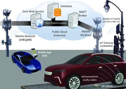
To overcome these limitations, we propose a concatenated network architecture that harnesses the advantages of both unlicensed and licensed LPWAN. Consider the smart parking application shown in Fig. 1, where large or massively deployed unlicensed IoT sensors detect status changes in parking spaces and backhauls aggregated data via a number of cellular IoT nodes to the cloud for user access. Although this concatenated LPWAN architecture combines affordability and reliability together, the main drawback is the added latency due to interfacing and data hopping of information packets.
In literature, various contributions have studied the throughput, range, and power of unlicensed (e.g., [1, 2, 3]) and licensed IoT (e.g., [4, 5, 6]). Furthermore, a monitoring system was tested by combining NB-IoT and LoRa [7], and a hybrid 3G-LoRa-Sigfox for power grid monitoring was verified with legacy technologies [8]. While these works provide valuable insights, a proof-of-concept (PoC) and quality of experience (QoE) assessment with end-to-end (E2E) latency measurement for concatenated LPWAN architecture is yet to be explored.
In this paper, we propose a concatenated network architecture and protocols with unlicensed LPWAN and cellular IoT over a private core infrastructure. Due to the availability of 3GPP LTE Cat M1 service by local mobile operators, we implement the architecture with LoRa and LTE-M networks. Through E2E latency measurement campaigns, data points are experimentally collected and statistically analyzed for standalone and concatenated LPWAN architectures [9]. Data-driven discussions and remarks on the feasibility of a concatenated LPWAN architecture to achieve a target QoE for smart city applications with users in the loop is also provided.
II Network Architecture
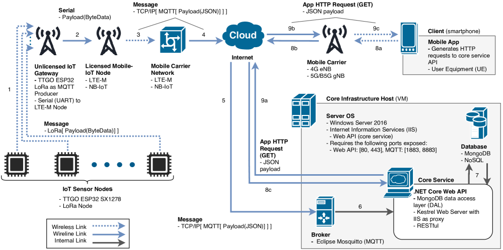
The E2E architecture from in-field sensing to remote detection is based on three major steps: (i) uplink communications, (ii) cloud and core infrastructure, and (iii) mobile end-user application. Our proposed concatenated LPWAN architecture with different possible IoT technology choices is shown in Fig. 2. As seen first, information packets from large or massive amount of sensor nodes are aggregated by fewer IoT gateways. Then, the aggregated data from gateways is relayed to cellular IoT nodes for uplink communication to a mobile carrier network. The data from packets is then processed, stored, and made available to mobile clients from the core infrastructure residing in either a public or private cloud. An explanation of the various sub-components of this concatenated architecture is provided below.
II-A Uplink Communications
Starting with IoT sensor nodes, this subsection covers communications up to the public cloud.
1 Data aggregation of IoT sensors
Payload construction by a sensor IoT node begins after new sensing data is detected and produced. The payload is then split into byte segments and transmitted over radio on unlicensed spectrum via LoRa systems. Developed by Semtech, LoRa is a physical (PHY) and data link (MAC) layers protocol utilizing chirp spread spectrum modulation to transmit between and kbps over large distances with minimal power consumption. In North America, LoRa operates on the unlicensed to MHz ISM frequency band. Often paired with a LoRa system is LoRaWAN, a network layer protocol used to route data from LoRa nodes to a gateway and then to the internet. From end-user device to network server and at the application level, LoRaWAN uses two layers of 128 bits AES encryption [10].
2 Gateway to cellular IoT communication
Once the transmitted sensor payloads are received by an unlicensed gateway, they are first extracted from the LoRa protocol and then sent via a serial protocol to a licensed cellular IoT radio within the same device package. At this same point, the payload is wrapped in a lightweight messaging protocol such as MQTT in preparation for IP routing.
3 Transmission from cellular IoT to mobile carrier
This communication serves as the backhaul, forwarding payload via licensed cellular IoT. LTE Cat M1 or NB-IoT devices will then uplink to nearby eNB or gNB cell towers to connect to the rest of the mobile carrier network. The concatenated architecture of Fig. 2 is compatible and it can be adapted with both LTE-M and NB-IoT. In reality, the regional availability of cellular IoT by mobile operators will dictate which of these licensed LPWAN options is accessible by users. In general, NB-IoT service is widely available in Asia and Europe. Currently in North America, LTE-M service is more common, and NB-IoT is still in its early stages. Developed by 3GPP rel. 13+ for IoT applications, LTE-M operates on closed network servers and on several licensed frequencies (e.g., bands 2, 4, 5, 12 and 13 in Canada). This technology uses time division duplex and a peak data rate of 1 Mbps for uplink and downlink with MHz bandwidth. Since each cellular IoT device requires a SIM card and service contract, large-scale implementation of LTE-M is expensive. The proposed concatenated architecture alleviates the need for a costly deployment of large or massive volume of cellular IoT nodes through system interfacing with unlicensed LPWAN sensors.
4 Communication from evolved packet core to cloud
The IP uplink is made possible by the service provider which routes data from the mobile carrier network through wireline comprising of hybrid coaxial fiber. Eventually, data packets reaching the evolved packet core are forwarded to the cloud for computation and transmission.
II-B Cloud and Core Infrastructure
IoT sensor payloads are transferred through the internet to the core infrastructure for processing.
5 TCP/IP routing to core infrastructure
The communication involves routing from the carrier network through IP communication to a broker hosted by a cloud infrastructure. This architecture identifies IoT sensor nodes and gateway technology as part of the private cloud receiving MQTT payloads from concentrated LoRa traffic. A private core infrastructure could be substituted by a public cloud (e.g., Azure or AWS IoT). Rather than involved elaborate setups, public cloud solutions facilitate insights into the analytics of sensor payloads. For instance, Azure Monitor and AWS Cloud Watch both enable resource metric and telemetry collection while visualizations are generated by Microsoft Power BI and AWS Quicksight. Although developers may invest effort into implementing these services for robust security, cloud native IoT platforms deliver them automatically as pay-per-use subscriptions which often scale quickly [11]. The cost and offering implications make public clouds viable for corporate IoT roll-out with private clouds more suitable and secure for testing and research.
6 Delivering data from message broker to core service
To address high traffic from large-scale IoT sensors, MQTT messages are ingress by a broker such as Eclipse Mosquitto. Similar to publisher/subscriber paradigms, the broker delivers sensor payload to the core service via a subscribed channel/topic. The core service is an application that serves three main objectives: business logic processing, data access layer (DAL), and application programming interface (API). They all can be decoupled for a service-oriented architecture.
7 Storing sensor information in core service database
The nature of IoT oftentimes results in unstructured data, which is best suited for NoSQL data stores that can leverage a variety of data models from tables to documents. The key benefit of going with document-based database models would be alignment with common and modern web formats and DALs. One such technology that achieves this is MongoDB, where documents are stored in a superset of JSON known as BSON.
II-C Mobile Application and Core Service
The consumption of IoT sensor data by clients is identified in this final subsection of the architecture.
8 Mobile client request
In this concatenated LPWAN network architecture, the user equipment (UE) performs an action requesting data over Hypertext Transfer Protocol (HTTP). This request is sent through the UE’s connected network, eventually reaching the internet. Once it reaches the core services, the request is routed to the core service API.
9 Core service response
The core service follows the representational state transfer (REST) architecture for web service communications. RESTful APIs are ideal over simple object access protocol (SOAP) and others since it not only provides clear separation between data producers and consumers, but it is also data format agnostic. This enables developers to create highly compatible APIs to consume and deliver a variety of IoT sensor data with minimal coupling to UE’s application. While REST is modern, it is unsuitable and often unnecessary for certain applications. For instance, when a core service must constantly stream data to a client or vice-versa, a persistent bi-directional communication channel should be established. WebSocket is one protocol that serves this purpose, creating a TCP duplex connection that enables message pooling without the need to wait for a response like HTTP [12].
III Experimental Setup and Methodology
As a critical key performance indicator (KPI) for QoE assessment, we experimentally evaluate a precise E2E latency for the concatenated LPWAN architecture with LoRa and LTE-M networks. Using the architecture detailed in Sec. II, we divide the E2E latency into several components based on where we have measurable insight with data entry and exit of architecture subsystems to capture timing information. These components are defined as follows:
-
•
: uplink communication latency of IoT sensor payload to the core infrastructure (Fig. 2, links 1 to 7).
-
•
: queuing delay in the core service database before client request (Fig. 2, core infrastructure).
-
•
: mobile client request and resulting core service downlink response latency (Fig. 2, links 8 and 9).
-
•
: internal latency for graphical user interface (GUI) rendering at the UE (Fig. 2, client’s application).
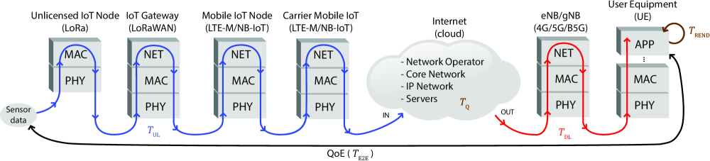
For further clarification, the time measures are also shown in Fig. 3 as the sensing packets pass across different OSI layers and network components of the architecture. The resultant E2E latency is represented as the sum of the time measures; namely
| (1) |
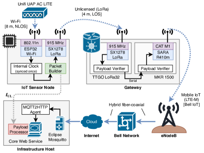
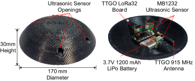
The experimental setup that implements the proposed concatenated LPWAN architecture is detailed in Fig. 4, where the key specifications for the communication system and network equipment considered for the data collection campaign are listed in Table I. The PoC experiment was conducted in an outdoor parking lot in the suburbs of the Greater Toronto Area using the smart parking LPWAN sensor node shown in Fig. 5. This particular sensor is intended for efficient deployment and use at the center of a 2-by-2 parking lot configuration. Contained within this integrated unit is a TTGO LoRa32 microcontroller that processes data from four MB1232 ultrasonic sensors. We designed the sensor with openings on the top-side of the casing where the angles of the port holes was determined based on North American parking lot dimensions with each ultrasonic sensor pointing towards the center of a parking spot.
During initialization, the LPWAN sensor node with TTGO ESP32 LoRa development board establishes a GHz radio link connectivity once over IEEE 802.11n. Time is synchronized via network time protocol (NTP) server before disconnecting. LoRa packets of bytes are then built with a bytes label, 10 bytes Unix timestamp, 15 bytes static padding for sensor data fields, including device identification and token-based authentication (auth token), and finally with a null terminator byte to indicate the end of the packet. Timing for begins immediately once a new data packet is transmitted by a LoRa sensor node. To gather a large sample size of latency measurements, the process is repeated every 500 ms, with data flowing at a rate of .
Another TTGO ESP32 development board is used as a LoRa gateway that scans for a payload of 28 bytes and validates its integrity against a 2 bytes label. Once validated, the payload is sent serially to the MKR 1500 which assembles an MQTT UDP packet. The MKR transmits the packet via LTE-M through Bell Canada’s network to its final destination at the core infrastructure host that runs the Eclipse Mosquitto broker. Subscribed to this channel/topic is a custom lightweight service agent MQTT2HTTP forwarding to the core service API. Measurement of concludes when the payload is received at the core service, its timestamp difference calculated, and a persistent entry written to MongoDB database.
| hardware equipment | CPU/MPU | storage | radio access |
|---|---|---|---|
| TTGO LoRa32 | ESP32 | kB | MHz, Mbps |
| (LoRa/LoRaWAN) | DOWDQ6 | SRAM | dBm (Tx), dBm (Rx) |
| MKR NB 1500 | SAMD21 | kB | Bands 4, 5, 12, kbps (UL) |
| (LTE Cat M1) | Cortex | SRAM | dBm (Tx), dBm (Rx) |
| HPE ProLiant DL380 G5 | Intel Xeon | GB disk | Broadcom NC373i |
| (core infrastructure) | E5440 | GB RAM | Gigabit server adapter |
| Samsung Galaxy S7 | Exynos 8890 | GB flash | GSM/HSPA/LTE |
| (mobile client) | Octa SoC | GB RAM | IEEE 802.11n, 2.4/5 GHz |
Meanwhile, the core infrastructure host is a Windows Server virtual machine (VM). This VM runs on as ESXi 5.5 hypervisor installed bare-metal onto an HP Proliant DL380 G5 rack-mount server. Key software running on this VM are MongoDB (v4.2.3), Internet Information Services (v10.0), Eclipse Mosquitto (v1.6.11), and MQTT2HTTP (v0.1). The UE is a Samsung Galaxy S7 G930W8 running the latest supported build of Android 8.0 Oreo with TouchWiz GUI.
Continuing to , a GET method is written for the core service API which responds with a 28 bytes JSON payload. This method is invoked via barebones flutter application running on the client timing request until core service response. Finally, the measurement of is obtained as time taken to render a data-driven GUI component on the mobile application. We designed the mobile app to display the availability of parking spaces (see Fig. 1) in a specific lot of Sheridan’s Davis campus that features 183 spots. The application redraws equiangular polygons in Flutter Maps onto a MapBox PolygonLayer on the client UE’s GUI to illustrate the parking availability and information.
Overall, the latency measurements were collected during business hours, i.e., 9:00 to 17:00 on weekdays, over a period of two weeks. For benchmarking purposes, the experiment was repeated twice more with similar parameters for standalone LoRa connected through WLAN to the internet service provider, and LTE-M through Bell’s cellular network.
IV Experimental Results and Analysis
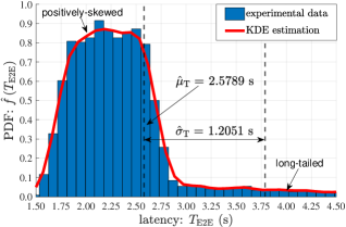
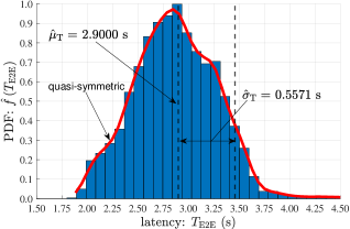
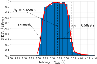
In order to yield reliable statistics, in excess of E2E latency measurements are experimentally collected for the standalone and concatenated LPWAN architecture schemes. Using the dataset that is openly available in [9], and examining the order of magnitude of the time measures in (1), we notice that . The probability density function (PDF) of the aggregated E2E latency for unlicensed IoT (LoRa), cellular IoT (LTE-M), and concatenated LPWAN (LoRA interfaced with LTE-M) are respectively plotted in Fig. 6. The histogram plots are obtained with a statistically significant sample size of data points for each LPWAN scheme, and bins is considered for distribution accuracy (see blue histogram bars in Fig. 6).
In addition, the empirical distributions of are approximated analytically using the kernel density estimation (KDE),
| (2) |
where a Gaussian kernel function is used (see red curves in Fig. 6). The bandwidth (BW) of KDE is determined using Silverman’s rule, i.e., , where is the median absolute deviation (MAD), with representing the median of the finite set , for E2E latency measurements. MAD is a variation metric that provides a more robust estimation for the standard deviation (SD) through greater resiliency to outliers and extreme values within the dataset. As evident in Fig. 6, the KDE closely match the experimental plots for the three LPWAN architecture schemes, where is the SD for the smooth KDE curves.
The KDE can be used to analytically characterize the randomness of the underlying E2E experimental latencies, which is paramount in predicting and measuring end-users’ QoE. A larger sample size of latency measurements from PoC experiments will certainly yield a more robust analytical predictor that can be used to randomly generate reliable E2E latencies for performance evaluation of networks.
The statistics and estimation parameters from the density plots are shown in Table II, where the sample mean and SD (see vertical lines in Fig. 6) are accordingly evaluated by
| (3) |
From the results, we observe that the concatenated LPWAN architecture has an excess latency that is on average ms more than the standalone cellular IoT with LTE-M communications. In fact, the excess delay was expected as a consequence of interfacing unlicensed LPWAN with cellular IoT, as this introduces more data transmission hops on the path to the core service. Although the comparison of the concatenated scheme to cellular IoT is more relevant, it is still worthwhile to notice that the excess latency with LoRa over WLAN is nearly double the average value with LTE-M.
| LPWAN | mean | SD | MAD | KDE BW | SD of KDE |
|---|---|---|---|---|---|
| schemes | (s) | (s) | (s) | (s) | |
| LoRa/LoRaWAN | |||||
| 3GPP LTE Cat M1 | |||||
| LoRa + LTE-M |
Moreover, it is interesting to remark that the spread of LPWAN schemes with cellular IoT is approximately half that of unlicensed IoT with LoRa technology. This essentially means that E2E latencies with cellular IoT, irrespective of being standalone or concatenated, have lower entropy. In other words, these LPWAN networks that are dependent on mobile operators have values that are more predictable.
The shape of the E2E latency PDFs in Fig. 6 are also unique from one LPWAN network to the other. In essence, this gives us a signature for the latency profile of each LPWAN architecture. In particular, unlicensed IoT exhibits a long-tailed distribution that is positively skewed with a left-leaning curve. On the other hand, cellular IoT and concatenated LPWAN have E2E latency distributions that are more symmetrical, where the former is more dispersed than the latter.
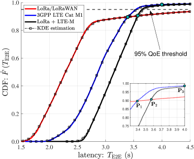
To assess the feasibility of an LPWAN architecture to meet a certain target QoE, it is insightful to also look at the cumulative distribution function (CDF) of the particular KPI under study. As plotted in Fig. 7 for the three LPWAN schemes, the CDF is determined by . The E2E latency probability that LPWAN sensors data is received at the application layer of an edge user from the cloud can be used to assess the QoE performance. This can be determined from the CDF, i.e., , where is the random variable for latency and is the stipulated E2E target delay.
Meanwhile, we notice that the CDF plots of KDE (see square marked plots in Fig. 7) almost perfectly overlap the curves from experimental measurements. From the plots, we also identify intersection points that help us in distinguishing the different regimes of the probability distributions of E2E latency for the LPWAN architectures. These values are: ; ; and . This means that if s, unlicensed LPWAN outperforms cellular IoT. For example, if a s E2E latency is accepted, LoRa surpasses with nearly likelihood of meeting the latency target, while standalone LTE-M and concatenated LPWAN achieve and respectively. On the other hand, if for certain smart city use cases an extra second is tolerated, then, LTE-M and concatenated LPWAN outperform standalone LoRa by a factor of . In this situation, LTE-M and concatenated LPWAN both achieve the same latency performance of , irrespective of excess latency. However, the minimum QoE threshold for user satisfaction should generally aim to satisfy a performance of for real-life applications (see horizontal line in Fig. 7).
V Conclusion
In this paper, we proposed a concatenated LPWAN architecture over a private core infrastructure that interfaces LoRa with cellular IoT in order to mitigate poor QoS and costly service plans. Through precise QoE assessment, E2E latency measurements were experimentally recorded for the concatenated architecture, and the data was compared to standalone licensed and unlicensed LPWANs. The statistics from the density functions reveal that the proposed concatenated LPWAN added, on average, an excess latency of and when compared to standalone LoRa and LTE-M. Nevertheless, such milliseconds of E2E excess latency is humanly insignificant for use cases where perception is needed. More importantly, we also found that concatenated LPWAN outperforms unlicensed IoT by roughly s at the typical QoE threshold of for users’ satisfaction. Overall, this experimental study suggests that a concatenated LPWAN is technically feasible and offers an affordable alternative for real-world smart city deployment.
Acknowledgments
This research work is supported, in part, by Sheridan’s Research and Creative Activities Growth Grant, and by Bell Canada’s IoT Solutions for eMTC (3GPP LTE Cat M1) network access and services. The authors are also grateful to ENCQOR-5G program for testbed access. They also would like to acknowledge Keysight Technologies for research discussions regarding implementation and measurements.
References
- [1] D. Magrin, M. Centenaro, and L. Vangelista, “Performance evaluation of LoRa networks in a smart city scenario,” in Proc. of IEEE Intl. Conference on Communications (ICC), 2017.
- [2] E. M. Rochester, A. M. Yousuf, B. Ousat, and M. Ghaderi, “Lightweight carrier sensing in LoRa: Implementation and performance evaluation,” in Proc. of IEEE Intl. Conference on Communications (ICC), 2020.
- [3] A. Furtado, J. Pacheco, and R. Oliveira, “PHY/MAC uplink performance of LoRa class A networks,” IEEE Internet of Things Journal, vol. 7, no. 7, pp. 6528–6538, 2020.
- [4] A. H. El Fawal, M. Najem, A. Mansour, F. Le Roy, and D. Le Jeune, “CTMC modelling for H2H/M2M coexistence in LTE-A/LTE-M networks,” The Journal of Engineering, no. 12, pp. 1954–1962, 2018.
- [5] A. Azari, C. Stefanovic, P. Popovski, and C. Cavdar, “On the latency-energy performance of NB-IoT systems in providing wide-area IoT connectivity,” IEEE Trans. on Green Communications and Networking, vol. 4, no. 1, pp. 57–68, 2020.
- [6] A. I. Sulyman, T. J. Montano, and J. E. Post, “Experimental data on connecting proprietary IoT systems to cellular networks,” in Proc. of IEEE Intl. Conference on Communications Workshops (ICC), 2019.
- [7] X. Zhang, M. Zhang, F. Meng, Y. Qiao, S. Xu, and S. Hour, “A low-power wide-area network information monitoring system by combining NB-IoT and LoRa,” IEEE Internet of Things Journal, vol. 6, no. 1, pp. 590–598, 2019.
- [8] G. d. Campo, I. Gomez, G. Canada, and A. Santamaria, “Hybrid LPWAN communication architecture for real-time monitoring in power distribution grids,” in Proc. of IEEE 5th World Forum on IoT, 2019.
- [9] A. Ramoutar, Z. Motamedi, and M. Abdulla, “Dataset for end-to-end latency measurements of standalone and concatenated LPWAN architectures with LoRa and LTE-M networks,” IEEE Dataport, 2021. [Online]. Available: https://dx.doi.org/10.21227/zzax-g919
- [10] LoRaWAN® Specification v1.1, LoRa Alliance Technical Committee, Beaverton, Oregon, USA, Oct. 2017.
- [11] P. Pierleoni, R. Concetti, A. Belli, and L. Palma, “Amazon, Google and Microsoft solutions for IoT: Architectures and a performance comparison,” IEEE Access, vol. 8, pp. 5455–5470, 2020.
- [12] M. Vujovic, M. Savic, D. Stefanovic, and I. Pap, “Usage of NGINX and websocket in IoT,” in Proc. of 23rd Telecom. Forum (TELFOR), 2015.