Simultaneous operations in a two-dimensional array of singlet-triplet qubits
In many physical approaches to quantum computation, error-correction schemes assume the ability to form two-dimensional qubit arrays with nearest-neighbor couplings and parallel operations at multiple qubit sites. While semiconductor spin qubits exhibit long coherence times relative to their operation speed and single-qubit fidelities above error correction thresholds, multi-qubit operations in two-dimensional arrays have been limited by fabrication, operation, and readout challenges. We present a two-by-two array of four singlet-triplet qubits in gallium-arsenide and show simultaneous coherent operations and four-qubit measurements via exchange oscillations and frequency-multiplexed single-shot measurements. A larger multielectron quantum dot is fabricated in the center of the array as a tunable inter-qubit link, which we utilize to demonstrate coherent spin exchange with selected qubits. Our techniques are extensible to other materials, indicating a path towards quantum processors with gate-controlled spin qubits.
I Introduction
Semiconducting spin qubits are one of the leading candidates for enabling quantum computation and have demonstrated relatively long coherence times Watson2017 ; Muhonen2014 , figures of merit at the fault tolerance threshold Yoneda2018 , and high-fidelity single and two-qubit gates He2019 ; Watson2018 ; Zajac2018 ; Veldhorst2015 . Various materials are being investigated, including gallium-arsenide (GaAs), silicon, and germanium structures Chatterjee2021 . While linear and two-dimensional arrays have been reported up to 91 and 33 qubit sites Zajac2016 ; Mortemousque2021 , respectively, most state-of-art GaAs kojima2020 ; Ito2018 ; Qiao2020 , silicon Watson2017 ; Sigillito2019 ; takeda2020 and germanium Hendrickx2021 experiments only performed individual single- and two-qubit operations at a time. (For specific applications in GaAs, however, simultaneous interdot exchange couplings have been demonstrated Hensgens2017 ; Malinowski2018 ; Dehollain2020 ; Qiao2020 .) Obstacles for scaling gate-controlled spin qubit operations to larger arrays include the placement of proximal charge sensors for multi-qubit readout, crosstalk between gate electrodes, and reserving space for gate fan-out while preserving nearest-neighbour qubit couplings.
In this work we simultaneously operate and read out four singlet-triplet (-) qubits, arranged around a central quantum dot in a two-by-two array with four integrated charge sensors. Synchronized voltage pulses applied to eight gate electrodes initialize all qubits and induce coherent Overhauser or exchange rotations. Each four-qubit rotation is followed by spin-to-charge conversion of all qubits, by reading out four local charge sensors via frequency-multiplexed reflectometry. Single-shot measurement outcomes as a function of exchange (dephasing) time clearly reveal simultaneous exchange oscillations (Overhauser rotations) in all four qubits, with quality factors ranging between 3.4 and 5.1, and inhomogeneous dephasing times around 20 ns. By interlacing dephasing and exchange operations, we observe a correlation between low Overhauser gradients and low visibilities of exchange oscillations. The speed of exchange rotations is used to detect a small crosstalk between qubits. By applying voltage pulses to the central multielectron dot, intended as a coupler, we also demonstrate coherent qubit-coupler spin exchange processes. (Qubit-qubit spin exchange, mediated by the coupler, is not demonstrated in this work.) The size of the coupler creates sufficient spacing between qubits to facilitate fan-out of gate electrodes and addressability of qubits for individual operation and readout, while still retaining a small overall footprint that makes spin qubits attractive for scaling to large systems.
These techniques constitute a tool set for building quantum processors with programmable connectivities between spin qubits, and may find use also in silicon and germanium quantum circuits.
II Results
All measurements, except where indicated, were performed in a dilution refrigerator at a base temperature of 25 mK in the presence of a static magnetic field of =120 mT applied in the plane of the sample.
II.1 Device, multiplexed setup and tuning
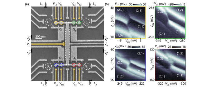
Figure 1a shows the two-dimensional layout of the quantum dot circuit, with the four qubits arranged in a x array (Q1, Q2, Q3 and Q4). Each qubit is encoded in a double quantum dot (DQD) and operated as a singlet-triplet spin qubit Petta2005 . Sensor quantum dots (S1-4) are placed on the outside of each DQD for single-shot qubit readout via spin-to-charge conversion Barthel2010 . For each sensor, this geometry gives good contrast between the charge states within its DQD, while four depletion gates with larger (rectangular) area help screening the electrostatic crosstalk from the other three DQDs.
The gate design also features an elongated gate at the center of the array, connected to circular regions under which the DQDs are formed. This gate is operated in accumulation mode, which not only improves dot confinements and gate control Martins2016 , but also accumulates a multielectron dot in the large elongated potential well (white dashed line). This central dot can be pulsed by control voltage (intended to mediate coherent spin-exchange between any two qubits) and can also serve as an inner electron reservoir for the DQDs. Fast voltage pulses can also be applied to gates labeled (false-colored in gold in Fig. 1a), allowing fast manipulation of all DQDs. All pulsed gate electrodes are wirebonded to bias-tees located on a high-bandwidth PCB sample holder where low-frequency tuning voltages and high-frequency control pulses are combined Qdevil . On the daughter board of the sample holder, four inductors with different inductances (=1200 nH, =560 nH, = 750 nH, = 910 nH) are capacitively coupled to one reflectometry channel of the cryostat, allowing frequency-multiplexed readout of all sensor dots Laird2010 .
Figure 1b shows charge stability diagrams for all DQDs, measured by digitizing the demodulated reflectometry signal of the proximal sensor dots Si (see below) as a function of the respective plunger gate voltages and . All devices are tuned to the (1,1) charge state with the (2,0)-(1,1) tunnel couplings adjusted to allow coherent operations as singlet-triplet qubits. (Numbers in parenthesis (,) represent the number of electrons on the left and right quantum dot, respectively.)
II.2 Simultaneous measurements
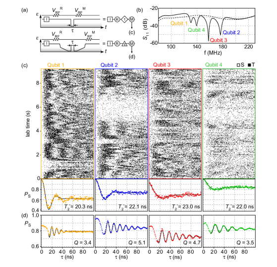
The distinct resonance frequencies associated with the inductors allow simultaneous measurements within the array, either by continuous excitation of all inductors (as was done in Fig. 1b), or by application of short readout bursts within each qubit operation cycle. Each qubit cycle involves a detuning pulse applied to all qubits, taking each DQD from (2,0) to (1,1) and back to (2,0) as illustrated in Fig. 2a as a decrease and increase of the detuning parameter . For each qubit, comparison of the demodulated reflectometry voltage during the measurement burst () with the demodulated voltage during the reference burst (, right after initialization of the DQD) allows assignment of single-shot readouts to each qubit, namely singlet if the measurement burst indicates a (2,0) charge state or triplet if the measurement burst indicates a (1,1) charge state.
Each reference and measurement burst applied to the cryostat comprises the four resonance frequencies, yielding qubit-resolved demodulated voltages due to the large separation of resonances in frequency domain (see Methods). Figure 2b shows the reflection coefficient of the sample holder Reilly2007 . Four well-separated resonances between MHz are clearly visible, which disappear one by one if gate voltages associated with the sensor dots are deactivated (dashed line) Laird2010 . (The overall low values are caused by intentional attenuation within the cryostat, which exceeds the gain of the cryogenic amplifier in the reflectometry channel.) During an experiment, the reflected bursts are amplified and then demodulated by four parallel homodyne mixers. The resulting four demodulated voltages are measured by a four-channel digitizer, and each channel analyzed to assign single-shot outcomes (Methods). The optimal burst duration depends on the qubit relaxation time and sensor signal-to-noise ratio. With a typical integration time of 10 s, we can distinguish (1,1) from (2,0) outcomes with a signal-to-noise ratio of approximately 5.
Figure 2c demonstrates simultaneous four-qubit single-shot readout after each qubit has precessed freely in the Overhauser gradient within its DQD. Each pixel, white for singlet outcome and black for triplet outcome, results from application of one 8-dimensional gate-voltage cycle that implements the top cycle in Fig. 2a for each qubit by pulsing and Malinowski2017 . After the qubit is initialized in its (2,0) singlet state (I), a detuning pulse quickly separates the two electrons by pulsing towards (1,1) where spin procession between and is driven by the Overhauser field gradient. After precession time , the DQD is pulsed back towards (2,0) to implement spin-to-charge conversion via Pauli blockade. Repeating this pulse cycle for different values of yields one row for all qubits. A plot of 512 rows obtained right after each other clearly shows four different Overhauser gradients fluctuating over a period of 9 seconds at four different locations of the same chip. While no obvious qubit-qubit correlations are visible in this data, an extension of the systematic study in Ref. Malinowski2017, to four qubits or an implementation of dynamical noise spectroscopy pulses that are specifically designed to measure spatio-temporal qubit-qubit correlations Luke2016 may provide useful insights for optimizing high-fidelity multi-qubit operations.
To estimate the inhomogeneous dephasing time for each qubit, we plot at the bottom of Fig. 2c the fraction of singlet outcomes, , for each value of . Fitting a semiclassical model of dephasing Petta2005 to the resulting decays yields times of approximately 20 ns, which is typical for singlet-triplet qubits in GaAs.
Figure 2d shows coherent exchange oscillations induced simultaneously in all qubits, by plotting for the lower pulse cycle in panel 2a. Here, an adiabatic detuning ramp from (2,0) to (1,1) prepares each qubit in the eigenstate of the Overhauser gradient before a quick detuning pulse of duration is applied that turns on an exchange interaction between the two spins. After the exchange pulse, an adiabatic ramp converts the resulting state into either singlet (2,0) or triplet (1,1) charge states. Coherent exchange oscillations in are clearly observed, with quality factors () similar to those observed for non-symmetric exchange pulses in single-qubit devices Martins2016 . The frequency of exchange oscillations can be tuned individually for each qubit by changing the amplitude of the detuning pulse, and has been chosen for Figure 2d to yield a rotation in 15 ns for all qubits.
II.3 Interleaved operations
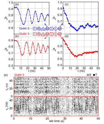
Insight into the finite visibility of exchange oscillations is obtained by alternating qubit exchange cycles and dephasing cycles, as shown in Fig. 3 for two of the qubits. In each alternation cycle, the first measurement bursts yields information about exchange rotations, whereas the second burst yields information about the prevailing Overhauser gradient. For convenience, the pulse duration for the exchange pulse is chosen the same as for the dephasing pulse (parameter in the symbolic qubit cycle in the inset of Fig. 3), and repeatedly stepped from 0 to 50 ns in 60 steps.
Plotting the fraction of singlet outcomes from the first measurement burst yields again conventional exchange oscillations for both qubits (Fig. 3a,b), whereas the second measurement burst yield dephasing data (Fig. 3c,d). However, if we inspect the underlying single-shot data, as done for Q3 in Fig. 3e, we observe a temporal correlation between periods of low visibility of exchange oscillations and low Overhauser gradients. We speculate that this indicates a failure of adiabatic conversions between (0,2) singlet states and (1,1) nuclear eigenstates ( or ) in periods of low Overhauser gradients, which could be mitigated by lowering the detuning ramp rate before and after the exchange pulse (cf. Fig. 2a). A similar visibility reduction for exchange oscillations can occur during periods of large Overhauser gradients, via a mechanism that reduces the triplet lifetime in the measurement configuration of the qubit’s DQD Barthel2012 .
More generally, knowledge of slowly fluctuating parameters in a multi-qubit processor, obtained from different types of interlaced diagnostic qubit operation cycles, may prove helpful for near-term applications of small and noisy quantum circuits.
II.4 Crosstalk between qubits
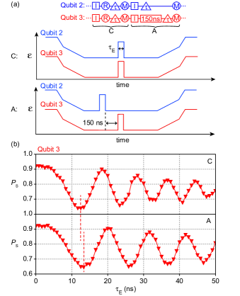
Fine tuning and optimization of simultaneous qubit operations may require to detect and account for capacitive crosstalk within qubit arrays. We test for qubit-qubit cross talk caused by simultaneous exchange pulses by modifying the interleaved operations of Fig. 3 such that the exchange coupling strength within one qubit (Q3) can be measured in the presence and absence of concurrent exchange pulses applied to its neighbor qubit (Q2). Figure 4a shows the specific waveforms used for the measurements in 4b, with interaction times =0…50 ns varied equally for both qubits in the presence and absence of a 150-ns asynchronization time.
We observe that the simultaneous exchange pulse applied to Q2 causes a small increase of the exchange coupling within Q3 (which is most obvious in Fig. 4b by comparing 6 rotations). This cross talk was taken into account (by tuning individual pulse parameters ) when demonstrating identical exchange speed for all qubits in Fig. 2.
II.5 Coupling to the central multielectron dot
So far we described single qubit operations. To investigate the possibility of two-qubit operations, we now show coherent spin exchange between qubit Q3 and the central multielectron dot (MED). Additional spin-exchange data for Q2 and Q3 is provided in the supplement.
Previous studies in linear arrays of quantum dots demonstrated coherent spin exchange between two singlet-triplet qubits across a MED Malinowski2018 . The discrete states of the MED played a central role in mediating the spin-spin coupling, but also gave rise to a variety of electron correlation and spin effects — including negative exchange couplings Martins2017 — if only one qubit is coupled with the MED. In that case, we generally expect that a temporary wavefunction overlap between a qubit spin and a MED with odd occupation results in spin dynamics that changes the state of the qubit spin, which can readily be detected as a suppression of if the qubit spin was initially part of a singlet pair within the DQD MalinowskiPRX2018 . (Unlike odd occupation, the ground state of an even occupied MED can be spinless, and Heisenberg spin exchange with a qubit spin may be absent.)
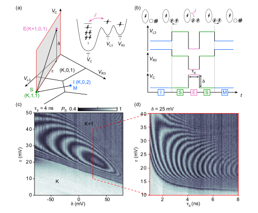
To search for coherent spin exchange with the MED, we therefore pulse one of the qubits (Q3) and the MED while keeping the other three DQDs in Coulomb blockade. This allows us to view the pulsed part of the device as a triple quantum dot controlled by , and with associated stability diagram as sketched in Fig. 5a. Here, the charge state of this triple dot is indicated by , where represents the charge state of the multielectron dot while and represent the charge state of the left and right well of the DQD.
After finding a suitable (but unknown) configuration of the multielectron dot (=K , see supplement), we demonstrate coherent exchange coupling with the mediator by repeating the following cycle and determining the fraction of singlet outcomes (refer to Fig. 5b): A singlet pair is prepared in the right well and isolated from the reservoirs by Coulomb blockade (I), by keeping the system within (K,0,2). The interwell charge transition is then traversed to separate the two entangled electrons from each other (S), by pulsing to (K,1,1) for the duration of one clock cycle of the waveform generator (0.83 ns). This operation effectively turns off the intra-DQD exchange interaction while preserving the initialized singlet. Then, an exchange pulse (E) of duration is applied to , and , with an amplitude parameterized by detuning and . Here, and , i.e. for sufficiently large and the triple dot transitions to another charge state, (K+1,0,1), thereby maximizing the wave function overlap between the left qubit spin and the spin of the multielectron dot (Fig. 5a, inset). (Here, are DC operating voltages associated with the three gate electrodes.) The qubit spin is returned to the left well, by pulsing to the separation point in (K,1,1) for one clock cycle, and read out by spin-to-charge conversion by pulsing towards (K,0,2). Any change of the qubit spin during the exchange pulse, coherent or incoherent, is expected to show up as a reduction of during the measurement burst (M).
A plot of for a fixed exchange pulse duration of 4 ns clearly shows a reduction above a critical pulse-amplitude threshold (sloped feature in Fig. 5c), which we associate with the charge transition between (K,1,1) and (K+1,0,1). Above that threshold, oscillates as a function of and , which we regard as evidence for coherent spin exchange processes from the MED MalinowskiPRX2018 .
The ring-like features in =constant) can be viewed as contours of constant exchange coupling strength, revealing a non-monotonic dependence of the exchange coupling on detuning and a prominent maximum. This is also evident if is varied for fixed (Fig. 5d). A qualitative comparison between this behaviour with a systematic study of a similar multielectron dot MalinowskiPRX2018 suggests that the MED occupation K is odd with an effective ground state spin of 1/2. In this interpretation, the emergence of a sweet spot and a sign reversal of the exchange coupling strength for larger detuning amplitudes arises from a competition of electron correlations on the multielectron dot and its relatively small level spacing Martins2017 .
III Discussion
In this work, using frequency-multiplexed high-frequency reflectometry sensors and 8-dimensional gate-voltage pulses, we demonstrate for the first time the simultaneous coherent manipulation and readout of four spin qubits.
Arranged in a 22 two-dimensional geometry and implemented as singlet-triplet qubits in GaAs, this allows us to sense temporal Overhauser fluctuations at four different sample locations. Our data does not show clear correlations between the four local GaAs nuclear environments. This supports the picture that statistical nuclear polarizations are local Taylor2007 and is consistent with nuclear spin diffusion occurring predominantly perpendicular to the plane of the 2DEG, into the heterostructure Petta2008 . However, we did not intentionally induce large nuclear polarizations, as previously done in single-qubit experiments Bluhm2010 . Our demonstration of spatio-temporal quantum sensing exemplifies the utility of qubit arrays beyond quantum computation, and can be refined in straightforward ways Luke2016 .
In addition to simultaneous exchange rotations within the array (with all qubits tuned to the same rotation speed), we also explored the diagnostic value of interleaving different qubit operations. Here, the alternation of Overhauser rotations and exchange rotations revealed potential errors in qubit initialization, providing additional insights for optimizing qubit fidelities that may supplement existing techniques, such as closed-loop control Cerfontaine2020self ; Cerfontaine2020 . A modification of interleaved operations then allowed us to detect a small change of exchange strengths in the presence of exchange pulses applied to other qubits, which we attribute to a small crosstalk from distant gate electrodes. We expect that automatic compensation of crosstalk will become even more important for controlling larger or denser qubit arrays at high fidelity.
Lastly, we demonstrated coherent spin exchange between one of the qubits and the central multielectron dot. The observed exchange profile is qualitatively in agreement with previous studies in linear arrays Martins2017 ; MalinowskiPRX2018 for an odd-occupied multielectron dot with an effective spin-1/2 ground state. However, additional data (supplement) suggests a prevalence of high-spin ground states that possibly arises from an enhancement of interaction effects by the large size of the multielectron dot, which in future experiments may affect the search for zero-spin ground states suitable for coherent two-qubit coupling Malinowski2018 .
Overall, our results suggest that large quantum dots may prove useful as tunable inter-qubit couplers to realize two-dimensional qubit networks. However, the large number of gate voltages that need to be tuned and synchronized is currently challenging for our manual tune-up procedures, and motivates the development of super-human automation Moon2020 .
IV Author contributions
S.F., G.C.G. and M.J.M. grew the heterostructure. F.F. fabricated the device. F.F., A.C., performed the experiments. F.F., A.C., F.K. analyzed data and prepared the manuscript.
V Acknowledgements
We thank Fabio Ansaloni for technical help and acknowledge support from the Innovation Fund Denmark and the Independent Research Fund Denmark. A.C. acknowledges support from the EPSRC Doctoral Prize Fellowship.
References
- (1) Watson, T. F., Weber, B., Hsueh, Y.-L., Hollenberg, L. C. L., Rahman, R. & Simmons, M. Y. “Atomically engineered electron spin lifetimes of 30 s in silicon”. Science Advances 3 (2017).
- (2) Muhonen, J. T. et al. “Storing quantum information for 30 seconds in a nanoelectronic device”. Nature Nanotechnology 9, 986–991 (2014).
- (3) Yoneda, J. et al. “A quantum-dot spin qubit with coherence limited by charge noise and fidelity higher than 99.9%”. Nature nanotechnology 13, 102–106 (2018).
- (4) He, Y., Gorman, S. K., Keith, D., Kranz, L., Keizer, J. G. & Simmons, M. Y. “A two-qubit gate between phosphorus donor electrons in silicon”. Nature 571, 371–375 (2019).
- (5) Watson, T. F. et al. “A programmable two-qubit quantum processor in silicon”. Nature 555, 633–637 (2018).
- (6) Zajac, D. M., Sigillito, A. J., Russ, M., Borjans, F., Taylor, J. M., Burkard, G. & Petta, J. R. “Resonantly driven cnot gate for electron spins”. Science 359, 439–442 (2018).
- (7) Veldhorst, M. et al. “A two-qubit logic gate in silicon”. Nature 526, 410–414 (2015).
- (8) Chatterjee, A., Stevenson, P., De Franceschi, S., Morello, A., de Leon, N. P. & Kuemmeth, F. “Semiconductor qubits in practice”. Nature Reviews Physics 3, 157–177 (2021).
- (9) Zajac, D. M., Hazard, T. M., Mi, X., Nielsen, E. & Petta, J. R. “Scalable gate architecture for a one-dimensional array of semiconductor spin qubits”. Phys. Rev. Applied 6, 054013 (2016).
- (10) Mortemousque, P.-A., Chanrion, E., Jadot, B., Flentje, H., Ludwig, A., Wieck, A. D., Urdampilleta, M., Bäuerle, C. & Meunier, T. “Coherent control of individual electron spins in a two-dimensional quantum dot array”. Nature Nanotechnology 16, 296–301 (2021).
- (11) Kojima, Y. et al. “Probabilistic teleportation of a quantum dot spin qubit”. arXiv preprint arXiv:2011.04881 (2020).
- (12) Ito, T. et al. “Four single-spin rabi oscillations in a quadruple quantum dot”. Applied Physics Letters 113, 093102 (2018).
- (13) Qiao, H., Kandel, Y. P., Deng, K., Fallahi, S., Gardner, G. C., Manfra, M. J., Barnes, E. & Nichol, J. M. “Coherent multispin exchange coupling in a quantum-dot spin chain”. Phys. Rev. X 10, 031006 (2020).
- (14) Sigillito, A., Loy, J., Zajac, D., Gullans, M., Edge, L. & Petta, J. “Site-selective quantum control in an isotopically enriched quadruple quantum dot”. Phys. Rev. Applied 11, 061006 (2019).
- (15) Takeda, K., Noiri, A., Nakajima, T., Yoneda, J., Kobayashi, T. & Tarucha, S. “Quantum tomography of an entangled three-spin state in silicon”. arXiv preprint arXiv:2010.10316 (2020).
- (16) Hendrickx, N. W., Lawrie, W. I., Russ, M., van Riggelen, F., de Snoo, S. L., Schouten, R. N., Sammak, A., Scappucci, G. & Veldhorst, M. “A four-qubit germanium quantum processor”. Nature 591, 580–585 (2021).
- (17) Hensgens, T., Fujita, T., Janssen, L., Li, X., Van Diepen, C., Reichl, C., Wegscheider, W., Sarma, S. D. & Vandersypen, L. M. “Quantum simulation of a fermi–hubbard model using a semiconductor quantum dot array”. Nature 548, 70–73 (2017).
- (18) Malinowski, F. K. et al. “Fast spin exchange across a multielectron mediator”. Nature Communications 10, 1196 (2019).
- (19) Dehollain, J. P., Mukhopadhyay, U., Michal, V. P., Wang, Y., Wunsch, B., Reichl, C., Wegscheider, W., Rudner, M. S., Demler, E. & Vandersypen, L. M. “Nagaoka ferromagnetism observed in a quantum dot plaquette”. Nature 579, 528–533 (2020).
- (20) Petta, J., Johnson, A., Taylor, J., Laird, E., Yacoby, A., Lukin, M., Marcus, C., Hanson, M. & Gossard, A. “Coherent Manipulation of Coupled Electron Spins in Semiconductor Quantum Dots”. Science 309, 2180–2184 (2005).
- (21) Barthel, C., Kjaergaard, M., Medford, J., Stopa, M., Marcus, C. M., Hanson, M. P. & Gossard, A. C. “Fast sensing of double-dot charge arrangement and spin state with a radio-frequency sensor quantum dot”. Physical Review B 81, 161308(R) (2010).
- (22) Martins, F., Malinowski, F. K., Nissen, P. D., Barnes, E., Fallahi, S., Gardner, G. C., Manfra, M. J., Marcus, C. M. & Kuemmeth, F. “Noise suppression using symmetric exchange gates in spin qubits”. Phys. Rev. Lett. 116, 116801 (2016).
- (23) Available from https://www.qdevil.com.
- (24) Laird, E. A., Taylor, J. M., DiVincenzo, D. P., Marcus, C. M., Hanson, M. P. & Gossard, A. C. “Coherent spin manipulation in an exchange-only qubit”. Phys. Rev. B 82, 075403 (2010).
- (25) Reilly, D., Marcus, C., Hanson, M. & Gossard, A. “Fast single-charge sensing with a rf quantum point contact”. Applied Physics Letters 91, 162101 (2007).
- (26) Malinowski, F. K., Martins, F., Cywiński, L., Rudner, M. S., Nissen, P. D., Fallahi, S., Gardner, G. C., Manfra, M. J., Marcus, C. M. & Kuemmeth, F. “Spectrum of the nuclear environment for gaas spin qubits”. Phys. Rev. Lett. 118, 177702 (2017).
- (27) Szańkowski, P., Trippenbach, M. & Cywiński, L. “Spectroscopy of cross correlations of environmental noises with two qubits”. Phys. Rev. A 94, 012109 (2016).
- (28) Barthel, C., Medford, J., Bluhm, H., Yacoby, A., Marcus, C. M., Hanson, M. P. & Gossard, A. C. “Relaxation and readout visibility of a singlet-triplet qubit in an overhauser field gradient”. Phys. Rev. B 85, 035306 (2012).
- (29) Martins, F., Malinowski, F. K., Nissen, P. D., Fallahi, S., Gardner, G. C., Manfra, M. J., Marcus, C. M. & Kuemmeth, F. “Negative spin exchange in a multielectron quantum dot”. Phys. Rev. Lett. 119, 227701 (2017).
- (30) Malinowski, F. K. et al. “Spin of a multielectron quantum dot and its interaction with a neighboring electron”. Phys. Rev. X 8, 011045 (2018).
- (31) Taylor, J., Petta, J. R., Johnson, A. C., Yacoby, A., Marcus, C. M. & Lukin, M. D. “Relaxation, dephasing, and quantum control of electron spins in double quantum dots”. Physical Review B 76, 035315 (2007).
- (32) Petta, J. R., Taylor, J. M., Johnson, A. C., Yacoby, A., Lukin, M. D., Marcus, C. M., Hanson, M. P. & Gossard, A. C. “Dynamic nuclear polarization with single electron spins”. Phys. Rev. Lett. 100, 067601 (2008).
- (33) Bluhm, H., Foletti, S., Mahalu, D., Umansky, V. & Yacoby, A. “Enhancing the coherence of a spin qubit by operating it as a feedback loop that controls its nuclear spin bath”. Phys. Rev. Lett. 105, 216803 (2010).
- (34) Cerfontaine, P., Otten, R. & Bluhm, H. “Self-consistent calibration of quantum-gate sets”. Physical Review Applied 13, 044071 (2020).
- (35) Cerfontaine, P., Botzem, T., Ritzmann, J., Humpohl, S. S., Ludwig, A., Schuh, D., Bougeard, D., Wieck, A. D. & Bluhm, H. “Closed-loop control of a gaas-based singlet-triplet spin qubit with 99.5% gate fidelity and low leakage”. Nature communications 11, 1–6 (2020).
- (36) Moon, T. “Machine learning enables completely automatic tuning of a quantum device faster than human experts”. Nature Communications 11, 4161 (2020).
- (37) Medford, J., Beil, J., Taylor, J., Rashba, E., Lu, H., Gossard, A. & Marcus, C. M. “Quantum-dot-based resonant exchange qubit”. Physical review letters 111, 050501 (2013).
VI Methods
VI.1 Material and device fabrication
The device was fabricated on a GaAs/AlGaAs heterostructure with a 2DEG 57 nm below the surface with carrier density x m-2 and mobility mVs . The qubit array was realised using standard electron-beam lithography to pattern Ti/Au metallic gates, after the deposition of a 10-nm thick layer of HfO2. This insulating layer allows the application of both positive and negative gate voltages and obviates the need of bias cooling Martins2016 . For Figures 1-4 the accumulation gate was held at +50 mV, while it was set to +75 mV for Figure 5.
VI.2 Synchronization of 8-dimensional voltage pulses
The four qubits are simultaneously controlled by application of 8-dimensional gate-voltage pulses. This required sub-nanosecond synchronization of two four-channel arbitrary waveform generators (Tektronix 5014C), which we achieved by triggering both generators with voltage pulses applied via identical cables. In addition, each instrument was synchronized to a 10-MHz frequency standard (SRS FS725).
VI.3 Four-qubit single-shot readout
To acquire and analyze the demodulated voltage of all four sensor quantum dots during each waveform cycle, we extended previous approaches for frequency multiplexing Laird2010 (see supplementary Figure S1 for details) and state identification Malinowski2018 . Specifically, during each operation cycle, the four reflectometry tones are temporarily switched on before and after the separation pulse. This allows the acquisition of one reference measurement () after the singlet initialization, and one actual measurement () after the qubit operation. To assign single-shot outcomes, the demodulated voltage of each reference burst is subtracted from the demodulated voltage of the measurement burst. The outcomes are then collected into a histogram and fitted with a double Gaussian function. The midpoint between the two Gaussians serves as a voltage threshold, i.e. we assign all outcomes on the singlet (triplet) side to 1 (0). This identification of qubit states is similar to single-qubit readout in earlier experiments Barthel2010 , with the additional improvement that the subtraction prior to histogramming makes our method insensitive to small and slow drifts of the sensor operating points, allowing the execution of many qubit cycles over long periods of time.
Similar to previous work Laird2010 , we find that the depths of the readout resonances in Figure 2b depend on the tuning (predominantly conductance) of the sensor dots. To improve single-shot readout of the experiments reported in this work, each sensor tuning had been optimized relative to the configuration of Figure 2b.
Appendix A Supplementary Information for ”Simultaneous operations in a two-dimensional array of singlet-triplet qubits”
A.1 Demodulation of four carrier frequencies
To perform simultaneous qubit readout we extended to four channels a frequency multiplexing setup similar to that in Ref. Laird2010, . Our setup is shown in Figure S1 as a circuit schematic and as a photograph of the demodulation circuit.
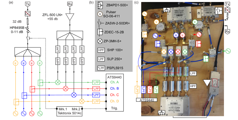
Four carrier frequencies are generated using independent RF sources (SRS386). Each frequency is passed through a directional coupler that separates the probe tone from the reference tone. Each probe tone is then passed through a voltage controlled phased shifter, before being added with the other probe tones using a four-port power splitter. The resulting signal now contains all four carrier frequencies and is passed through an high-frequency switch, followed by a series of attenuators and filters before being injected into the transmission port (Tx) of the cryostat. Inside the cryostat (not shown), the four carriers are further attenuated before reaching a directional coupler that applies a fraction of the signal to four LC resonators located on the PCB sample holder Qdevil . Each resonator is wirebonded to an ohmic contact of one of the four sensor quantum dots. Since each resonator is excited only by one of the carrier frequencies (whichever one is resonant with the LC circuit), this provides qubit addressability.
After being reflected by the sample the four carriers are directed by the directional coupler to a cryogenic amplifier before exiting the cryostat at its receiver port (Rx). The signal is then further amplified at room temperature before being split into four equal components by a four-port power splitter. Finally, each component is mixed with one of the reference tones. The demodulated output of each mixer is then low-pass filtered and recorded by a fast digitizer card (Alazar ATS9440).
To implement the reference and measurement bursts described in the method section of the main text, we drive the high-frequency switch located before the Tx port with a marker channel of the arbitrary waveform generator (dashed black line in Figure S1a). A second marker is connected to the trigger port of the Alazar card to mark the beginning of a acquisition. To account for an inevitable delay between the triggers and the instant the signal is received from the demodulation circuit, caused by propagation delays associated with cables and cryostat wiring, we adjust the post-trigger delay of the Alazar card such that its sampling starts after the trigger is received (in our case 500 ns).
A.2 Additional data for spin exchange with the multielectron dot
In Figure S2a we show the demodulated voltage measured from S3 (after the subtraction of a background plane) as a function of and . The resulting charge stability diagram shows horizontal and vertical transitions associated with charging events of the left dot of qubit 3 and the multielectron dot, respectively. White dashed lines highlight inter-dot charge transitions that can be traversed (along suitable detuning directions ) to test for coherent coupling with the multielectron dot. These data were taken column by column, to allow the multielectron dot sufficient time to exchange electrons with one of the reservoirs while is slowly changed, likely via leakage through the Q1 or Q4 double dot.
In Figure S2b we use the same exchange sequence used for Figure 5 and measure the demodulated voltage of S3 as a function of the detuning parameter and the MED plunger gate . As function of the number of electrons in the MED changes by one approximately every 40-50 mV. Within one charge state, an increase in has the same effect as an increase of in Figure 5d. We can clearly observe coherent exchange oscillations in several consecutive charge occupations. Since coherent oscillations indicate the presence of an unpaired spin in the MED, this behavior is inconsistent with a single-particle picture of the multielectron dot in which the ground-state spin alternates between S=0 and S=1/2. Deviations from this simple non-interacting picture have previously been observed by Malinowski et al. using a single-triplet qubit coupled to a multielectron dot MalinowskiPRX2018 . We speculate that the ground state of the MED alternates between S=1/2 and S=1 in this region.
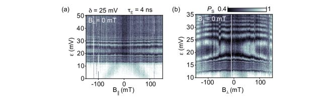
The presence of non-zero spin configurations in all three consecutive occupations is further confirmed by leakage spectroscopy measurements, see Figure S2c. Leakage spectroscopy data are obtained by pulsing qubit 3 and the MED with the same waveforms used in the main text (see Fig. 5b) but with longer interaction time (fixed at =150 ns, sufficiently long to detect incoherent spin mixing between the MED and the qubit electron). Markers indicate the choice of for each measurement, whereas the triangle indicates the value of for the data presented in Fig. 5c-d.
As a function of detuning and in-plane magnetic field B∥, we observe in all three cases a U-like leakage feature. Similar features arise in three-electron triple dots (in Ref. medford2013, the feature arises from the crossing of two states with different spin projections, denoted as with ) and have also been observed by coupling a singlet-triplet qubit to a spin-1/2 and spin-1 multielectron dot Martins2017 ; MalinowskiPRX2018 .
Figure S3 shows the effect of applied magnetic field on the exchange profile of Figure 5d. Regarding contours of equal as points of constant exchange coupling strength, we observe that in-plane (B∥) and out-of-plane (B⟂) magnetic fields have no strong effect on the exchange strength. The weak dependence on B∥ is consistent with similar observations by Martins et. al. for a linear array with somewhat smaller multielectron dot, although they found a stronger dependence on B⟂ that was vaguely attributed to orbital magnetic effects Martins2017 .
Orbital effects can potentially be studied by changing the size or shape of the multielectron dot by tuning the four large depletion gates (”backbone gates”) that are surrounding the elliptical area indicated in Figure 1a. We have not systematically studied this capability, but note that for experiments in Fig. S2,S3,S4 and 5 the depletion voltages applied to the upper two backbone gates (-0.70 V for Q1 and Q4) were more negative relative to the lower two backbone gates (-0.54 V and -0.56 V for Q2 and Q3). In this regime, we do not have direct experimental evidence that the multielectron dot extends all the way underneath the ellipse indicated in Figure 1a. (In the regime where tunnel barriers associated with upper and lower qubits are low, and where upper backbone voltages are comparable to lower backbone voltages, we did verify Coulomb blockade of the fully-extended quantum dot by measuring transport between ohmics located on the upper and lower sides of the chip.)
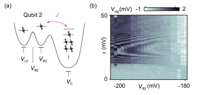
The pulse sequence described in Figure 5 can also be applied to other qubits. For example, by pulsing and instead of and we can view the pulsed part of the device as a triple quantum dot comprised of Q2 and the multielectron dot (Fig. S4a), while Q3 remains in Coulomb blockade. The resulting coherent exchange oscillations from Q2 (detected by measuring ) are presented as columns in Figure S4b, for different voltages applied to the DQD barrier gate (). The dependence of exchange oscillations on suggests that the effective detuning of the multielectron dot and the resulting exchange coupling strength are affected somewhat by capacitive cross coupling from the barrier gate. During this experiment, all other tuning voltages are identical to those used for the Q3 spin-exchange experiments (corresponding to the triangular marker in Figure S2b), indicating that multi-qubit coupling to the multielectron dot is possible. However, we have not yet demonstrated qubit-qubit coupling mediated by the multielectron dot (ideally the coupling of any qubit to any other qubit), but expect that more efficient tuning techniques (for example based on automation) will allow this in future.
A.3 T fits and exchange quality factors
Fits for the time averaged data of Figure 2c in the main text are adapted from Ref. Petta2005, using an exponentially damped sine function:
| (1) |
with , and as free parameters. Here, quantifies the inhomogenous dephasing time due to hyperfine interactions with nuclear spins.
The fits for the exchange oscillations in Figure 2d are obtained using the function:
| (2) |
with , and as free parameters. Here, is sensitive to decoherence arising from noise in the exchange coupling strength , and likely has contributions from effective electrical noise. Quality factors are obtained by following Ref. Martins2016, . Previous work in Ref. Malinowski2018, has shown that the high-frequency wiring of the cryostat results in a finite rise time of exchange pulses, which results in deviations from Eq. 2 for short values of . In Figure 2d, we therefore exclude data of the first 15 ns from the fits.