Fisheye-Lens-Camera-based Autonomous Valet Parking System
Abstract
This paper proposes an efficient autonomous valet parking system utilizing only cameras which are the most widely used sensor. To capture more information instantaneously and respond rapidly to changes in the surrounding environment, fisheye cameras—which have a wider angle of view compared to pinhole cameras—are used. Accordingly, visual simultaneous localization and mapping (SLAM) is used to identify the layout of the parking lot and track the location of the vehicle. In addition, the input image frames are converted into around-viewmonitor (AVM) images to resolve the distortion of fisheye lens because the algorithm to detect edges are supposed to be applied to images taken with pinhole cameras. The proposed system adopts a look-up table for real-time operation by minimizing the computational complexity encountered when processing AVM images. The detection rate of each process and the success rate of autonomous parking were measured to evaluate performance. The experimental results confirm that autonomous parking can be achieved using only visual sensors.
Index Terms:
Autonomous Valet Parking System, AVM, Fisheye Lens, Look Up Table, SLAM, Template MatchingI INTRODUCTION
AS self-driving technology continues to develop with the aim of absolutely unaided driving, advanced driverassistance systems (ADAS) are likewise developing with the goal of complete automation, which is the fifth level of automation defined by the Society of Automotive Engineers(SAE).
Typical ADAS technology includes an autonomous parking system that aids drivers in precise and facile parking. Developed and presented jointly by German automotive multinationals Daimler AG and Robert Bosch, the autonomous valet parking (AVP) system allows the vehicle to be parked and recalled through a dedicated smartphone application. In the case of Hyundai’s and Kia’s automatic parking support systems, the speed and transmission are operated by the vehicle itself via ultrasonic sensors attached to the vehicle.
However, there are still many problems with existing autonomous parking systems. For instance, AVP systems (Daimler AG and Bosch) provide parking-space information to self-parking vehicles by installing sensors in the parking lot itself; these sensors are expensive to install and difficult to commercialize because the core of the system is in the parking lot itself. In addition, in AVP, the driver must first move the car directly into the parking lot and near the preferred parking bay, providing only simple functions such as basic reversing. On the other hand, self-parking systems using ultrasonic sensors are limited in that parking is impossible when the lot is empty; these systems cannot obtain information about the vehicle’s vicinity when there is no parked vehicle for reference.
Therefore, in this study, we propose a automated AVP system utilizing efficient path-generation and driving strategies in parking lots where lane and signal information are unclear. Essentially, the system improves general functionality at a lower cost. For instance, should the driver disembark at any location and run the proposed system, the car will navigate into the parking lot independently; if an empty bay is located, the car will park unaided. The novel system uses neither light detection and ranging (LiDAR) sensors that otherwise hinder commercialization due to expensive unit prices [1], nor GPS sensors that cannot obtain information inside the parking lot except location information [2], nor ultrasonic sensors that only measure the distance from nearby objects, and are hence less accurate. Instead, similar to the method proposed in [3], this system performs autonomous parking using a fisheye camera and a sensor that accurately identifies information in the indoor parking lot while having an affordable unit price.
II PROPOSED DESIGN
II-A Overall System Architecture
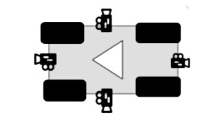
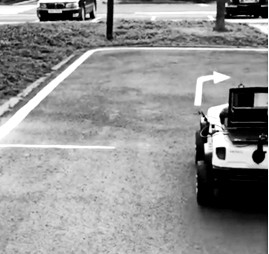
Four camera sensors are attached in four directions (front, rear, left, and right) as in Fig. 1. Visual simultaneous localization and mapping (SLAM) is run using footage captured by the front camera to map the layout of the parking lot and simultaneously pin-point the current location of the vehicle. The front camera is also used to detect signs such as direction indicator arrows. The other sensors are used to detect empty parking bays and to accordingly execute the parking algorithm.
Monocular pinhole lenses have an angle of view narrower than 50°, making it difficult to obtain information about the vicinity, such as parking lines and obstacles on the pavement. In this regard, the proposed system uses fisheye lenses with an angle of view of 180° to capture more information through the cameras.
While fisheye lenses have the advantage of having a wide angle of view, they have the disadvantage of distortion in images as illustrated in Fig. 2 In other words, visual SLAMs based on ordinary lenses, such as ORB SLAM [4], cannot be used. Consequently, the process of correcting the distortion of fisheye-lens images is necessary to utilize the information captured. To this end, location estimation and mapping are performed using CubemapSLAM [5] to resolve distortions. CubemapSLAM is based on a previous study, which asserts that feature extraction and pattern recognition are possible in images captured via a fisheye lens [6]. Moreover, Cubemap- SLAM uses ORB feature, which is more efficient compared to SIFT and SURF [7]. As depicted in Fig. 3, the image is projected onto the cube to correct the distortion, and features are extracted from the unfolded cube image.
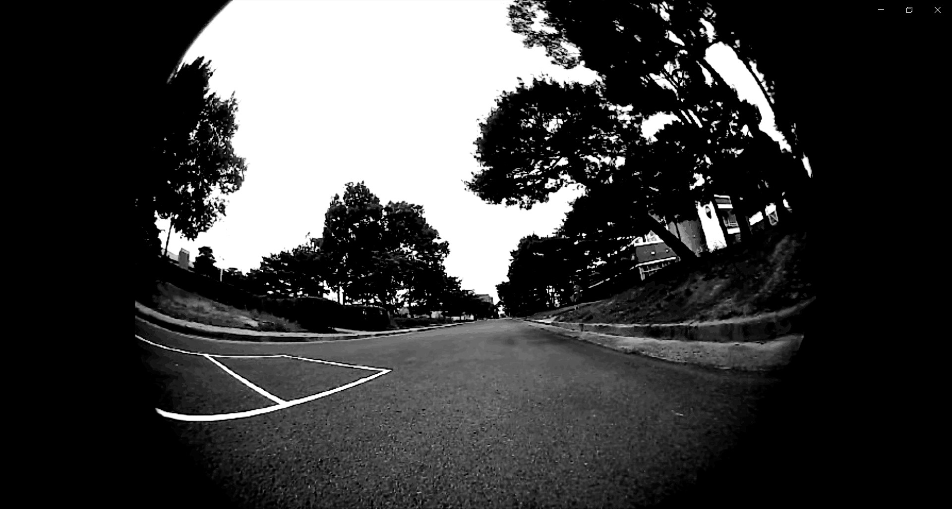
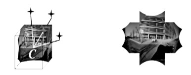
Fig. 4 is a brief flow chart of the system, which is largely divided into four parts: initial self-driving before loop closing, keyframe-based self-driving after loop closing, autonomous parking, and return to the spot where the driver calls from.
The first step (self-driving before loop closing) involves analyzing the images through the camera sensors. When the driving image frame is input into the system, the system starts the initial autonomous driving. Straight driving is the default setting for the initial driving, and the vehicle is steered by identifying road markings in the parking lot while driving. In this phase, the vehicle also constructs the SLAM map by going around the parking lot.
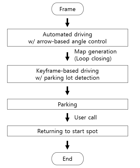
If the vehicle arrives at the start position, the vehicle does not repeat the identification phase; instead, it drives along the keyframe in the SLAM map. Each keyframe has its own unique identification number in the order in which it is generated, and sorting based on this number allows it to be accessed sequentially. Loop closing is one of the SLAM processes that corrects cumulative errors by evaluating that a loop is created upon revisiting an area of the parking lot; loop closing facilitates precise three-dimensional (3D) mapping with minimal space error. This implies that the route traversed by the vehicle also becomes more accurately defined. Thus, it is possible to drive unaided in the order in which the keyframes were generated.
If a vacant parking bay is found, the vehicle is driven to the appropriate location and the parking algorithm is executed. The location that the vehicle shall be moved to is indicated in the SLAM map; the real-time location of the vehicle is consistently tracked by checking whether it is moving appropriately.
II-B Detailed Design
1) Autonomous Driving before Loop Closing
Owing to lack of information on the layout of the parking lot prior to loop closing, the driving direction and steering of the vehicle should be determined by information found in the parking lot. We developed the system under the assumption that the parking lot has markings (arrows) on the floor that indicate the direction in which the vehicle should proceed.
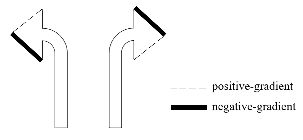
The head and tail of the arrow are detected to identify the direction that the arrow indicates[8]. The arrows used in this study were left and right arrows; the gradient of the two edges of the arrow head is detected and the center of each edge is compared to increase the accuracy of the arrow identification. For example, the left arrow is identified if the center of the edge with a positive gradient is above the center of the edge with a negative gradient as shown in Fig. 5, and vice versa. To prevent erroneous identification cases due to noise, the rotation control command was applied when more than 10 frames were continuously identified in the same direction. Moreover, arrow identification is not performed while the vehicle is rotating to allow the vehicle to smoothly rotate by 90°.
2) Autonomous Driving after Loop Closing
After loop closing occurs, the keyframes are sorted in the order in which they were generated, and the keyframes currently in front of the vehicle are followed as the vehicle retraces its route. The vehicle’s coordinate system is used to locate the target keyframe; this keyframe determines the direction followed by the vehicle as well as steering angles.
To ensure that the vehicle reaches the target keyframe, it is necessary to check the distance between the vehicle and the target keyframe. The arrival criteria are set as the average of the distances between adjacent keyframes. Nonetheless, if the target keyframe is located behind the vehicle, it is assumed that the vehicle has already passed that keyframe.
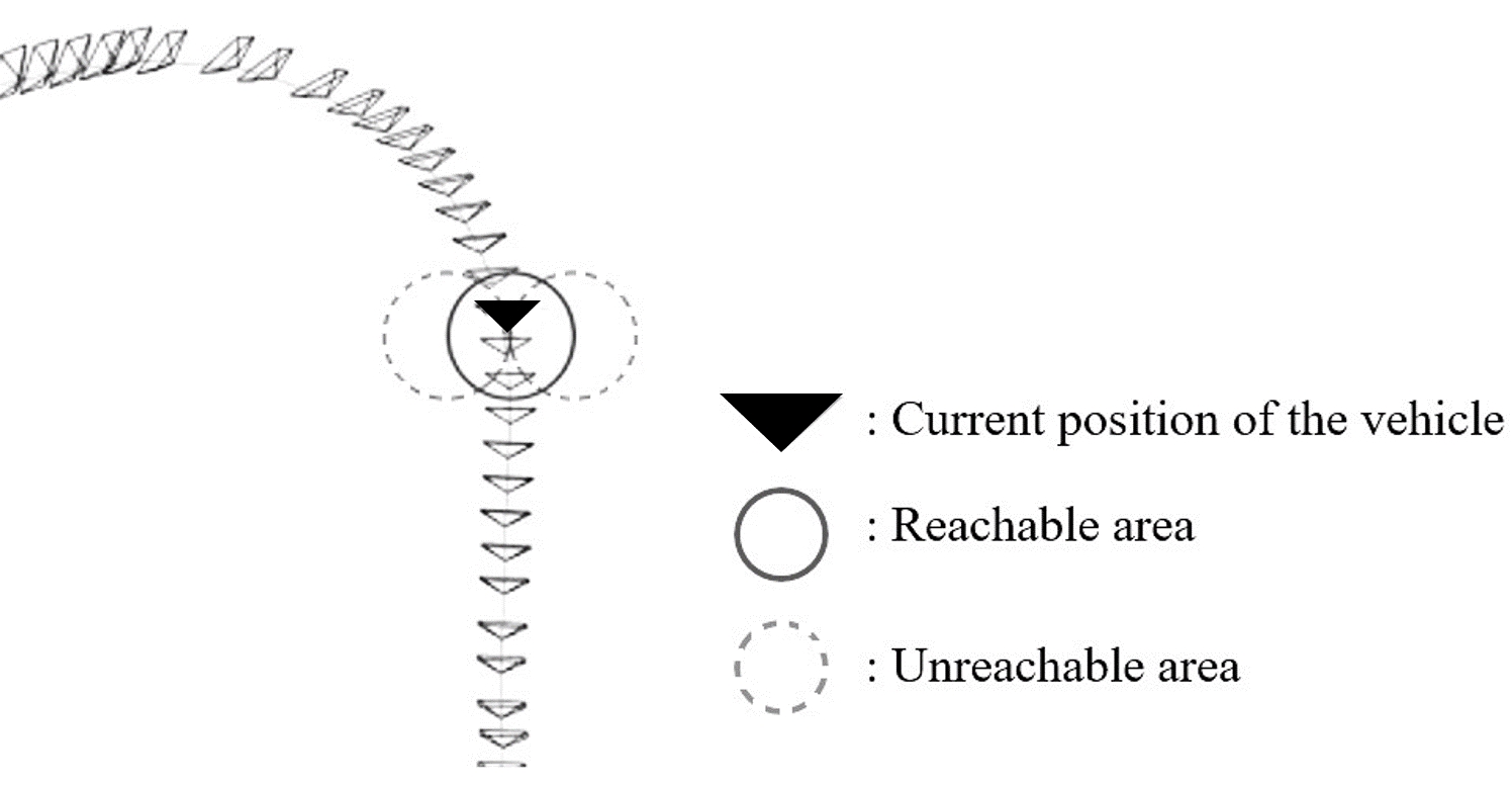
Exception handling is required when the vehicle cannot autonomously reach the target keyframe position. The values of y-axis representing height on the 3D map have no significant effect on determining direction. Therefore, the position of all keyframes is projected onto the xz-plane. The equation of a circle passing through all three adjacent coordinates (x1, z1), (x2, z2), and (x3, z3) of the projected position is obtained using equation 1 and 2.
The minimum value of the radius obtained using equation 1 is set as the turning radius of the vehicle, as well as the radius of the unreachable area as shown in Fig. 6.
If the subsequent keyframe is located in the unreachable area, the vehicle applies corrective maneuvers. For example, if the keyframe is located on the left side, the vehicle reverses to the right until the keyframe is out of the unreachable area, and vice versa.
3) Empty Parking Space Identification
In general, parking lines are detected to identify empty parking spaces in the video, and parking spaces are identified using the angle of parking lines, the separation between lines, location of lines, and so on. Such parameters generally limit accurate detection of parking spaces to particular environments. The proposed system reinforces existing linedetection methods and proposes an adaptive parking-space detection method using template matching techniques [12]. These methods can detect parking spaces of various shapes without numerical constraints and reduce cases of erroneous detection.
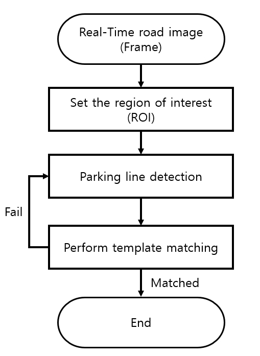
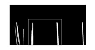
Fig. 7 shows the sequence of empty-parking-space detection algorithms. When loop closing occurs while driving, the camera receives images from the front, rear, left, and right of the vehicle as system input. Given that parking lot images typically contain a large number of lines, detecting lines for all pixels in the image reduces the accuracy of detection and also puts a strain on the system in terms of computational speed. To solve this problem, the proposed system has a preliminary process that uses only a subset of the images by designating a region of interest (ROI). Thereafter, the relevant parking line and the corresponding parking bay are detected in the area of interest. The detected line segment is used as the target image in the template-matching technique. A software that finds similarities between the target image and the template is then utilized to identify the parking space. If the two images are deemed similar, the corresponding area is positively identified as a parking space and the parking algorithm is executed. However, in case of failure, the driving continues and the other parking spaces are explored.
To detect parking spaces, parking lines demarcating parking spaces must first be detected. OpenCV supports several linesegment detection algorithms. Nevertheless, conventional linesegment detection algorithms such as Houghline [9, 10] are adversely affected by environmental changes—each change in image environment necessitates modification of the value provided as a function factor. In addition, because such an algorithm detects one long line with several short/broken lines as well as non-parking lines, it is detrimental to use only conventional line-segment detection methods. Therefore, for more accurate and adaptive line detection in this system, the line-filtering technique [11] was used to detect the edges; the detected edges were in turn used to detect corresponding parking lines.
Line filtering software makes parking lines brighter than their surroundings. Upon applying the horizontal and vertical line filters (equation 3 and 4, respectively) to one point in the image, the calculated values are used to obtain a specific point brighter than the surrounding area. L(x; y) in the linefilter equations denotes the intensity (brightness) value at the coordinates (x, y).
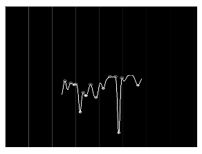
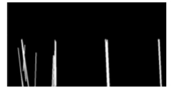
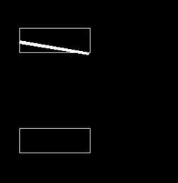
The graph in Fig. 8 is the result of applying a horizontal line filter for any y-value. Given the large difference between adjacent pixels and brightness values, the boundaries of the parking line display a large height difference on the graph. The median values of peak and valley above the threshold are used as definite points as shown in Fig. 9. In this manner, the line filter is applied to all pixels in the ROI to obtain the specific points, and these points are used as edges to detect the parking lines. A parking space typically consists of two split lines and one base line, but sometimes only two split lines. In this system, additional base lines in the parking space were detected using the identified split lines. The split lines were also used to detect parking spaces regardless of the baseline.
The template-matching technique was used to determine whether the area of the detected line composes the parking space. Template matching is a technology that determines if there is an area that matches the template image in the target image. In order to perform template matching, a parkingspace database must first be established. In this system, parking-space images of various shapes were compiled into a template database and easily compared to target images. After template matching, the vehicle positioning and parking steps were carried out. Fig. 13 shows the result of template matching.

4) Look-Up Table (LUT)
Because the camera attached to the vehicle was a fisheye camera, it was impossible to apply algorithms to detect edges and lines in images of parking lots due to severe image distortion. Therefore, to identify the parking space, we corrected the distortion of the image acquired from the four-way camera and merged it into the aerial AVM image. However, the slow processing speed of the merging process is not suitable for the real-time parking system.
To solve this problem, the proposed system employed a look-up table (LUT) containing mapping relationships between AVM images and fisheye-camera images. After storing the ROI of the AVM image that needs to be calculated in advance to the LUT, the system performed parking-line detection by approaching the pixel value corresponding to the coordinates of the fisheye image in the LUT. Realtime performance is guaranteed by significantly reducing processing time owing to the manner in which information is stored in the LUT and read only when necessary.
5) Parking
Parking is implemented in five steps. The first step is to locate the vacant parking space after positively identifying it through the aforementioned process. In this step, the steering angle of the wheels is changed in the opposite direction of the parking bay. The vehicle is then driven forward a certain distance—approximately 1.8 m depending on the type of vehicle. To keep within 1.8 m, the vehicle is driven while comparing the current location of the vehicle with the destination indicated after mapping (the destination was mapped 1.8 m away in the SLAM map). The scale between SLAM maps and topographical maps is required for proper mapping. To address this, the system began computing the scale at the start of the drive.
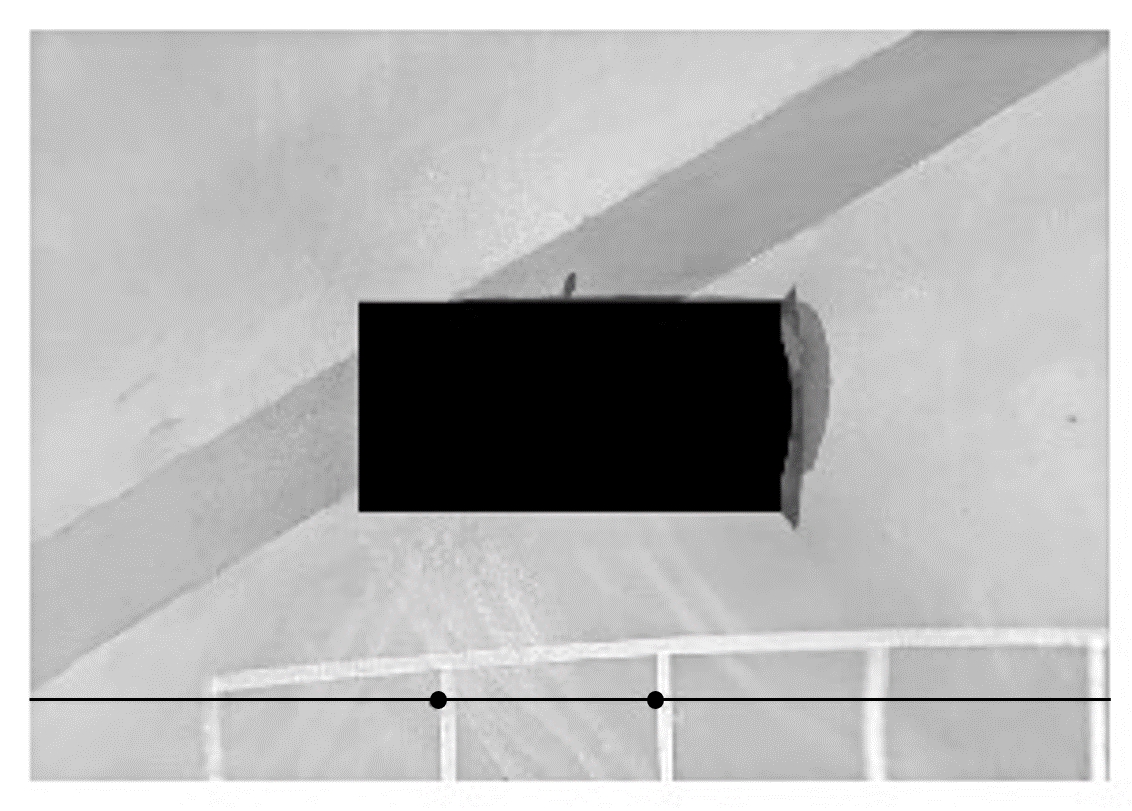
One line was placed on the left side of the starting position as shown in Fig. 14. This line on the left is called the scale line. As the vehicle moves forward at a constant speed, the scale line is detected by the parking-line detection algorithm.
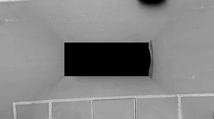
Scale lines are detected in aerial images as shown in Fig. 15. When the scale line crosses two pre-specified areas in the aerial image, the SLAM map displays the coordinates of the vehicle at these points. When the vehicle is past the scale line, the SLAM map shows coordinates of two vehicles. The scale ratio between the aerial image and the SLAM map is calculated using the length difference between this pair of coordinates and the distance between a pre-specified area in the aerial image.
This information is saved and driving continues. If a parking lot is detected while driving, the aerial image will show the parking line as described earlier. Comparing the length of the parking line shown in the aerial image with the length of the actual parking line, the scale between the topographical and aerial images is also calculated.
The scale between the SLAM map and the aerial image and that between the aerial image and the topographical map ultimately allows for the derivation of the scale between the SLAM map and the topographical map. This scale allows the SLAM map to display the previously determined destination approximately 1.8 m away. After the vehicle moves to a destination that is a certain distance away, the third step of parking is carried out. In the third step, the vehicle’s wheels are turned in the direction of the parking bay and the vehicle is then reversed. If the vehicle is parallel to the parking line while reversing, the steering angle of the vehicle is restored so that the vehicle’s wheels are flush with the body of the vehicle (i.e., parallel to the parking line as well). The fisheye cameras attached to the left and right of the vehicle are used for determining whether the vehicle is parallel to the parking line. The slope of the detected lines is obtained in advance when the vehicle is parallel to the parking line. The slope of the lines in the left/right camera image is then compared with the slope obtained in advance while reversing. If the two slopes are identical, the vehicle is considered to be parallel to the parking line. If the vehicle reverses parallel to the parking line, it starts to intelligently determine whether it has entered the parking bay exactly; images obtained from the rear camera are used for this operation. The rear camera continuously compares the gap between the vehicle and the line behind the parking bay (i.e., the base line) while continuing to detect the line. When this gap decreases below a certain threshold, the vehicle is correctly located inside the parking lot and the vehicle is stopped. The parking algorithm is then terminated.
III EXPERIMENT
III-A Implementation Environment
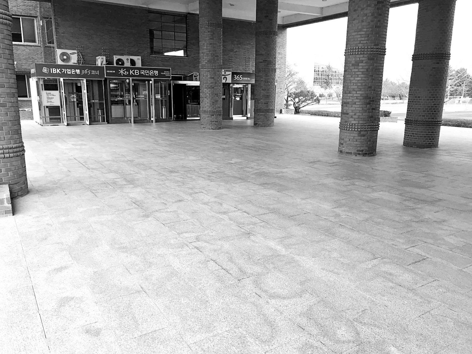
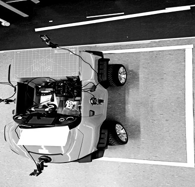
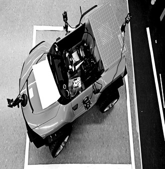
The environment used to implement the proposed system comprised an Intel (R) Core (TM) i7-7700HQ CPU, 8.00 GB RAM, and Ubuntu 16.04 OS. The experiment was conducted both indoors and outdoors to simulate an actual parking lot. Additionally, the road markings and parking bays were reduced in proportion to the vehicle. Furthermore, the distance used in the parking algorithm was also calculated and adjusted to the rotation angle and radius of the HENES T870 model. Finally, a nucleo board was used to send vehicle control signals.
III-B Evaluation
1) Autonomous Driving after Loop Closing
The control algorithm after loop closing presented in this paper was evaluated by measuring the distance covered by and steering-angle difference of the left front wheel when the vehicle returned to its original position. The experiment was performed five times at each of the three locations shown in Fig. 16.
| Place | Distance Difference (cm, ±0.5) | |||||
| Trial 1 | Trial 2 | Trial 3 | Trial 4 | Trial 5 \bigstrut | ||
|
8 | 5 | 11 | 8 | 5 \bigstrut | |
|
8 | 5 | 6 | 6 | 8 \bigstrut | |
|
5 | 7 | 12 | 8 | 11 \bigstrut | |
| Place | Angle Difference (°, ±2.5) | |||||
| Trial 1 | Trial 2 | Trial 3 | Trial 4 | Trial 5 \bigstrut | ||
|
10 | 15 | 20 | 15 | 15 \bigstrut | |
|
15 | 15 | 10 | 15 | 20 \bigstrut | |
|
15 | 10 | 15 | 15 | 10 \bigstrut | |
The results in (a) and (b) are very similar, whereas the results in (c) are slightly pronounced. This is attributed to the environment of (c) being larger than the other two environments. Furthermore, the average distance that had to be covered driving in a straight line was greater in (c) compared to that in (a) and (b). Keyframes were generated when the level of new features exceeded that exhibited in previous keyframes. However, similar features were continuously detected in straight routes. Therefore, there was a large distance gap between keyframes in straight routes. Interestingly, for straight routes, the distance between adjacent keyframes did not affect the autonomous driving. Nevertheless, the error in driving was negligible even in the case of (c).
The above results show that the algorithms presented by this study exhibit high accuracy for both indoor and outdoor environments. In other words, the error is not significant when the vehicle drives along the same path it did before the loop closing occurred, without capturing any new information but instead utilizing the information in the SLAM map.
2) Arrow Recognition Rate Experiment The experiment was conducted by reducing the size of the actual road markings by the same reduction ratio of the parking lot space. It was conducted on three regular outdoor pavements and one indoor area, with a total of 20 experimental processes, each mutually exclusive for a left or right arrow.
| Place | |||
| Outdoor 1 | Outdoor 2 | Outdoor 3 | Indoor \bigstrut |
| 85% | 80% | 90% | 70% \bigstrut |
The indoor environment presented a lower success rate than the outdoor environments. This may be because the glare on the floor caused by indoor lighting was detected during the edge detection process, hindering the correct detection of arrows. If a robust method of illumination interference is applied in the system, it may present higher success rates in the indoor environment.
3) Parking Success Rate Experiment
In this experiment, we evaluated the success of the parking algorithm based on whether the vehicle entered the parking bay correctly after locating the bay. The experiment was conducted indoors with glare on the floor and outdoors on asphalt to measure the accuracy of parking-line recognition depending on the environment. The parking bay was located only on the left side of the vehicle for repeated experiments under the same conditions.
| Place | |
| Outdoor | Indoor \bigstrut |
| 75% | 62.5% \bigstrut |
After executing the algorithm in each case, it was considered as a success if the distance between the nearest border and the vehicle exceeded 18 cm; otherwise, it was considered as a failure. This criterion was established based on the condition when the vehicle was located in the center of the parking area parallelly, considering the size of the parking bay.
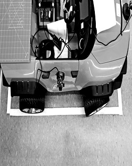
The experiments showed 62.575matching were performed effectively in both environments. Parallel alignment and detection of the end of the parking algorithm were also successfully performed in both environments. However, when the vehicle could not move to the appropriate location to reverse, the autonomous parking was unsuccessful as shown in Fig. 17. This may have resulted from poor scale estimation from SLAM and topographical maps.
IV CONCLUSION
In this paper, we proposed a system that implements autonomous parking using only camera sensors. The proposed self-driving method involves detecting parking bays and direction arrows via a fisheye camera at the front, rear, left, and right of the vehicle. During self-driving, the SLAM map was constructed by identifying the features in the image of the front camera. AVM images were utilized for parking¬ space detection. In this approach, we reduced the computational cost by using the LUT of the two pre-acquired images, rather than by directly converting the fisheye image into the AVM image. Then, when a parking space was detected, parking was executed by different parking algorithms depending on the location of the vehicle with respect to the parking space shown on the SLAM map. If the left, right, and rear cameras detected that the vehicle had entered the parking line correctly, parking maneuvers were halted.
Considering that driving route data are stored using SLAM technology, a system can be developed in the future to return the vehicle to the location where parking was initiated. Notwithstanding, the calculation of scale has not been completely automated. Moreover, the success rate of autonomous parking is not at a level sufficient for comer-cialization. This seems to be a limitation arising from the heavy reliance on cameras. In this regard, if we apply sensor fusion using other sensors such as ultrasound sensors in the system, we can expect higher accuracy and automation compared with that of the system proposed in this paper.
In conclusion, this paper contributes to the field of autonomous parking on account of asserting that it is possible to develop a self-parking system to a level where completely autonomous parking is possible.
References are important to the reader; therefore, each citation must be complete and correct. If at all possible, references should be commonly available publications.
References
- [1] M. J. Kim, H. S. Shin, and J. H. Kim, ”The Perception System based on LIDAR Sensor for Auto Valet Parking Systems,” Journal of Institute of Control, Robotics and Systems, vol. 25, no. 7, pp. 617–624, 2019.
- [2] H. Lee, D. Kim, and K. Yi, ”Steering Control Algorithm for Perpendicular Parking of Autonomous Parking System,” in KSAE 2011 Annual Conference, 2011.
- [3] R. Kummerle, D. Hahnel, D. Dolgoy, S. Thrun, and W. Burgard, ”Autonomous driving in a multi-level parking structure,” in 2009 IEEE International Conference on Robotics and Automation, 2009.
- [4] R. Mur-Artal, J. M. M. Montiel, and J. D. Tardos, “ORB-SLAM: A versatile and accurate monocular SLAM system,” IEEE Transactions on Robotics and Automation, vol. 31, no. 5, pp. 1147–1163, 2015.
- [5] Y. Wang, S. Cai, S. J. Li, Y. Liu, Y. Guo, T. Li, and M. M. Cheng, ”CubemapSLAM: A piecewise-pinhole monocular fisheye slam system,” in Computer Vision – ACCV 2018, Cham: Springer International Publishing, 2019, pp. 34–49.
- [6] K. K. Delibasis and I. Maglogiannis, “Feature extraction and pattern recognition from fisheye images in the spatial domain,” in Proceedings of the 13th International Joint Conference on Computer Vision, Imaging and Computer Graphics Theory and Applications, 2018.
- [7] E. Rublee, V. Rabaud, K. Konolige, and G. Bradski, “ORB: An efficient alternative to SIFT or SURF,” in 2011 International Conference on Computer Vision, 2011.
- [8] S. Suchitra, R. K. Satzoda, and T. Srikanthan, “Detection & classification of arrow markings on roads using signed edge signatures,” in 2012 IEEE Intelligent Vehicles Symposium, 2012.
- [9] P. V. C. Hough, ”Method and means for recognizing complex patterns,” U.S. Patent No. 3 069 654, Dec. 18, 1962.
- [10] J. Illingworth and J. Kittler, “A survey of the Hough transform,” Computer Vision, Graphics, and Image Processing, vol. 43, no. 2, p. 280, 1988.
- [11] M. Fan, Z. Hu, K. Hamada, and H. Chen, “Line filter-based parking slot detection for intelligent parking assistance system,” in Lecture Notes in Electrical Engineering, Berlin, Heidelberg: Springer Berlin Heidelberg, 2015, pp. 175–181.
- [12] R. Brunelli, Template matching techniques in computer vision: Theory and practice. Hoboken, NJ: Wiley-Blackwell, 2009.
![[Uncaptioned image]](/html/2104.13119/assets/YounggonJo.jpg) |
Young Gon Jo graduated from Handong University in 2021 with the B.S. degree of computer science and electric engineering. He currently works for the algorithm team at VADAS in Pohang, Republic of Korea. His research interest includes the image processing and autonomous driving technology. |
![[Uncaptioned image]](/html/2104.13119/assets/SeokhyeonHong.jpg) |
Seok Hyeon Hong is currently pursuing the B.S. degree in computer science and engin- eering with the School of Computer Science and Electrical Engineering, Han-dong University. Since 2019, he has been a Research Assistant with the Computer Graphics and Vision Laboratory. His current research interests include computer vision and computer graphics. |
![[Uncaptioned image]](/html/2104.13119/assets/SungsooHwang.jpg) |
Sung Soo Hwang graduated from Handong University in 2008 with a B.S. degree of electric engineering and com-puter science. He received the M.S. and Ph.D. degree in electrical and electronic engineering from the Korea Advanced Institute of Science and Technology in 2010 and 2015, respectively. He is currently an associate professor at Handong University in the School of Computer Science and Electrical Engineering. His research interest includes the creation and operation of video maps for augmented reality and autonomous driving. |
![[Uncaptioned image]](/html/2104.13119/assets/JeongmokHa.jpg) |
Jeong Mok Ha received his B.S. degree in electrical engineering from the Pusan National University, Busan, Republic of Korea, in 2010 and Ph.D. in electrical engineering from the Pohang University of Science and Technology (POSTECH), Pohang, Republic of Korea, in 2017. He is currently an algorithm team leader in VADAS Co., Ltd., Pohang, Republic of Korea. He is interested in automotive vision, including camera calibration, surround view, deep learning, and SLAM. |