Active tail flexion in concert with passive hydrodynamic forces improves swimming speed and efficiency
Abstract
Fish typically swim by periodic bending of their bodies. Bending seems to follow a universal rule; it occurs at about one-third from the posterior end of the fish body with a maximum bending angle of about . However, the hydrodynamic mechanisms that shaped this convergent design and its potential benefit to fish in terms of swimming speed and efficiency are not well understood. It is also unclear to what extent this bending is active or follows passively from the interaction of a flexible posterior with the fluid environment. Here, we use a self-propelled two-link model, with fluid-structure interactions described in the context of the vortex sheet method, to analyze the effects of both active and passive body bending on the swimming performance. We find that passive bending is more efficient but could reduce swimming speed compared to rigid flapping, but the addition of active bending could enhance both speed and efficiency. Importantly, we find that the phase difference between the posterior and anterior sections of the body is an important kinematic factor that influences performance, and that active antiphase flexion, consistent with the passive flexion phase, can simultaneously enhance speed and efficiency in a region of the design space that overlaps with biological observations. Our results are consistent with the hypothesis that fish that actively bend their bodies in a fashion that exploits passive hydrodynamics can at once improve speed and efficiency.
keywords:
Swimming, hydrodynamics, flexibility, bending rules, body deformations, vortex-sheet model1 Introduction
Millions of years of natural selection endowed fish with remarkable abilities to swim efficiently compared to underwater man-made propulsors (Sfakiotakis et al., 1999; Lauder, 2015). Several fish use body and caudal fin (BCF) deformations for propulsion. Details of BCF deformations have been used to classify fish swimming modes (Sfakiotakis et al., 1999; Shadwick & Gemballa, 2005; Low & Chong, 2010; Smits, 2019). Invariably, in most BCF swimming modes, anterior to posterior bending of the fish body seems to play an important role in swimming efficiency, and it is often linked to increased flexibility towards the fish tail or caudal peduncle (Combes & Daniel, 2003; Tytell & Lauder, 2004; Tytell et al., 2010, 2016; Gemmell et al., 2016).
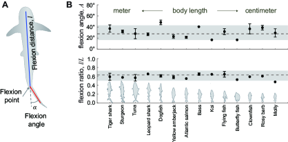
In an effort to document the bending rules of fluid-based propulsors, both aerial and aquatic, Lucas et al. (2014) collected morphometric data of the flexion parameters across length scales and animal taxa. They identified two parameters to characterize the bending behavior: flexion ratio between the flexion distance and total length of the propulsor and maximum flexion angle . They found that flexion ratio and maximum flexion angle of all surveyed animals, including fish, clustered in a limited design space: bending occurs at about of body length at maximum flexion angle of about , as shown in Figure 1 for swimming fish based on the data collected in Lucas et al. (2014). It is unclear the extent to which this anterior-to-posterior bending is active or whether it follows passively due to the interaction of a flexible posterior with the fluid motion. Either way, these findings raise the question of whether hydrodynamics could have provided a selective force for driving this convergent bending design.
To address these questions, we analyze the influence of bending on the swimming speed and efficiency of a simplified fish model that consists of anterior and posterior sections connected via a rotational joint at the flexion point (see Figure 1A). The fish anterior undergoes periodic planar pitching while the posterior either (i) moves in synchrony with the anterior as if the two parts were a single rigid body, (ii) bends actively at distinct amplitude and phase relative to the fish anterior, or (iii) bends passively due to interactions with the flow generated by the fish anterior. We find that swimming with passive bending could be more efficient than rigid flapping but at the cost of diminished swimming speed. Active bending provides more possibilities to alter the swimming performance through not only the flexion ratio and maximum flexion angle as reported in Lucas et al. (2014) but also the phase difference between the flapping motions of the anterior and posterior parts. Importantly, we find that antiphase anterior-to-posterior flexion can simultaneously enhance swimming speed and efficiency in a region of the design parameter space . Flexion ratios and angles that lead to significant improvements in speed and efficiency overlap with the observations of real fish reported in Lucas et al. (2014). We analyze in depth the hydrodynamic mechanisms underlying these improvements in swimming performance.
Details of the flow field around swimming fish have received a great deal of attention. Several studies used particle image velocimetry to measure the flow field around live fish and analyze the interplay between body deformations and thrust production; see, e.g., Müller et al. (1997, 2002); Liao et al. (2003); Tytell & Lauder (2004); Gemmell et al. (2016). In-silico models of various degrees of fidelity to fish morphology and kinematics have also been used to examine the offsets of body deformations on swimming speed and efficiency (Eldredge, 2006; Kern & Koumoutsakos, 2006; Tytell et al., 2010; Eloy, 2013). Importantly, several experimental and numerical studies have shown that plates and foils undergoing pitching or heaving motions provide good approximations of the fluid-structure interactions in swimming fish (Blondeaux et al., 2005; Wen & Lauder, 2013; Lauder et al., 2011; Menon & Mittal, 2019); including the reverse von Kármán vortex wake left behind swimming fish and flapping foils (Taneda, 1965; Triantafyllou & Triantafyllou, 1993).
A variety of fluid-structure interaction models have been proposed to analyze the effect of body flexibility on bending in flows; see, e.g., Shelley & Zhang (2011) and references therein. Here, we present a brief literature review focused on this topic. Heathcote & Gursul (2007) conducted experiments on a flapper with a rigid leading edge and flexible tail fixed in a water channel and found that flexibility can enhance both efficiency and thrust production. Eldredge (2008) and Eldredge et al. (2010) numerically simulated the flapping motion of articulated rigid links and found that joint flexibility can reduce the power required for flapping. Alben (2008) used a filament of uniform flexibility to model the tail of swimming fish in the context of the vortex sheet method and predicted enhancement in efficiency rather than thrust when choosing parameters (dimensionless rigidity and reduced pitching frequency) that are consistent with biological data. Quinn et al. (2015) conducted a large set of experiments on two-dimensional pitching and heaving flexible plates at various stiffness values, kinematic parameters, and incoming flow speeds. By combining grid search and gradient-based optimization methods, they found that optimizing the pitching angle with heaving can almost double the propulsor efficiency compared to heave-only motions. Hoover et al. (2018) conducted simulations combining three-dimensional Navier-Stokes equation with one-dimensional Euler–Bernoulli beam theory to analyze the motion of heaving flexible plates, and identified local peaks in swimming speed over a parameter space consisting of the beam material property and heaving frequency. Also using three-dimensional simulations of pitching plates of uniform flexibility, Dai et al. (2012) found that the phase delay between the leading and trailing edge of the plate decreases with increasing stiffness . For large stiffness, the plate moves in no-neck mode (in-phase in our notation), in which thrust production is close to that of a rigid pitching plate with similar trailing edge displacement.
The effect of uniform flexibility on swimming speed, thrust generation, swimming energetics, and stability have been analyzed in numerous other experimental and computational studies; see, e.g., Shoele & Mittal (2016); Feilich & Lauder (2015); Michelin & Llewellyn Smith (2009); Miao & Ho (2006); Combes & Daniel (2001); Hua et al. (2013); Wang (2020); Ryu et al. (2019). Specifically, Liu & Bose (1997); Heathcote et al. (2008); Tangorra et al. (2010) have indicated that flexibility could lessen or prevent thrust production. Flexible propulsors have also been widely used in man-made biomimetic underwater autonomous vehicles (UAV); see, e.g., Fujiwara & Yamaguchi (2017); Katzschmann et al. (2018); Gibouin et al. (2018); Zhu et al. (2019); White et al. (2021). Most notable is the Tunabot design of Zhu et al. (2019) and White et al. (2021) which mimics the shape and bending kinematics of yellowfin tuna (Thunnus albacares) and Atlantic mackerel (Scomber scombrus).
While most studies have focused on uniformly flexible bodies, Combes & Daniel (2003) and Lucas et al. (2014) noted that the stiffness along the fish body is not uniform, but decreases towards the tail, and that the propulsor becomes highly flexible at the flexion point of the body; see Figure 1(A). To explore the effects of non-uniform flexibility on efficiency and thrust production, Lucas et al. (2015) considered flexible plates of inhomogeneous stiffness undergoing heaving and pitching motions in a water tunnel and found that non-uniform stiffness can improve thrust production, and that in order to achieve optimal propulsion, the morphologic factor (flexion ratio) and kinematic factor (motion type and motion parameters) should be considered simultaneously. Vincent et al. (2020a, b) analyzed the effect of non-uniform flexibility on flight performance in the context of a tumbling wing model, and found that wing tip flexibility that follows the empirical rules reported in Lucas et al. (2014) leads to improved flight performance.
In this paper, we use a simplified two-link fish model to analyze the influence of active and passive bending on the swimming speed and efficiency. Two link models are commonly used to study the effect of flexibility on the performance of flapping bodies (Eldredge et al., 2010; Wan et al., 2012; Li et al., 2015). We solve for fluid-structure interactions in the context of the vortex sheet method as described in Section 2. The vortex sheet model has been used extensively to analyze problems of fluid-structure interactions, including ring formation at the edge of a circular tube (Nitsche & Krasny, 1994) and wakes of oscillating plates (Jones, 2003; Sheng et al., 2012), falling cards (Jones & Shelley, 2005), flapping flexible flags (Alben, 2008, 2009), swimming plates (Wu, 1971), hovering flyers (Huang et al., 2016, 2018) and schooling of swimming plates (Heydari & Kanso, 2020). Here, we use the implementation of Nitsche & Krasny (1994). In Section 3, we report the effects of both active and passive bending on the swimming performance of sinusoidally pitching swimmers compared to rigid flapping. In Section 4, we discuss these findings in the context of existing work and highlight the implications of our results on the design of underwater autonomous vehicles.
2 Problem formulation
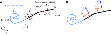
We model the flexible swimmer as a planar two-link body of total length , negligible thickness , and total mass per unit depth , where is both the swimmer and fluid density, assuming a neutrally-buoyant fish. The flexion point indicates where the anterior link (of length ) is joined to the posterior link; see Figure 1(A). The anterior link undergoes sinusoidal pitching motion , where is the angle relative to the swimming direction, taken to be parallel to the -axis. Here, is the flapping amplitude, the flapping frequency, and the flapping period. When the posterior is connected rigidly to the anterior link at zero flexion, the posterior motion is equal to and the flexion angle is identically zero for all time. The two links form a single rigid plate (Figure 2A) whose swimming motion due to sinusoidal pitching has been extensively analyzed (Jones, 2003; Sheng et al., 2012; Moored & Quinn, 2019; Heydari & Kanso, 2020; Labasse et al., 2020). To explore the effects of body bending on swimming, we consider two cases: (i) active bending where the flexion angle is controlled by the swimmer, and (ii) passive bending where the flexion angle is dictated by the physics of fluid-structure interactions.
When the two-link swimmer bends actively, we allow the anterior link to have a phase advantage of magnitude relative to the flapping motion of the posterior link. At , both anterior and posterior links flap in phase and the swimmer bends in the direction of flapping (Figure 2B); for , they flap antiphase resulting in bending in the opposite direction to the anterior pitching motion (Figure 2C). The flexion angle follows a Jacobi elliptic sine function , where is the maximum flexion angle and is the elliptic modulus that controls the shape of the elliptic sine function. As , the elliptic sine function tends to a sinusoidal function and as , it approaches a square wave shape. The parameter is introduced to ensure that the flapping frequency of the posterior link is the same as that of the anterior link ( is related to the elliptic modulus via the elliptic integral and it is given by in Matlab). In this paper, without other specification, we fix and explore the effects of the anterior-to-posterior phase difference , flexion ratio , and maximum flexion angle on the swimming performance.
We write the equations governing the self-propelled motion of the two-link swimmer in non-dimensional form. To this end, we scale all parameter values using as the characteristic length scale, as the characteristic time scale, and as the characteristic mass per unit depth. Accordingly, velocities are scaled by , forces by , moments by , and power by . The equation of motion governing the free swimming is given by Newton’s second law
| (1) |
Here, and denote the components of the hydrodynamic pressure and drag forces and in the swimming direction. Specifically, is the total force normal to the swimmer due to hydrodynamic pressure and is the force tangential to the swimmer due to skin drag. The hydrodynamic pressure force is calculated in the context of the inviscid vortex sheet model (Nitsche & Krasny, 1994; Huang et al., 2016, 2018; Heydari & Kanso, 2020), and the drag force is introduced to emulate the effect of fluid viscosity (Fang, 2016; Ramananarivo et al., 2016). A brief overview of the vortex sheet method and its numerical implementation is given in Appendix A and C. Detailed expressions of the fluid forces acting on the swimmer are given in Appendix B.
When the swimmer bends passively, the relative rotation of the posterior end is not prescribed a priori and follows from the physics of fluid-structure interactions. Considering that the rotational joint at the flexion point is equipped with a torsional spring of stiffness and damping coefficient , we write the equation governing the rotational motion of the posterior link
| (2) |
where and are the moment of inertia and hydrodynamic moment acting on the posterior link about the flexion point, is an inertial moment that arises because the flexion point about which the moments are balanced is moving; see details in Appendix B.
To assess the swimming performance of the two-link swimmer, we introduce five metrics: the period-average swimming speed at steady state, the thrust force , the period-average input power required to maintain the prescribed flapping motions, and the propulsion efficiency defined as the kinetic energy of the swimmer divided by the input work over one flapping period; see Appendix B for more details.
3 Results
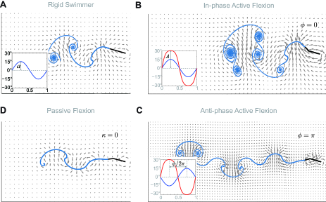
We compare the free swimming that results from flapping while undergoing active and passive bending to that of rigidly flapping. All swimmers have the same total length and undergo the same sinusoidal pitching motion about their leading edge with and , albeit exhibiting distinct bending patterns. Figure 2 shows snapshots of the wake represented by the free vortex sheet and velocity field generated by a swimmer undergoing (A) rigid flapping, (B) in-phase active bending with flexion amplitude and flexion ratio , (C) antiphase active bending at the same flexion amplitude and ratio, and (D) passive bending. All snapshots are taken at the same instant in the flapping cycle (at after steady state has been reached). Compared to the rigid swimmer, in-phase flexion produces wider wakes and larger leading edge circulation and instantaneous flow speeds, while antiphase flexion is characterized by a leaner, longer wake with weaker leading edge circulation and lower flow speeds. The main features of the instantaneous flow during antiphase flexion, namely, the leaner wake and weaker leading edge circulation are also observed in passive bending of the swimmer body. These flow features are important for the hydrodynamic forces exerted on the swimmer as discussed later.
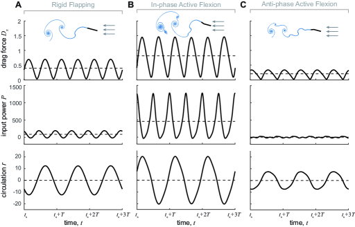
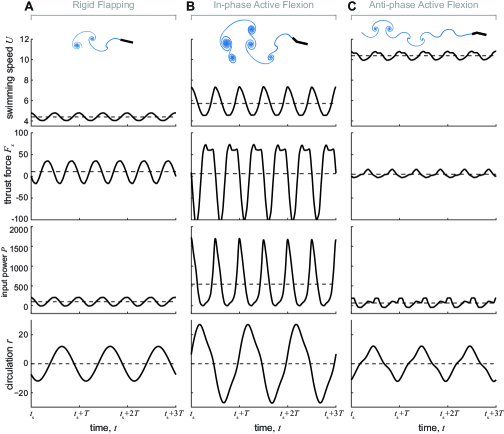
We quantitatively evaluate the steady state motion of the rigid and actively-bending swimmers in Figure 2(A-C). In Figure 3, from top to bottom, we report the instantaneous (solid lines) and period-average (dashed lines) values of the swimming speed, thrust force, input power, and circulation. On average, rigid flapping produces the lowest swimming speed while antiphase flexion the highest. Fluctuations around the average swimming speed are smallest for the swimmer undergoing antiphase flexion. The discrepancy in average swimming speeds between the three flapping modes is surprising at first sight given that the average values of the thrust force are comparable. However, a closer look at the instantaneous thrust shows that the swimmer undergoing antiphase flexion hardly experiences negative thrust over its flapping cycle. In-phase flexion leads to negative thrust of high magnitudes over larger subintervals of the flapping cycle, as highlighted further in Figure 4. Consequently, the required input power for in-phase flexion is largest compared to both rigid flapping and antiphase flexion. This is also true of the overall wake circulation. It is worth noting that, by Kelvin’s circulation theorem, circulation around the leading edge must be equal to the overall circulation in the wake. Therefore, compared to rigid flapping, in-phase flexion increases the circulation around the leading edge of the swimmer while antiphase flexion decreases leading edge circulation as noted qualitatively in Figure 2.
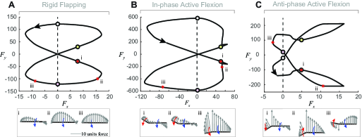
The results in Figure 3 indicate that the swimmer undergoing antiphase flexion achieves higher swimming speed at lower power requirement and energetic cost. To elucidate the hydrodynamic forces at play, we report in Figure 4 the force hodograph defined as a plot of the lateral pressure force versus thrust acting on each swimmer. Snapshots of the distribution of hydrodynamic pressure forces along the swimmers are depicted in bottom row of Figure 4, and indicate that the -component of the forces on the anterior and posterior sections during antipase flexion act opposite to each other as in a tug-of-war, leading to overall reduction in thrust values. Importantly, antiphase flexion also reduces the lateral force and negative thrust, with negative thrust experienced only over a small subinterval of the flapping period, as noted earlier. In contrast, in-phase flexion significantly increases the lateral force and negative thrust.
To explain the effect of flexion on the lateral force experienced by the swimmer, it is instructive to re-examine the flow field around the rigid and actively-bending swimmers in Figure 2(A-C). A large leading edge vortex (LEV) is known to generate large lift in flapping flight; see, e.g., Ellington (1984); Dickinson et al. (1999). In swimming, larger leading edge circulation creates larger lateral force, which explains why, compared to rigid flapping, in-phase flexion increases the lateral force acting on the swimmer while antiphase flexion decreases it. Lift is beneficial for flight but large lateral forces are detrimental to swimming speed, as noted in Drucker & Lauder (2000) for fish and recapitulated here in the context of our swimmer model.
To further analyze the difference in the swimming performance between rigid flapping and flapping with inphase and antiphase active bending, we fix the swimmer in an oncoming uniform flow of speed and we compute the hydrodynamic drag forces in each case. In Figure 5, we report the drag force, input power, and circulation in the wake of the fixed swimmer. Compared to rigid flapping, antiphase flexion reduces instantaneous drag, power, and circulation, while in-phase flexion increases all three quantities. Reduced drag implies lower thrust requirement during steady state swimming, which provides another perspective for understanding the improved performance of antiphase flexion.
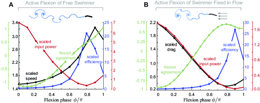
We next examine the period-average performance of actively bending swimmers as a function of anterior-to-posterior phase difference . In Figure 6(A), we consider the case of free swimming, we fix the flexion ratio and flexion amplitude , and we plot the swimming speed , input power and efficiency versus , all scaled by the corresponding values of a rigidly flapping swimmer , , , respectively. We find that active bending is always beneficial in terms of enhanced speed relative to rigid flapping, albeit at an increased power requirement. Importantly, as the anterior-to-posterior bending changes from in-phase flexion to flexion at a phase lag, the scaled speed increases and the scaled power requirement decreases. Optimal performance occurs at and in terms of maximum swimming speed and minimum input power and maximum efficiency, respectively. In Figure 6(B), we fix the swimmer in oncoming flow of uniform speed and compute the scaled drag force , input power and efficiency as a function of scaled by the corresponding values of a fixed rigid flapper. Analogous to the free swimmer, drag and input power are minimal at . Taken together, the results imply that antiphase active flexion is near optimal for enhancing speed and efficiency and reducing drag force and power requirement.
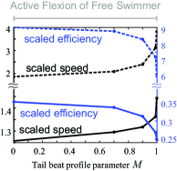
To complete this analysis, we also explored the effect of the flapping parameter on the swimming performance. We found that for a fixed phase, the swimming speed and efficiency change monotonically with with maximum speed and minimum efficiency as ; see Figure B in the Appendix. That is, reversing the bending direction with a quick flicker improves speed at the cost of decreasing efficiency.
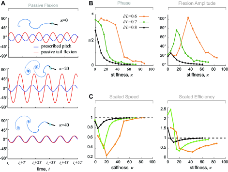
Is active bending necessary for obtaining this enhancement in swimming speed and efficiency over rigid flapping? To address this question, we examine the free swimming of a passively bending swimmer, where the posterior end flaps passively under the effect of hydrodynamic forces and moments generated by the pitching motion of the anterior section. Elastic forces due to a spring of stiffness located at the flexion point are also at play. In Figure 7(A), we keep all parameter values the same as those used for the actively bending swimmer, and, from top to bottom, we report the flapping motions of the anterior and posterior ends for stiffness values , , and . At zero stiffness, flexion introduces no restoring forces and moments. The posterior part rotates antiphase relative to the flapping motion of the anterior part, at an amplitude comparable to the anterior pitching amplitude. The associated wake, shown in Figure 2(D) and represented by the free vortex sheet in the inset of Figure 7(A), shares similar features to the wake obtained during antiphase active flexion. At moderate spring stiffness , the flexion amplitude increases (), and the wake also exhibits larger lateral dispersion. At large stiffness , the posterior part rotates in-phase with the anterior part at the same flapping amplitude in a way reminiscent to rigid flapping; as reported in Dai et al. (2012) for flexibble pitching plates.
The relative motion of the posterior part is close to a sinusoidal function for all stiffness values . Therefore, for each value, we fit by a sine function using a standard algorithm (Moré & Sorensen, 1983). For all fitting, we have at least confidence and frequency , thus ensuring convergence of the fitting. In Figure 7(B), we report the fitted flexion amplitude and phase difference as a function of spring stiffness for three distinct flexion ratios , and . We find that for all , as stiffness increases, the phase difference decreases monotonously from to implying that the posterior flapping motion changes from antiphase to in-phase. The maximum flexion angle first increases with increasing , then decreases to nearly zero at large stiffness implying rigid flapping of both anterior and posterior ends.
We compute the associated swimming speed and efficiency for each stiffness value and we scale the results by those of a rigid swimmer; see Figure 7(C). Clearly, the swimmer with passive flexion never surpasses the swimming speed of a rigid swimmer. At very low stiffness (), passive flexion results in a swimming speed close to that of rigid flapping while doubling the swimming efficiency. The increase in swimming efficiency at small stiffness comes purely from a decrease in power requirement compared to rigid flapping. This is in contrast to active flexion where the enhancement in swimming speed and efficiency noted in Figure 6 comes at an increase in power requirement relative to rigid flapping. As increases, the scaled swimming speed and propulsion efficiency decrease, indicating that moderate flexibility is detrimental to both speed and efficiency. For large , the speed and efficiency converge to the same speed and efficiency as the rigid swimmer, consistent with the results of Dai et al. (2012). We repeat this analysis for three flexion ratios , , . The scaled speed seems to increase monotonically with increasing , but the scaled efficiency seems to peak at but only for a range of small values. These findings imply that, unlike flapping insect wings (Ellington, 1985; Huang et al., 2015), restoring elastic forces seem to be detrimental to swimming performance. Swimming efficiency peaks at low stiffness values when the restoring spring forces are weak and the posterior end is driven passively by the fluid forces.
Could the swimmer learn from passive flexion to improve its performance by bending actively in a way that exploits the hydrodynamic forces generated naturally during passive flexion? The results in Figures 2-6 for actively bending swimmers suggest that maximum benefit occurs for near anti-phase flexion, whereas the results in Figure 7 show that maximum efficiency for passively bending swimmers occurs for zero stiffness for which the posterior bends anti-phase. Importantly, the main features of the instantaneous flow during antiphase active flexion (Figure 2C) are also observed in passive bending at zero stiffness (Figure 2D). We thus posit that active bending is most beneficial when the swimmer actively beats its tail in a direction that takes advantage of the natural flows that arise during passive bending. To test this hypothesis, we define a flexion agreement parameter that aims to relate passive and active bending. Starting from a swimmer bending passively at zero spring stiffness (Figures 2D and 7A), we assume a hypothetical posterior that is actively flapping about the flexion point of the swimmer at a relative angle . We compute the fluid velocity induced by the passively-bending swimmer along the hypothetical posterior section that is bending actively (here, is the distance from the flexion point). The flexion agreement parameter is given by
| (3) |
where is the relative velocity of the hypothetical actively-flapping posterior. Positive values of the flexion agreement parameter imply a beneficial interaction between the flow generated during passive flexion and the velocity of the hypothesized posterior during active flexion, whereas negative values indicate a detrimental one.
In Figure 6(A), we set to be equal to the maximum flexion angle of the passively-bending swimmer, and we vary from to . We find that the agreement parameter , normalized by its maximum value, is largest for antiphase active flexion and smallest near in-phase active flexion. This result indicates that antiphase active flexion matches the local flow created during passive flexion best, whereas in-phase active flexion acts opposite to these flows. That is, the swimmer during antiphase flexion can utilize better the flow field generated by the pitching motion of its anterior section, and thus it can achieve higher swimming speed and efficiency compared to in-phase flexion.
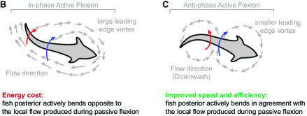
To emphasize the effect of the interaction between the flow field and kinematics of active flexion on swimming performance, we schematically summarize the two cases of in-phase and antiphase flexion in Figure 8. During in-phase active flexion, the flow field is characterized by a strong leading edge vortex around the anterior section of the fish and large lateral forces. Further, the posterior part bends opposite to the local flow field of a passively bending swimmer. During antiphase active flexion, the leading edge vortex is smaller and it is followed by a counter-rotating vortex around the fish mid-section such that the posterior part is moving in synchrony with the downwash flow induced by this counter-rotating vortex. The flow field is helping the motion of the posterior end. These results indicate that active body deformation that are in agreement with local flows produced during passive deformations are more advantageous for enhancing swimming speeds and efficiencies.
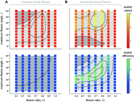
Lastly, we explore the effect of maximum flexion angle and flexion ratio on the period-average values of the swimming speed and efficiency for both in-phase and antiphase active flexion. Specifically, we examine the range and for and . In Figure 9, we report the period-average values normalized by the corresponding values for a rigid swimmer with pitching amplitude equal to the anterior part amplitude. We highlight in light and dark grey respectively the regions in the parameter space where the flexible swimmer outperforms and underperforms the rigid swimmer. The swimmer with in-phase flexion swims slower than the rigid swimmer for small flexion ratios () and high flexion amplitudes (), and swims faster than rigid swimmer otherwise. This swimmer, however, is always less efficient than the rigid swimmer for reasons explained previously. In Figure 9(B), for most parameter values, the antiphase swimmer outperforms the rigid swimmer in terms of swimming speed and efficiency. Note that the region with the highest swimming speed advantage lies in and , and the region with the highest efficiency advantage lies in and .
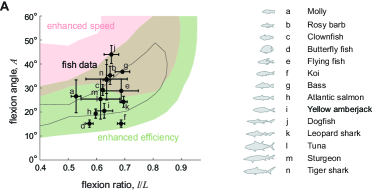
We compare the regions of highest swimming speed and efficiency obtained during antiphase flexion in Figure 9(B) to the design parameters of biological fish reported in Figure 1. In Figure 10, we plot the flexion angle as a function of the flexion ratio for the fish data in Figure 1 and we superimpose on this design space the regions of 200% enhancement in speed and 300% enhancement in efficiency from Figure 9(B). As shown in Figure 10, there is significant overlap between these regions of improved performance and the biological data. Indeed, all biological data lie within the region of improved efficiency.
Many of these fish are known to exhibit migratory behavior that requires efficient swimming. Even baby clownfish are reported to migrate over long distances (Simpson et al., 2014). Tuna can cover km in one traveling phase (Itoh et al., 2003) and tiger shark are capable of traveling long distances in short time (Simpfendorfer, 2009). Our results in Figure 10 are consistent with these facts: tiger shark and clownfish lie in the intersection region of improved speed and efficiency, and tuna lies in the region with highest increase in efficiency. On the hand, butterflyfish, who are only known to migrate over short distances during spawning (Yabuta, 1997), and Koi, for which there is no evidence of migration, lie in the regions characterized by smaller increase in speed and efficiency.
4 Conclusion
We analyzed the swimming performance of flapping swimmers undergoing active and passive deformations. Whereas fish exhibit a variety of swimming modes Sfakiotakis et al. (1999), we simplified body deformations to account for only anterior-to-posterior bending, with one degree of freedom describing the relative rotation between the two sections. We explored the effects of morphological and kinematic parameters on the swimming speed and efficiency.
We found that passive body bending, at negligible body stiffness and minor elastic forces, caused anterior-to-posterior antiphase flexion. This antiphase flexion is dictated by the flow physics and causes the swimmer’s morphology to get more streamlined compared to rigid flapping with no flexion, thus creating leaner wakes that reduce drag and power requirement and increase efficiency. While drag reduction is desirable for improved efficiency, passive bending also reduced thrust production, thus diminishing swimming speed. Interestingly, restoring elastic forces at moderate stiffness values seemed detrimental to both swimming speed and efficiency. These findings are consistent with the hypothesis that for maximum efficiency, the fish tail and posterior body should flex like water, exhibiting little or no resistance to the flows generated by the flapping motion of the anterior portion of the body. This hypothesis could explain how anesthetized fish, with no muscle activity, placed in periodic wakes generate oscillatory body deformations that allow the fish to swim upstream (Beal et al., 2006).
We also found that a swimmer that actively creates antiphase anterior-to-posterior bending enjoyed the same benefits of leaner wake and reduced drag as a passively bending swimmer while mitigating the reduction in thrust and swimming speed. To quantify the hydrodynamic mechanisms leading to this improved swimming performance, we introduced a flexion agreement parameter that compares the active flexion velocity of the swimmer’s posterior to the local flow velocity during passive flexion. We found that during active in-phase flexion, the posterior beats opposite to the local flow that would naturally arise during passive flexion, leading to a negative flexion agreement parameter, and thus lower swimming speed and efficiency. During active antiphase flexion, the posterior flaps consistently with the local flow, leading to a positive flexion agreement parameter, and improved speed and efficiency.
These findings suggest tremendous versatility in swimming performance, even when accounting only for coarse anterior-to-posterior bending motions. They indicate that fish can readily and fluidly transition from efficient (passive bending) to fast (active bending) by actively beating their tail in agreement with the local flow generated during passive bending.
To explore the role of flow physics on the convergent bending rules of (Lucas et al., 2014), we examined the effect of flexion ratio and maximum flexion angle on the performance of swimmers undergoing active antiphase anterior-to-posterior bending. We found an optimal region in this design space that simultaneously enhances swimming speed and efficiency. Importantly, we found that this region has a significant overlap with the fish bending parameters reported in (Lucas et al., 2014); see Figure 8(A). In fact, all biological data fell in the region of enhanced efficiency predicted by our model.
Taken together, our results have two major implications on understanding the role of body bending in fish swimming. They are consistent with the hypothesis that fish that actively bend their bodies in a fashion that exploits the local hydrodynamics can at once improve speed and efficiency. They also support the hypothesis that flow physics could have provided a selective force for driving the evolution of fish bending patterns.
Beyond the trade-offs between speed and efficiency explored here, our model could be generalized in future studies to examine transient swimming maneuvers such as turning. Pollard & Tallapragada (2019) proposed that a passive posterior not only improves efficiency, but also improves fish maneuverability compared to a rigid body. Drucker & Lauder (2000) pointed out that although large lateral forces are detrimental to fish swimming speed, they can improve fish maneuverability. Our model predicts large lateral forces during in-phase active flexion, suggesting that this bending pattern, while not optimal for forward swimming, could be beneficial for turning motions. These considerations, as well as models of higher fidelity to the fish biomechanics and fluid environment, will be explored in future research.
Finally, our finding that active body bending and tailbeat patterns that match local flow velocities that would be produced naturally by anterior sections of the fish body could lead to improved performance and energy savings might have important implications on understanding the mechanisms driving body and caudal fin deformations in swimming (Ramakrishnan et al., 2011; Bozkurttas et al., 2007), schooling (Heydari & Kanso, 2020; Becker et al., 2015; Li et al., 2020), and navigating ambient unsteady flows (Liao et al., 2003).
References
- Alben (2008) Alben, Silas 2008 Optimal flexibility of a flapping appendage in an inviscid fluid. Journal of Fluid Mechanics 614, 355–380.
- Alben (2009) Alben, Silas 2009 Wake-mediated synchronization and drafting in coupled flags. Journal of Fluid Mechanics 641, 489–496.
- Beal et al. (2006) Beal, DN, Hover, FS, Triantafyllou, MS, Liao, JC & Lauder, George V 2006 Passive propulsion in vortex wakes. Journal of Fluid Mechanics 549, 385.
- Becker et al. (2015) Becker, Alexander D, Masoud, Hassan, Newbolt, Joel W, Shelley, Michael & Ristroph, Leif 2015 Hydrodynamic schooling of flapping swimmers. Nature communications 6 (1), 1–8.
- Blondeaux et al. (2005) Blondeaux, Paolo, Fornarelli, Francesco, Guglielmini, Laura, Triantafyllou, Michael S. & Verzicco, Roberto 2005 Numerical experiments on flapping foils mimicking fish-like locomotion. Physics of Fluids 17 (11), 113601, arXiv: https://doi.org/10.1063/1.2131923.
- Bozkurttas et al. (2007) Bozkurttas, Meliha, Dong, Haibo, Mittal, Rajat, Tangorra, James, Hunter, Ian, Lauder, George & Madden, Peter 2007 Cfd-based analysis and design of biomimetic flexible propulsor for autonomous underwater vehicles. In 37th AIAA Fluid Dynamics Conference and Exhibit, p. 4213.
- Combes & Daniel (2001) Combes, SA & Daniel, TL 2001 Shape, flapping and flexion: wing and fin design for forward flight. Journal of Experimental Biology 204 (12), 2073–2085.
- Combes & Daniel (2003) Combes, SA & Daniel, TL 2003 Flexural stiffness in insect wings ii. spatial distribution and dynamic wing bending. Journal of Experimental Biology 206 (17), 2989–2997.
- Dai et al. (2012) Dai, Hu, Luo, Haoxiang, de Sousa, Paulo J. S. A. Ferreira & Doyle, James F. 2012 Thrust performance of a flexible low-aspect-ratio pitching plate. Physics of Fluids 24 (10), 101903, arXiv: https://doi.org/10.1063/1.4764047.
- Dickinson et al. (1999) Dickinson, Michael H., Lehmann, Fritz-Olaf & Sane, Sanjay P. 1999 Wing rotation and the aerodynamic basis of insect flight. Science 284 (5422), 1954–1960, arXiv: https://science.sciencemag.org/content/284/5422/1954.full.pdf.
- Drucker & Lauder (2000) Drucker, E.G. & Lauder, G.V. 2000 A hydrodynamic analysis of fish swimming speed: wake structure and locomotor force in slow and fast labriform swimmers. Journal of Experimental Biology 203 (16), 2379–2393, arXiv: https://jeb.biologists.org/content/203/16/2379.full.pdf.
- Eldredge (2006) Eldredge, Jeff D 2006 Numerical simulations of undulatory swimming at moderate reynolds number. Bioinspiration & biomimetics 1 (4), S19.
- Eldredge (2008) Eldredge, Jeff D. 2008 Dynamically coupled fluid–body interactions in vorticity-based numerical simulations. Journal of Computational Physics 227 (21), 9170 – 9194, special Issue Celebrating Tony Leonard’s 70th Birthday.
- Eldredge et al. (2010) Eldredge, Jeff D., Toomey, Jonathan & Medina, Albert 2010 On the roles of chord-wise flexibility in a flapping wing with hovering kinematics. Journal of Fluid Mechanics 659, 94–115.
- Ellington (1984) Ellington, C. P. 1984 The aerodynamics of hovering insect flight. vi. lift and power requirements. Philosophical Transactions of the Royal Society of London. Series B, Biological Sciences 305 (1122), 145–181.
- Ellington (1985) Ellington, Charles P 1985 Power and efficiency of insect flight muscle. Journal of Experimental Biology 115 (1), 293–304.
- Eloy (2013) Eloy, Christophe 2013 On the best design for undulatory swimming. J. Fluid Mech 717 (25), 002.
- Fang (2016) Fang, Fang 2016 Hydrodynamic interactions between self-propelled flapping wings. PhD thesis, New York University.
- Feilich & Lauder (2015) Feilich, Kara L & Lauder, George V 2015 Passive mechanical models of fish caudal fins: effects of shape and stiffness on self-propulsion. Bioinspiration & Biomimetics 10 (3), 036002.
- Fujiwara & Yamaguchi (2017) Fujiwara, Shinpei & Yamaguchi, Satoru 2017 Development of fishlike robot that imitates carangiform and subcarangiform swimming motions. Journal of Aero Aqua Bio-mechanisms 6 (1), 1–8.
- Gemmell et al. (2016) Gemmell, Brad J., Fogerson, Stephanie M., Costello, John H., Morgan, Jennifer R., Dabiri, John O. & Colin, Sean P. 2016 How the bending kinematics of swimming lampreys build negative pressure fields for suction thrust. Journal of Experimental Biology 219 (24), 3884–3895, arXiv: https://jeb.biologists.org/content/219/24/3884.full.pdf.
- Gibouin et al. (2018) Gibouin, Florence, Raufaste, Christophe, Bouret, Yann & Argentina, Médéric 2018 Study of the thrust–drag balance with a swimming robotic fish. Physics of Fluids 30 (9), 091901, arXiv: https://doi.org/10.1063/1.5043137.
- Heathcote & Gursul (2007) Heathcote, S. & Gursul, I. 2007 Flexible flapping airfoil propulsion at low reynolds numbers. AIAA Journal 45 (5), 1066–1079, arXiv: https://doi.org/10.2514/1.25431.
- Heathcote et al. (2008) Heathcote, Sam, Wang, Z & Gursul, Ismet 2008 Effect of spanwise flexibility on flapping wing propulsion. Journal of Fluids and Structures 24 (2), 183–199.
- Heydari & Kanso (2020) Heydari, Sina & Kanso, Eva 2020 School cohesion, speed, and efficiency are modulated by the swimmers flapping motion. arXiv preprint arXiv:2009.12715 .
- Hoover et al. (2018) Hoover, Alexander P, Cortez, Ricardo, Tytell, Eric D & Fauci, Lisa J 2018 Swimming performance, resonance and shape evolution in heaving flexible panels. Journal of Fluid Mechanics 847, 386–416.
- Hua et al. (2013) Hua, Ru-Nan, Zhu, Luoding & Lu, Xi-Yun 2013 Locomotion of a flapping flexible plate. Physics of Fluids 25 (12), 121901, arXiv: https://doi.org/10.1063/1.4832857.
- Huang et al. (2015) Huang, Yangyang, Nitsche, Monika & Kanso, Eva 2015 Stability versus maneuverability in hovering flight. Physics of Fluids 27 (6), arXiv: 1411.6764.
- Huang et al. (2016) Huang, Yangyang, Nitsche, Monika & Kanso, Eva 2016 Hovering in oscillatory flows. Journal of Fluid Mechanics 804, 531–549, arXiv: 1512.01505.
- Huang et al. (2018) Huang, Yangyang, Ristroph, Leif, Luhar, Mitul & Kanso, Eva 2018 Bistability in the rotational motion of rigid and flexible flyers. Journal of Fluid Mechanics 849, 1043–1067, arXiv: 1709.09241.
- Itoh et al. (2003) Itoh, Tomoyuki, Tsuji, Sachiko & Nitta, Akira 2003 Migration patterns of young pacific bluefin tuna (thunnus orientalis) determined with archival tags. Fishery Bulletin 101 (3), 514–534.
- Jones (2003) Jones, Marvin A. 2003 The separated flow of an inviscid fluid around a moving flat plate. Journal of Fluid Mechanics 496 (496), 405–441.
- Jones & Shelley (2005) Jones, Marvin A. & Shelley, Michael J. 2005 Falling cards. Journal of Fluid Mechanics 540, 393–425.
- Katzschmann et al. (2018) Katzschmann, Robert K, DelPreto, Joseph, MacCurdy, Robert & Rus, Daniela 2018 Exploration of underwater life with an acoustically controlled soft robotic fish. Science Robotics 3 (16).
- Kern & Koumoutsakos (2006) Kern, Stefan & Koumoutsakos, Petros 2006 Simulations of optimized anguilliform swimming. Journal of Experimental Biology 209 (24), 4841–4857, arXiv: https://jeb.biologists.org/content/209/24/4841.full.pdf.
- Labasse et al. (2020) Labasse, Jérémie, Ehrenstein, Uwe & Meliga, Philippe 2020 Numerical exploration of the pitching plate parameter space with application to thrust scaling. Applied Ocean Research 101, 102278.
- Lauder (2015) Lauder, George V. 2015 Fish locomotion: Recent advances and new directions. Annual Review of Marine Science 7 (1), 521–545, pMID: 25251278, arXiv: https://doi.org/10.1146/annurev-marine-010814-015614.
- Lauder et al. (2011) Lauder, George V, Lim, Jeanette, Shelton, Ryan, Witt, Chuck, Anderson, Erik & Tangorra, James L 2011 Robotic models for studying undulatory locomotion in fishes. Marine Technology Society Journal 45 (4), 41–55.
- Li et al. (2015) Li, Chengyu, Dong, Haibo & Liu, Geng 2015 Effects of a dynamic trailing-edge flap on the aerodynamic performance and flow structures in hovering flight. Journal of Fluids and Structures 58, 49–65.
- Li et al. (2020) Li, Liang, Nagy, Máté, Graving, Jacob M, Bak-Coleman, Joseph, Xie, Guangming & Couzin, Iain D 2020 Vortex phase matching as a strategy for schooling in robots and in fish. Nature communications 11 (1), 1–9.
- Liao et al. (2003) Liao, James C, Beal, David N, Lauder, George V & Triantafyllou, Michael S 2003 Fish exploiting vortices decrease muscle activity. Science 302 (5650), 1566–1569.
- Liu & Bose (1997) Liu, Pengfei & Bose, Neil 1997 Propulsive performance from oscillating propulsors with spanwise flexibility. Proceedings of the Royal Society of London. Series A: Mathematical, Physical and Engineering Sciences 453 (1963), 1763–1770.
- Low & Chong (2010) Low, KH & Chong, CW 2010 Parametric study of the swimming performance of a fish robot propelled by a flexible caudal fin. Bioinspiration & Biomimetics 5 (4), 046002.
- Lucas et al. (2014) Lucas, Kelsey N, Johnson, Nathan, Beaulieu, Wesley T, Cathcart, Eric, Tirrell, Gregory, Colin, Sean P, Gemmell, Brad J, Dabiri, John O & Costello, John H 2014 Bending rules for animal propulsion. Nature Communications 5 (1), 3293.
- Lucas et al. (2015) Lucas, Kelsey N, Thornycroft, Patrick J M, Gemmell, Brad J, Colin, Sean P, Costello, John H & Lauder, George V 2015 Effects of non-uniform stiffness on the swimming performance of a passively-flexing, fish-like foil model. Bioinspiration & Biomimetics 10 (5), 056019.
- Menon & Mittal (2019) Menon, Karthik & Mittal, Rajat 2019 Flow physics and dynamics of flow-induced pitch oscillations of an airfoil. J. Fluid Mech 877, 582–613.
- Miao & Ho (2006) Miao, J-M & Ho, M-H 2006 Effect of flexure on aerodynamic propulsive efficiency of flapping flexible airfoil. Journal of Fluids and Structures 22 (3), 401–419.
- Michelin & Llewellyn Smith (2009) Michelin, Sébastien & Llewellyn Smith, Stefan G 2009 Resonance and propulsion performance of a heaving flexible wing. Physics of Fluids 21 (7), 071902.
- Moored & Quinn (2019) Moored, Keith W & Quinn, Daniel B 2019 Inviscid scaling laws of a self-propelled pitching airfoil. AIAA Journal 57 (9), 3686–3700.
- Moré & Sorensen (1983) Moré, Jorge J & Sorensen, Danny C 1983 Computing a trust region step. SIAM Journal on Scientific and Statistical Computing 4 (3), 553–572.
- Müller et al. (1997) Müller, UK, Van Den Heuvel, BLE, Stamhuis, EJ & Videler, JJ 1997 Fish foot prints: morphology and energetics of the wake behind a continuously swimming mullet (chelon labrosus risso). Journal of Experimental Biology 200 (22), 2893–2906.
- Müller et al. (2002) Müller, Ulrike K, Stamuis, Eize J & Videler, John J 2002 Riding the waves: the role of the body wave in undulatory fish swimming1. INTEGR. COMP. BIOL 42, 981–987.
- Nitsche & Krasny (1994) Nitsche, Monika & Krasny, Robert 1994 A numerical study of vortex ring formation at the edge of a circular tube. Journal of Fluid Mechanics 276, 139–161.
- Pollard & Tallapragada (2019) Pollard, B. & Tallapragada, P. 2019 Passive appendages improve the maneuverability of fishlike robots. IEEE/ASME Transactions on Mechatronics 24 (4), 1586–1596.
- Quinn et al. (2015) Quinn, Daniel B., Lauder, George V. & Smits, Alexander J. 2015 Maximizing the efficiency of a flexible propulsor using experimental optimization. Journal of Fluid Mechanics 767, 430–448.
- Ramakrishnan et al. (2011) Ramakrishnan, Srinivas, Bozkurttas, Meliha, Mittal, Rajat & Lauder, George V 2011 Thrust production in highly flexible pectoral fins: a computational dissection. Marine Technology Society Journal 45 (4), 56–64.
- Ramananarivo et al. (2016) Ramananarivo, Sophie, Fang, Fang, Oza, Anand, Zhang, Jun & Ristroph, Leif 2016 Flow interactions lead to orderly formations of flapping wings in forward flight. Physical Review Fluids 1 (7), 071201.
- Ryu et al. (2019) Ryu, Jaeha, Park, Sung Goon, Huang, Wei-Xi & Sung, Hyung Jin 2019 Hydrodynamics of a three-dimensional self-propelled flexible plate. Physics of Fluids 31 (2), 021902, arXiv: https://doi.org/10.1063/1.5064482.
- Sfakiotakis et al. (1999) Sfakiotakis, M., Lane, D. M. & Davies, J. B. C. 1999 Review of fish swimming modes for aquatic locomotion. IEEE Journal of Oceanic Engineering 24 (2), 237–252.
- Shadwick & Gemballa (2005) Shadwick, Robert E & Gemballa, Sven 2005 Structure, kinematics, and muscle dynamics in undulatory swimming. Fish physiology 23, 241–280.
- Shelley & Zhang (2011) Shelley, Michael J & Zhang, Jun 2011 Flapping and bending bodies interacting with fluid flows. Annual Review of Fluid Mechanics 43, 449–465.
- Sheng et al. (2012) Sheng, J. X., Ysasi, A., Kolomenskiy, D., Kanso, E., Nitsche, M. & Schneider, K. 2012 Simulating Vortex Wakes of Flapping Plates pp. 255–262.
- Shoele & Mittal (2016) Shoele, Kourosh & Mittal, Rajat 2016 Flutter instability of a thin flexible plate in a channel. Journal of Fluid Mechanics 786, 29–46.
- Simpfendorfer (2009) Simpfendorfer, C 2009 Galeocerdo cuvier. in iucn 2013. iucn red list of threatened species, version 2013.1. Website, http://www.iucnredlist.org/.
- Simpson et al. (2014) Simpson, Stephen D, Harrison, Hugo B, Claereboudt, Michel R & Planes, Serge 2014 Long-distance dispersal via ocean currents connects omani clownfish populations throughout entire species range. PLoS One 9 (9), e107610.
- Smits (2019) Smits, Alexander J 2019 Undulatory and oscillatory swimming. Journal of Fluid Mechanics 874.
- Taneda (1965) Taneda, Sadatoshi 1965 Experimental investigation of vortex streets. Journal of the Physical Society of Japan 20 (9), 1714–1721.
- Tangorra et al. (2010) Tangorra, James L, Lauder, George V, Hunter, Ian W, Mittal, Rajat, Madden, Peter GA & Bozkurttas, Meliha 2010 The effect of fin ray flexural rigidity on the propulsive forces generated by a biorobotic fish pectoral fin. Journal of Experimental Biology 213 (23), 4043–4054.
- Triantafyllou & Triantafyllou (1993) Triantafyllou, George S & Triantafyllou, Michael S 1993 Reverse kármán streets in the wake of flapping foils for application in fish propulsion. In Bluff-Body Wakes, Dynamics and Instabilities, pp. 11–14. Springer.
- Tytell et al. (2010) Tytell, Eric D, Hsu, Chia-Yu, Williams, Thelma L, Cohen, Avis H & Fauci, Lisa J 2010 Interactions between internal forces, body stiffness, and fluid environment in a neuromechanical model of lamprey swimming. Proceedings of the National Academy of Sciences 107 (46), 19832–19837.
- Tytell & Lauder (2004) Tytell, Eric D & Lauder, George V 2004 The hydrodynamics of eel swimming: I. wake structure. Journal of Experimental Biology 207 (11), 1825–1841.
- Tytell et al. (2016) Tytell, Eric D, Leftwich, Megan C, Hsu, Chia-Yu, Griffith, Boyce E, Cohen, Avis H, Smits, Alexander J, Hamlet, Christina & Fauci, Lisa J 2016 Role of body stiffness in undulatory swimming: insights from robotic and computational models. Physical Review Fluids 1 (7), 073202.
- Vincent et al. (2020a) Vincent, Lionel, Liu, Yucen & Kanso, Eva 2020a Shape optimization of tumbling wings. Journal of Fluid Mechanics 889, A9.
- Vincent et al. (2020b) Vincent, Lionel, Zheng, Min, Costello, John H & Kanso, Eva 2020b Enhanced flight performance in non-uniformly flexible wings. Journal of the Royal Society Interface 17 (168), 20200352.
- Wan et al. (2012) Wan, Hui, Dong, Haibo & Huang, George P 2012 Hovering hinge-connected flapping plate with passive deflection. AIAA journal 50 (9), 2020–2027.
- Wang (2020) Wang, Li 2020 Locomotion of a self-propulsive pitching plate in a quiescent viscous fluid. Proceedings of the Institution of Mechanical Engineers, Part C: Journal of Mechanical Engineering Science 0 (0), 0954406220903338, arXiv: https://doi.org/10.1177/0954406220903338.
- Wen & Lauder (2013) Wen, Li & Lauder, George 2013 Understanding undulatory locomotion in fishes using an inertia-compensated flapping foil robotic device. Bioinspiration & biomimetics 8 (4), 046013.
- White et al. (2021) White, Carl H, Lauder, George V & Bart-Smith, Hilary 2021 Tunabot flex: a tuna-inspired robot with body flexibility improves high-performance swimming. Bioinspiration & Biomimetics 16 (2), 026019.
- Wu (1971) Wu, T. Yao-Tsu 1971 Hydromechanics of swimming propulsion. part 1. swimming of a two-dimensional flexible plate at variable forward speeds in an inviscid fluid. Journal of Fluid Mechanics 46 (2), 337–355.
- Yabuta (1997) Yabuta, Shinji 1997 Spawning migrations in the monogamous butterflyfish, chaetodon trifasciatus. Ichthyological Research 44 (2-3), 177–182.
- Zhu et al. (2019) Zhu, Joseph, White, Carl, Wainwright, Dylan K, Di Santo, Valentina, Lauder, George V & Bart-Smith, Hilary 2019 Tuna robotics: A high-frequency experimental platform exploring the performance space of swimming fishes. Science Robotics 4 (34).
Appendix A Vortex sheet model
The coupled fluid-structure interaction between the two-link swimmer and the surrounding fluid is simulated using an inviscid vortex sheet model. In viscous fluids, boundary layer vorticity is formed along the sides of the swimmer, and it is swept away at the swimmer’s tail to form a shear layer that rolls up into vortices. In the vortex sheet model, the swimmer is approximated by a bound vortex sheet, denoted by , whose strength ensures that no fluid flows through the rigid plate, and the separated shear layer is approximated by a free regularized vortex sheet at the trailing edge of the swimmer. The total shed circulation in the vortex sheet is determined so as to satisfy the Kutta condition at the trailing edge, which is given in terms of the tangential velocity components above and below the bound sheet and ensures that the pressure jump across the sheet vanishes at the trailing edge.
To express these concepts mathematically, it is convenient to use the complex notation , where and denote the components of an arbitrary point in the plane. The bound vortex sheet is described by its position and strength , where denotes the arc length along the sheet . The separated sheet is described by its position , where is the Lagrangian circulation around the portion of the separated sheet between its free end in the spiral center and the point . The parameter defines the vortex sheet strength .
By linearity of the problem, the complex velocity is a superposition of the contributions due to the bound and free vortex sheets
| (4) |
In practice, the free sheet is regularized using the vortex blob method to prevent the growth of the Kelvin-Helmholtz instability. The bound sheet is not regularized in order to preserve the invertibility of the map between the sheet strength and the normal velocity along the sheet. The velocity components and induced by the bound and free vortex sheets, respectively, are given by
| (5) |
where is the vortex blob kernel, with regularization parameter ,
| (6) |
If is a point on the bound sheet for which , is to be computed in the principal value sense.
The position of the bound vortex sheet is determined from the plate’s flapping () and swimming motions. The corresponding sheet strength is determined by imposing the no penetration boundary condition on the plate, together with conservation of total circulation. The no penetration boundary condition is given by
| (7) |
where
| (8) |
and
| (9) |
Conservation of the fluid circulation implies that .
The circulation parameter along the free vortex sheet is determined by the circulation shedding rates , according to the Kutta condition, which states that the fluid velocity at the trailing edge is finite and tangent to the flyer. The Kutta condition can be obtained from the Euler equations by enforcing that, at the trailing edge, the difference in pressure across the swimmer is zero. To this end, we integrate the balance of momentum equation for inviscid planar flow along a closed contour containing the vortex sheet and trailing edge,
| (10) |
where , , is the circulation within the contour and and denote the limiting pressure and tangential slip velocities on both sides of the swimmer. Since the pressure difference across the free sheet is zero, it also vanishes at the trailing edge by continuity, which implies that
| (11) |
The values of and are obtained from the average tangential velocity component and from the velocity jump at the trailing edge, given by the sheet strength, evaluated at
| (12) |
Once shed, the vorticity in the free sheet moves with the flow. Thus the parameter assigned to each particle is the value of at the instant it is shed from the trailing edge. The evolution of the free vortex sheet is obtained by advecting it in time with the fluid velocity,
| (13) |
Appendix B Forces and moments
The hydrodynamic forces and acting on the anterior and posterior parts of the swimmer, respectively, are given by
| (14) |
The hydrodynamic moment acting on anterior part of the swimmer about its leading edge and the hydrodynamic moment acting on the posterior part of the swimmer about the flexion point are given by
| (15) |
Note that the components and can be written explicitly as
| (16) |
where and is the flexion angle.
The total hydrodynamic force acting on the swimmer due to the pressure difference across the swimmer is given by
| (17) |
where the components and are
| (18) |
The total hydrodynamic moment acting on the swimmer about its leading edge is given by
| (19) |
We introduce a drag force that emulates the effect of skin friction due to fluid viscosity. This force is based on the Blasius laminar boundary layer theory as implemented by Fang (2016) in the context of the vortex sheet model. Blasius theory provides an empirical formula for skin friction on one side of a horizontal plate of length placed in fluid of density and uniform velocity . In dimensional form, Blasius formula is , where the skin friction coefficient is given in terms of the Reynolds number . Substituting back in the empirical formula leads to , where . Following Fang (2016), we write a modified expression of the drag force for a swimming plate
| (20) |
where are the spatially-averaged tangential fluid velocities on the upper and lower side of the plate, respectively, relative to the swimming velocity ,
| (21) |
We estimate to be approximately in the experiments of Ramananarivo et al. (2016).
The equation of motion governing the free swimming is given by Newton’s second law
| (22) |
where is the -component of the drag force . When the swimmer bends passively, the relative rotation of the posterior end is not prescribed a priori and follows from the physics of fluid-structure interactions. Considering that the rotational joint at the flexion point is equipped with a torsional spring of stiffness and damping coefficient , we write the equation governing the relative rotation of the posterior link
| (23) |
where is the moment of inertia of the posterior link about the flexion point, and is an inertial moment acting on the posterior link due to the free motion of the flexion point. Namely,
| (24) |
where is the mass of the posterior link, is the position of the flexion point relative to the mass center of the posterior link, and is the complex conjugate of the acceleration at the flexion point. The latter is given by
| (25) |
For a swimmer undergoing active flexion, the flapping motion and body bending are produced by two active moments and acting by the swimmer on the fluid about the leading edge and the hinge , respectively. The power input by the swimmer to overcome the moment of all the hydrodynamic forces about the leading edge is given by
| (26) |
For a swimmer with passive flexion, the input power is given by
| (27) |
Note that the skin drag does not contribute to input power.
Appendix C Numerical implementation
The bound vortex sheet is discretized by point vortices at with strength . These vortices are located at Chebyshev points that cluster at the two ends of the swimmer. Their strength is determined by enforcing no penetration at the midpoints between the vortices, together with conservation of circulation. The free vortex sheet is discretized by regularized point vortices at , that is released from the trailing edge at each timestep with circulation given by (11). The free point vortices move with the discretized fluid velocity while the bound vortices move with the swimmer’s velocity. For the actively-bending swimmer, the discretization of equations (22) and (11, 13) yields a coupled system of ordinary differential evolution equations for the swimmer’s position, the shed circulation, and the free vorticity, that is integrated in time using the 4th order Runge-Kutta scheme. For the passively-bending swimmer, the discretization of equation (23) is added to the coupled system of equations to simultaneously solve for the rotational motion of the posterior link relative to the anterior link. The details of the shedding algorithm are given in (Nitsche & Krasny, 1994). The numerical values of the timestep , the number of bound vortices , and the regularization parameter are chosen so that the solution changes little under further refinement.
Finally, to emulate the effect of viscosity, we allow the shed vortex sheets to decay gradually by dissipating each incremental point vortex after a finite time ( for the swimmer with active flexion and for passive flexion) from the time it is shed into the fluid. Larger implies that the vortices stay in the fluid for longer times, mimicking the effect of lower fluid viscosity. We refer the reader to Huang et al. (2018) for a detailed analysis of the effect of dissipation time on the hydrodynamic forces on a stationary and moving plate in the vortex sheet model. Details of the numerical validation in comparison to Jones (2003) and Jones & Shelley (2005) are provided in Huang et al. (2016).