Revealing hidden magneto-electric multipoles using Compton scattering
Abstract
Magneto-electric multipoles, which are odd under both space-inversion and time-reversal symmetries, are fundamental in understanding and characterizing magneto-electric materials. However, the detection of these magneto-electric multipoles is often not straightforward as they remain “hidden” in conventional experiments in part since many magneto-electrics exhibit combined symmetry. In the present work, we show that the anti-symmetric Compton profile is a unique signature for all the magneto-electric multipoles, since the asymmetric magnetization density of the magneto-electric multipoles couples to space via spin-orbit coupling, resulting in an anti-symmetric Compton profile. We develop the key physics of the anti-symmetric Compton scattering using symmetry analysis and demonstrate it using explicit first-principles calculations for two well-known representative materials with magneto-electric multipoles, insulating LiNiPO4 and metallic Mn2Au. Our work emphasizes the crucial roles of the orientation of the spin moments, the spin-orbit coupling, and the band structure in generating the anti-symmetric Compton profile in magneto-electric materials.
I Introduction
Multipoles provide a convenient basis for describing properties as diverse as electric charge densities and gravitational fields, and are therefore widely used in many areas of physics, such as classical electromagnetism, metamaterials, nuclear and particle physics Landau and Lifshitz (1980); Jackson (1999); Blin-Stoyle (1956); Raab and Lange (2004); Kaelberer et al. (2010). They are particularly useful in condensed matter systems for characterizing the charge, spin and orbital magnetic moments of electrons in a unified way, and have enabled understanding as well as prediction of various cross-couplings and transport properties Spaldin et al. (2008); Hayami et al. (2018); Spaldin et al. (2013); Watanabe and Yanase (2020).
Multipoles can be categorized into four groups based on their behavior (odd or even) under time-reversal () and space-inversion () symmetries Dubovik and Tugushev (1990); Spaldin et al. (2008); Hayami et al. (2018). A substantial body of work in materials physics has focused on the even-parity (even under ) multipoles, involving prediction and observation of hidden higher-order multipoles, beyond the conventional electric and magnetic dipoles, in the localized electrons of - and -electron systems Onimaru et al. (2011); Cricchio et al. (2009); Santini et al. (2009). Recently the search has extended to odd-parity multipoles, motivated in part by predictions of intriguing properties that may emerge from them Spaldin et al. (2008); Hayami et al. (2018); Spaldin et al. (2013); Sumita et al. (2017); Watanabe and Yanase (2020, 2017); Fu (2015). The magneto-electric (ME) multipoles, which are the subject of this work, form the lowest order member of the family of multipoles that are odd under both space-inversion and time-reversal.
The ME multipole tensor, formally defined as , describes the next order of spatial inhomogeneities in the magnetization density of a material, beyond the magnetic dipole. By definition, the components of the tensor break both and symmetries, which is the same condition that allows the linear ME effect, in which an applied electric field induces a magnetization, , and vice versa. Indeed, the linear ME response of a material can be conveniently discussed in terms of the three irreducible (IR) components of the tensor, which are the scalar magneto-electric monopole , the vector toroidal moment , and the symmetric traceless quadrupole moment tensor Spaldin et al. (2008, 2013).
Direct experimental detection of these ME multipoles is a challenge in that they often remain “hidden” to conventional probes and analyses. To our knowledge to date, only resonant x-ray Bragg diffraction, nonreciprocal linear dichroism (magneto-chiral dichroism), and polarized neutron diffraction have shown signatures of ME multipoles Staub et al. (2009); Kimura et al. (2020); Lovesey (2014); Lovesey et al. (2019). Recently, an additional possibility, Compton scattering, which measures the electron density as a function of momentum, was proposed as a candidate probe for the toroidal moment based on symmetry arguments relating a non-zero toroidal moment to an antisymmetric Compton profile Collins et al. (2016). While first-principles calculations indicated the required non-zero antisymmetric Compton scattering in two toroidal materials, GaFeO3 and LiNiPO4, preliminary experiments, were unable to detect a signal above the noise level Collins et al. (2016); Collins . A detailed physical understanding of the process, however, which is crucial for identifying appropriate toroidal materials with stronger antisymmetric Compton responses, is still missing.
Here, we extend the earlier arguments of Ref. Collins et al., 2016 to show that, in addition to the toroidal moment, the other ME multipoles, and , manifest in the anti-symmetric Compton profile, vastly increasing the possible phase space of eligible materials. Using symmetry analysis, we extract the one-to-one correspondence between each of the ME multipoles and the direction in the momentum space along which the anti-symmetric Compton profile appears. We then develop the key physics relating the anti-symmetric Compton profile to the ME multipoles, and show that the asymmetry in the magnetization density associated with the ME multipoles is mediated by the spin-orbit coupling (SOC) to the band structure asymmetry required for an anti-symmetric Compton profile. Explicit first-principles calculations based on density functional theory for two representative materials, insulating LiNiPO4 and metallic Mn2Au, then allow us to determine the factors – band structure, fine details of the spin configuration, and SOC strength – that determine the strength of the anti-symmetric Compton profile, suggesting guidelines for identifying materials with stronger effects.
Our work highlights the importance of the non-trivial duality between real and momentum space that causes the ME multipoles to be spin independent and odd order in in momentum space. As a result, they can be detected in space using probes that are not spin-resolved. In addition to the Compton scattering explored here, this observation implicates other momentum-space -resolved but spin-insensitive probes, such as angle-resolved photoemission spectroscopy (ARPES), as suitable for direct observation of magnetoelectric multipoles.
II Magneto-electric multipoles and anti-symmetric Compton profile
We begin with a brief introduction to the ME multipoles, (for a more detailed discussion see for example Refs. Spaldin et al., 2008, 2013) with an emphasis on their manifestation in the anti-symmetric Compton profile. Our focus is on the symmetry relations, as well as the non-trivial duality between the real and the momentum space, both of which are important in understanding the anti-symmetric Compton profile.
II.1 Magneto-electric multipoles
The ME multipoles, defined as , describe the inhomogeneity in the the magnetization density (including both spin and orbital contributions), to lowest order beyond the usual magnetic dipole moment . In contrast to the magnetic moment , which breaks only symmetry, breaks both and symmetries as and break and symmetries respectively. As a result, materials with non-zero satisfy the symmetry conditions required to show the linear ME effect, with a one-to-one correspondence between the matrix elements and the ME tensor elements . The nine-component tensor , can be decomposed into three IR components, the ME monopole , toroidal moment , and ME quadrupole moment , such that
| (4) |
As seen from matrix (4), the ME monopole is a pseudo scalar (tensor of rank zero), and contributes to the diagonal elements of the ME tensor,
| (6) |
while the toroidal moment vector is a tensor of rank 1 and constitutes the anti-symmetric part of the tensor,
| (7) |
Finally, the five-component traceless quadrupole magnetic moment tensor, , contributes to the symmetric part (both diagonal and off-diagonal elements) of the ME tensor
| (8) | |||||
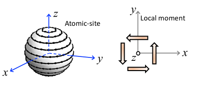
We point out that each of the ME multipoles in Eqs. (6)-(8) can be further decomposed into two contributions, one originating from the magnetization density asymmetry around an atomic site (known as the atomic site () contribution) and one from the asymmetric distribution of the local dipole moments (called the local moment (loc) contribution) Spaldin et al. (2013). The two contributions are illustrated schematically for the case of the component of the toroidal moment in Fig. 1. Mathematically, the decomposition for the toroidal moment is given by, Ederer and Spaldin (2007)
| (9) | |||||
where the summation is over all the atoms that have a local magnetic moment.
II.2 Anti-symmetric Compton profile
Next we show that all the ME multipoles described above contribute to the anti-symmetric Compton profile, and identify the correspondence between each specific ME multipole and the antisymmetric Compton profile along a particular direction in momentum space.
Compton scattering is an inelastic X-ray scattering process in which the energy loss of the photon is proportional to the projection of the electron momentum density along the direction of the photon momentum transfer. As a result, the measured double differential cross-section along direction say, is linearly proportional to the Compton scattering profile, , which is related to the electron momentum density, , by:
| (10) |
In materials, where either of the two symmetries, space-inversion and time-reversal, is present or both , and the Compton scattering profile is symmetric in momentum. If both symmetries are broken, however, neither the electron momentum density nor the Compton profile are required to be symmetric with respect to . This was pointed out in Ref. Collins et al. (2016), where it was suggested that Compton scattering could therefore be used to probe the toroidal moment . Here we extend Ref. Collins et al. (2016), to show that not only the toroidal moments but also all the other ME multipoles can have an antisymmetric contribution to their Compton scattering.
Next we connect the Compton profile to the momentum space representation of the ME multipoles via the multipole expansion of the density matrix. The parity-odd and time-odd sector of the density matrix is of interest to us, as it corresponds to the anti-symmetric part of the Compton profile.
Therefore, we expand the density matrix , with respect to its behavior under space inversion and time reversal,
| (11) |
Expanding the part of the density matrix that is odd under both space and time inversion, , in terms of the ME multipoles in Eqs. 6-8, we obtain Spaldin et al. (2013)
| (12) |
Here represents the rank of the parity odd () and time odd () ME multipoles, discussed in section II.1, with corresponding to the ME monopole, toroidal moment, and the quadrupole moment respectively, and the integer runs from . Since describes the component of the density that is odd under both time-reversal and space-inversion, we can conclude that all ME multipoles contribute to the anti-symmetric Compton profile.
Next we analyze the momentum space representations of the time-odd, parity-odd multipoles, in order to establish the directions in which the anti-symmetric Compton profile is non-zero. The momentum space representations of the odd-parity multipoles have a different form from their real space representations due to the nontrivial duality between the real space and the momentum space. We can see this from the following considerations: The functional form of the spatial part of the odd parity multipoles must be odd order in both and space, because both and change sign under inversion i.e. , and . Under time-reversal, however, the behavior of and is different, with , but . As a result, the spin dependence must be different in the real-space and the momentum space representations. This leads to the following intriguing consequences for the odd parity multipoles: First, the basis functions of the odd-parity magnetic multipoles in momentum space are spin-independent but odd order in . This gives rise to antisymmetric electron (and magnon) dispersions Watanabe and Yanase (2017, 2018) which manifest as the anti-symmetric Compton profile. Second, the specific basis function of the allowed ME multipole in a system dictates the momentum direction of the anti-symmetric Compton profile. The detection of the anti-symmetric Compton profile along a certain direction, therefore, can be used to identify the presence of a particular ME multipole in a material.
III Anti-symmetric Compton profile in example systems:
In order to illustrate the above ideas of the anti-symmetric Compton profile, we explicitly compute and analyze the Compton profile, for two example materials (i) LiNiPO4 and (ii) Mn2Au. While LiNiPO4 is an insulating system and exhibits the linear ME effect Mercier and Bauer (1968), Mn2Au is an anti-ferromagnetic metal, in which an electric current has been shown to reorient the direction of the magnetization Shick et al. (2010); Bodnar et al. (2018); Chen et al. (2019); Thöle et al. (2020). The presence of ME multipoles has been demonstrated computationally for both materials, and their relevance for the electric-field or electric-current induced magnetism discussed Spaldin et al. (2013); Thöle et al. (2020). Here, using a combination of symmetry analysis and DFT calculations, we show that the anti-symmetric Compton profile acts as a unique fingerprint of the symmetry-allowed ME multipoles in these materials. From a detailed analysis of the DFT results, we extract the role of the magnetic structure, band structure and SOC effects in the anti-symmetric Compton scattering. The insight into the physical mechanism that these provide is a first step to identifying materials with a larger anti-symmetric Compton response.
III.1 Insulating system:
LiNiPO4 crystallizes in the olivine structure with the orthorhombic space group and the crystallographic point group Abrahams and Easson (1993). The crystal structure, in which the Ni atoms at Wyckoff positions are surrounded by six oxygen atoms forming distorted NiO6 octahedra, is shown in Fig. 2(a). The material undergoes various magnetic transitions in the presence of a magnetic field, and the resulting phases exhibit linear and quadratic ME effects Fogh et al. (2020). Out of these various magnetic phases, the magnetic structure corresponding to the magnetic space group with the propagation vector constitutes the magnetic ground state of the system. In this magnetic structure, the Ni atoms are anti-ferromagnetically ordered, with the major spin component along the direction and a small component due to canting [see Fig. 2 (a)]. The magnetic configuration breaks the inversion symmetry of the structure, allowing for ME toroidal and quadrupole moments consistent with its off-diagonal linear ME effect Jensen et al. (2009); Spaldin et al. (2013); Fogh et al. (2020). Here, we discuss the manifestation of these allowed ME multipoles in the anti-symmetric Compton profile of LiNiPO4.
III.1.1 Symmetry analysis
| IR | ME multipole | Basis in | |
|---|---|---|---|
| Real space | space | ||
| , | |||
| , | , | ||
Before presenting the results of DFT calculations for the anti-symmetric Compton profile in LiNiPO4, we first analyze the symmetry of the magnetic structure and the allowed ME multipoles. This symmetry analysis reveals the direction(s) of the non-zero anti-symmetric Compton profile in momentum space, which we further verify in our DFT calculations presented in section III.1.2.
The real and momentum space basis functions for the time-odd, parity-odd ME multipoles, corresponding to the point group , of LiNiPO4, are obtained following Ref. Watanabe and Yanase (2018) and using the following compatibility relations Inui et al. (1990); Perez-Mato et al. (2015), the IRs of point group reduce to the point group as , , , , . and the result is listed in Table 1.
The magnetic ground state () of LiNiPO4 corresponds to the IR representation . As seen from Table 1, this representation allows for a net toroidal moment along the direction () and a quadrupole moment. The magnetic point group at the Ni site allows in addition for the atomic-site ME monopole and quadrupole moments , . These, however, are arranged in an anti-ferro type pattern between the Ni atoms, so that the net values of these ME multipoles are zero.
We now focus on the basis functions for these ME multipoles, which is crucial for the desired anti-symmetric Compton profile. As expected from the discussion of the real space-momentum space duality in section II.2, the real space basis functions in Table 1 are spin dependent while the momentum space basis functions are not. More interestingly, the basis functions in the momentum space are always odd order in . For example the momentum space basis for the ME multipoles (in the representation) is , indicating an asymmetric dispersion along direction. Thus, for LiNiPO4, we expect an anti-symmetric Compton profile along the -direction in momentum space, as well as along any directions with .
It is interesting to point out here that each of the ME multipoles in Table 1 allows for an antisymmetric Compton profile. For example, the existence of the ME multipoles and indicate an antisymmetric profile along (and any direction with ) and (and any direction with ) respectively. The situation is, however, different for the ME monopole moment and the quadrupole moments , which give rise to an antisymmetric profile only along the direction in the momentum space, where simultaneously conditions are satisfied (see Table 1). While these symmetry arguments are useful for predicting the directions in which an anti-symmetric Compton profile will occur, to develop an understanding of the process, and in particular to identify materials with large responses, it is instructive to know the magnitude of the anti-symmetric profile.
III.1.2 DFT results for the Compton profile
In order to verify the above symmetry analysis as well as to gain insight into the physics of the anti-symmetric Compton profile, we next compute the anti-symmetric Compton profile for LiNiPO4 using the linearized augmented plane wave (LAPW) method as implemented in the ELK code cod ; Ernsting et al. (2014). We use the LDA+SOC+ formalism, with eV and eV at the Ni site, except in the cases for which we study the effects of varying these parameters. A basis set of , a k-point sampling of the Brillouin Zone are used to achieve self-consistency. The product of the muffin-tin radius (2.0, 2.4, 2.2, and 1.8 a.u. for Li, Ni, P, and O respectively) and the maximum reciprocal lattice vector is taken to be 7. All calculations are done at the relaxed atomic positions and lattice constants reported in Ref. Spaldin et al. (2013). The electron momentum densities are calculated and projected onto the selected momentum directions () to obtain the Compton profile Ernsting et al. (2014). The computed profile is, further, separated into symmetric and anti-symmetric parts, using . The convergence of the symmetric and the anti-symmetric parts of the profile are confirmed by performing additional calculations with the denser k-point mesh. The computed symmetric and anti-symmetric parts of the profiles are normalized to the number of valence electrons per formula unit of LiNiPO4 in the calculation, which is 48 electrons. The isotropic core contribution, obtained from the Hartree-Fock calculations of Biggs et. al. Biggs et al. (1975), is further added to the symmetric part of the profile to obtain the total Compton profile.
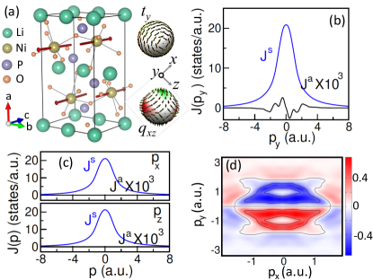
Our computed Compton profiles for the magnetic ground state along the crystallographic , and directions [Figs. 2 (b) and (c)] show that the anti-symmetric part is only non-zero along the direction in momentum space, consistent with the symmetry analysis. The symmetric and the anti-symmetric parts of the profile along are shown in Fig. 2 (b). As seen from this figure, both and satisfy the zero-sum rule . While this sum rule is trivial for the symmetric part, it imposes rather a stringent constraint on each half of the antisymmetric profile, that is Collins et al. (2016). This condition indicates that for each half of , a positive contribution is always accompanied by a negative contribution, and vice versa, which can also be verified visually from Fig. 2 (b). Note that the computed anti-symmetric part is rather small in magnitude, at least three orders of magnitude smaller than that of . The anti-symmetric part of the line integral of the electron momentum density in the plane is shown in Fig. 2 (d), where it is evident that this quantity is anti-symmetric along .
The obtained anti-symmetric Compton profile can be related to the details of the band structure as follows: The presence or absence of and symmetries dictate the symmetry conditions on the band energies for any arbitrary momentum point and the corresponding , with , while . The combination of both and symmetries consequently leads to doubly degenerate bands at every momentum point in the BZ, . In the present case, individual and symmetries are broken but the combined symmetry is preserved. In this case, all bands remain doubly degenerate everywhere in the BZ due to the symmetry, however, there is no symmetry restriction, as the individual and symmetries are broken, that guarantees that bands at and have the same energies. This leads to an asymmetric band structure in momentum space.
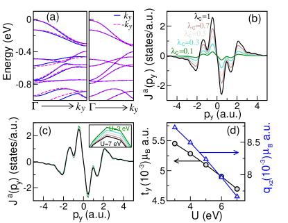
The direction of the asymmetric band structure is determined by the momentum space basis function of the specific parity-odd, time-odd multipoles, present in the system. In the case of LiNiPO4, the ME multipoles and give rise to an asymmetric band structure along , as shown in Fig. 3 (a) (left). This asymmetric band structure, further, leads to the asymmetric Compton profile. Therefore, the asymmetry in the Compton profile, determined by the anti-symmetric part , is a measure of the parity-odd, time-odd ME multipoles.
It is important to point out, here, that the SOC is absolutely essential to create such an asymmetric band structure, and, hence, the asymmetric Compton profile. This is because the asymmetric magnetization density due to broken and symmetries, which is represented by the ME multipoles, can only couple to the space via SOC. In the absence of SOC, such coupling is absent and the band structure remains symmetric as shown in Fig. 3 (a) (right). Since the anti-symmetric Compton profile is a manifestation of such an asymmetric band structure, it in turn also occurs only in presence of the SOC. In fact, the magnitude of has a strong dependence on the strength of the SOC, as we can see by artificially changing the SOC value in LiNiPO4. As depicted in Fig. 3 (b), with decreasing the strength of the SOC constant, we find that the anti-symmetric Compton profile decreases substantially as we decrease the strength of the SOC constant, .
On the other hand, the dependence of on the value of the Coulomb interaction parameter is quite weak, with the height of the peak in decreasing only slightly with increasing [see Fig. 3 (c)]. The weak dependence may be attributed to the slight decrease in the computed value of the ME multipoles , and as increases, shown in Fig. 3 (d), indicating that the size of the anti-symmetric Compton profile depends on the size of the ME multipoles. We discuss this next.
III.1.3 Role of ME multipoles: Effect of manipulation of the magnetic structure
To understand the role of the ME multipoles in the Compton profile, we next explicitly compute the symmetry-allowed atomic-site ME multipoles on the Ni ions. In order to compute the atomic-site contributions, the density matrix is decomposed into tensor moments, of which the parity-odd tensor moments have contributions only from the odd terms Spaldin et al. (2013). We therefore evaluate both the and matrix element contributions. In particular, we manipulate the local magnetic dipolar order of the system, to cause either a change in the magnitude of the multipoles or to give rise to an entirely new set of ME multipoles. We then calculate the corresponding changes in the anti-symmetric Compton profile.
In the magnetic ground state of LiNiPO4, the spin moments are primarily oriented along the direction () with a small canting angle , that gives rise to a tiny component of moment () as well Jensen et al. (2009). We investigate the effect of changing this canting angle on both the ME multipoles as well as the Compton profile. While changing , the spins are always kept in the plane, and the magnetic symmetry of the structure is also kept preserved. Since this particular magnetic symmetry allows ferro-type ordering for only and , no additional ferro-type ME multipoles appear as a result of change in the canting angle, but the magnitude of these multipoles may vary with the change in . Indeed, with increase in the magnitude of the atomic site contributions to increases, while that of decreases, as shown in the inset of Fig. 4 (a).
Similar behavior is also seen in the local moment (loc) contributions to and , where the loc contribution to , , can be calculated using Eq. 9, and the quadrupole moment can be calculated similarly using . Here , denote the or cartesian coordinates of the Ni atom at site , and , are the corresponding cartesian components of the spin moments, as listed in Table 2. Performing straightforward algebra, we obtain the local moment contribution to ,
| (19) |
Here, and are the orthorhombic lattice constants, and are arbitrary integers, and is the magnitude of the Ni spin moment. It is easy to see that a non-trivial exists only along the direction, as it should according to symmetry, and this component increases with increasing . In contrast, the non-trivial decreases in magnitude as increases.

The corresponding changes in the anti-symmetric part of the Compton profile are depicted in Fig. 4 (a). We see that, with increase in , the height of the first peak (the peak at smaller ) in increases, whereas the second peak (the peak at larger ) decreases. Correlating this behavior with the simultaneous increase in and decrease in calculated above, suggests that the two peaks may be associated with the two different ME multipoles and respectively.
We can, further, manipulate the magnetic structure of LiNiPO4 by completely changing the spin configuration so that the symmetry changes from the actual magnetic ground state symmetry of . The introduction of new magnetic symmetries enables different ferro-type ordered ME multipoles, offering the possibility of studying the effects of ME multipoles other than and on the anti-symmetric Compton profile.
| Site() | ||||||
|---|---|---|---|---|---|---|
| Ni(1) | 0 | |||||
| Ni(2) | 0 | |||||
| Ni(3) | 0 | |||||
| Ni(4) | 0 |
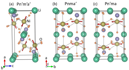
We made all three possible changes in the magnetic structure that are allowed by the structural symmetry of LiNiPO4 and also have a net ME multipole moment, while keeping the dimension of the magnetic unit cell the same as that of the structural unit cell. In the first case, we kept the Ni spin moments in the same plane, but changed their relative magnetic arrangement so that the components of Ni(1) and Ni(4) are parallel to each other and anti-parallel to those of Ni(2) and Ni(3), while the parallel components of Ni(1) and Ni(2) are anti-parallel to those of Ni(3) and Ni(4). This corresponds to the magnetic space group [see Fig. 5 (a)] and the IR representation in Table 1, which allows for a ME monopole and the quadrupole moments , with the momentum space basis function . In this case, the computed Compton profile has an anti-symmetric part only along the direction, as shown in Fig. 4 (b).
We can, further, rotate the spins in the out-of-plane direction, in such a way that they have only components. Among the various possibilities, only two arrangements support a net ME multipole moment and are allowed by symmetry. These two magnetic configurations are shown in Figs. 5 (b) and (c). In one of these two configurations, the parallel spin moments on Ni(1), Ni(4) are anti-parallel to those of Ni(2), Ni(3), and in the other configuration Ni(1) and Ni(2) have parallel spins, which are anti-parallel to those of Ni(3) and Ni(4). The former corresponds to the magnetic space group and the IR representation , while the later corresponds to the magnetic space group with the IR representation . Calculations for these two magnetic structures show the presence of anti-symmetric Compton profiles along and respectively [see Figs. 4 (c) and (d)], consistent with the momentum space basis functions for the allowed multipoles and respectively (see Table 1).
The above analysis of the manipulation of the magnetic structure provides two important conclusions. First, it confirms our argument that all the ME multipoles contribute to the anti-symmetric Compton profile and not just the toroidal moment, which is one of the central results of the present work. Secondly, it emphasizes the dependence of the anti-symmetric Compton profile on the fine details of the magnetic structure, suggesting that the manipulation of the spin configuration may also be used to decompose the profile into individual ME multipole moment contributions.
III.2 Metallic system:
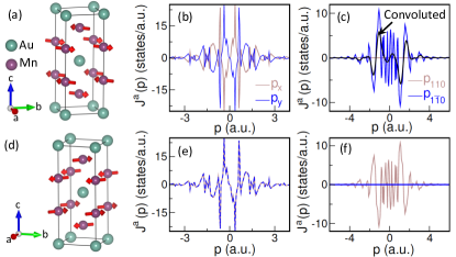
We now turn to our second example, Mn2Au, which crystallizes in the tetragonal structure () with point group symmetry Wells and Smith (1970). The material exhibits AFM ordering with the spins having easy plane anisotropy Bodnar et al. (2018). In contrast to the previously discussed LiNiPO4, Mn2Au is a good conductor. Interestingly, the electric current in Mn2Au induces a switching of the Néel vector, which can be used to write (store) or read-out information, making it a promising material for the present day hot topic of AFM spintronics Bodnar et al. (2018); Chen et al. (2019). The ground-state magnetic structure of Mn2Au, corresponding to the magnetic space group with Néel vector, is depicted in Fig. 6 (a). Similarly to LiNiPO4, the magnetic structure in Mn2Au breaks the inversion symmetry, allowing for ME toroidal and quadrupole moments leading to an off-diagonal tensor. The specific magnetic configuration of Mn2Au leads to interesting symmetry properties between the allowed ME multipoles, which, further, manifest in the asymmetric band structure as well as in the anti-symmetric Compton profile in Mn2Au. Below we discuss these symmetry relations in detail and point out the intriguing features of the band structure and the anti-symmetric profile in Mn2Au, which in addition to their relevance for Compton scattering might also be important for other experiments.
| IR | ME multipole | Basis in | |
|---|---|---|---|
| Real space | -space | ||
| , | |||
III.2.1 Symmetry analysis
The allowed ME multipoles and their real and momentum space basis functions in the different IR representations of the point group , relevant to Mn2Au, are listed in Table 3. The magnetic structure of Mn2Au belongs to the IR representation , which allows for toroidal moments along and directions, and , and also for quadrupole moments and . No additional local ME multipoles are allowed at the Mn site, forbidding any additional ME multipoles with anti-ferro type arrangement. It is interesting to point out here that the allowed multipole tensor for the magnetic ground state, corresponding to the magnetic space group , has the constraints , and . This, in turn, imposes an additional constraint on the allowed ME multipoles, that (see Eq. 4).
As expected, the momentum-space basis functions of the time-odd, parity-odd ME multipoles in Table 3 are always spin independent and odd order in . According to the momentum-space basis function for the allowed ME multipoles in Mn2Au, anti-symmetric Compton profiles should appear along and directions (see Table 3), which we, further, verify by explicitly computing the anti-symmetric Compton profile as discussed below.
III.2.2 DFT results for the Compton profile and ME multipoles
We compute the anti-symmetric Compton profile for Mn2Au using the ELK code cod ; Ernsting et al. (2014), following the same method as discussed in section III.1.2. All calculations are performed with the experimentally reported structure Wells and Smith (1970) within the LDA+SOC+ formalism with the correlation parameters eV and eV at the Mn site. The specific choice of the correlation parameters is guided by recent photoemission measurements Elmers et al. (2020), the results of which can be reproduced satisfactorily with these parameters. It is important to point out here that, in contrast to the insulating LiNiPO4, the anti-symmetric Compton profile in Mn2Au has a strong dependence on the choice of -point mesh, and the convergence of the anti-symmetric profile is achieved at a much higher -point grid of .
In the computed magnetic ground state, the magnetic moment at each Mn site projected onto ionic radius 2.4 a.u. is about 4.1 . In this magnetic structure, our calculations find that only the , , , and ME multipoles have non-zero values, and that they have ferro-type arrangements between different Mn atoms, as expected from the symmetry analysis. In addition, the computed components of the toroidal moment as well as the quadrupole moments are not independent but are related to each other by , and . These relations satisfy the symmetry imposed condition on the ME multipoles , as mentioned earlier.
Interestingly, for the Néel vector orientation, which is symmetry equivalent to the Néel vector but represents a different magnetoelectric domain Elmers et al. (2020); Sapozhnik et al. (2018), the relative signs of the toroidal and the quadrupole moment components switch, such that , and . These relative orientations of the computed multipoles can be understood directly from their formal definitions, given in section II. For example, according to the definition of the toroidal moment, and , which gives for and ( Néel vector), but for and ( Néel vector). Similarly, it is easy to show that and are the same in both sign and magnitude for orientation of the Néel vector, while they have opposite signs when the Néel vector is along . The computed magnitudes of the independent components of the allowed ME multipoles at the Mn site are a.u. and a.u., where we have added the and matrix element contributions to obtain the total atomic site contribution for each Mn atom. These ME multipoles lead to interesting consequences in the corresponding band structure and the anti-symmetric Compton profile as we now proceed to discuss.
The calculation of the Compton profile along the three Cartesian directions , , and shows an anti-symmetric component only along and , while is absent along , in agreement with the symmetry analysis, discussed earlier. As seen from Figs. 6 (b) and (c), unlike LiNiPO4, the anti-symmetric profile in Mn2Au has sharp peaks at lower momentum, which also change their signs rapidly. Also, the anti-symmetric profile has a larger magnitude compared to that in LiNiPO4, which may be attributed to the presence of the heavy Au atom leading to stronger SOC effects in Mn2Au.
It is interesting to point out here that the anti-symmetric parts along and directions are exactly equal and opposite to each other, i.e., [see Fig. 6 (b)]. This leads to a vanishing anti-symmetric Compton profile along the direction in momentum space, while a non-zero anti-symmetric profile appears in the perpendicular direction as shown in Fig. 6 (c). The convolution of the computed profile with an experimental resolution (Gaussian of FWHM) of 0.44 a.u. shows that while the sharp peaks as well as their oscillations in low momentum regime may be suppressed, some oscillating features can still be captured within this resolution limit [see Fig. 6 (c)].
Furthermore, switching of the Néel vector to the direction results in an exactly opposite situation, as depicted in Figs. 6 (e) and (f). In this case, the anti-symmetric profiles along and are equal in both magnitude and sign, leading to the presence of an anti-symmetric Compton profile along direction in momentum space, while it is absent along . This may be of importance to the experimental measurements, where an electric current-induced switching of the Néel vector, in turn, results in a switching of the anti-symmetric Compton profile from the to the direction in the momentum space.
These distinct features of the anti-symmetric Compton profile in Mn2Au may be understood from careful analysis of the corresponding band structures. The computed band structure for the magnetic ground state of Mn2Au with Néel vector shows that the bands are asymmetric along and directions [see Figs. 7 (a) and (b)]. The asymmetry of the bands in the presence of SOC follows from similar symmetry arguments to those discussed above for the case of LiNiPO4. Interestingly, the comparison of the bands along and shows that the band asymmetry is opposite for these two directions, explaining the opposite signs of the computed anti-symmetric profiles along and . The asymmetry of the bands is even more pronounced along the direction of the momentum space, while along the direction the bands are absolutely symmetric as depicted in Figs. 7 (c) and (d). This explains, further, the presence and the absence of the anti-symmetric Compton profile along the and directions respectively.
In contrast, switching of the magnetization direction to results in similar asymmetries along and directions as understood by comparing the bands shown in Figs. 7 (e) and (f). This results in a band asymmetry along the direction, while the bands remain symmetric in the perpendicular direction [see Figs. 7 (g) and (h)], consistent with the switching of the anti-symmetric Compton profile by changing the orientation of the Néel vector in Mn2Au. Interestingly, changes in the energy of the conduction electrons corresponding to the different Néel vectors are also recently reported in the photo-emission measurements on Mn2Au thin films Elmers et al. (2020). (Note that the unit cell of the reported thin film in Ref. Elmers et al., 2020 is rotated with respect to the bulk unit cell considered in our calculation, and our and directions correspond to their , directions respectively.) The confirmation of left-right asymmetry in the band structure is, however, not possible from these measurements as the photo-emission intensity from the two domains was averaged out Elmers et al. (2020).
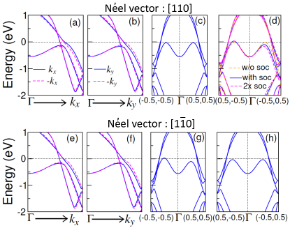
Similarly to the case of LiNiPO4, these asymmetries in the band structure can be traced back to the allowed ME multipoles in momentum space (see Table 3). Physically speaking, the spin asymmetry, designated by the allowed ME multipoles, couples to the momentum space via SOC, resulting in a band asymmetry. This is further evidenced by comparing the band structures for two different values of SOC, as shown in Fig. 7 (d), where we see that doubling the strength of the SOC results in an enhanced asymmetry.
Finally, we want to emphasize the one-to-one correspondence between the band asymmetries along or directions in the momentum space for the two Néel vectors and in Mn2Au and the respective directions of the allowed toroidal moment vectors or . We note that the components of the quadrupole moment tensors have also the same symmetry as the allowed toroidal moment, belonging to the same irreducible representation. It is interesting to point out that the same ME multipoles can provide a convenient description of the current induced switching of the Néel vectors in Mn2Au Thöle et al. (2020). Our theoretical analysis suggests a presence of band asymmetry in Mn2Au and its switching with the change in Néel vector, that are signatures of the allowed ME multipole moments in the system.
IV Summary and outlook
In summary, we have presented a comprehensive theoretical analysis of the anti-symmetric Compton profile in materials with non-centrosymmetric magnetic ordering. We have shown that the anti-symmetric Compton profile is a signature of parity-odd, time-odd ME multipoles. The ME multipoles, which break both space-inversion and time-reversal symmetries, generate an asymmetry in the magnetization density, the details of which are governed by the specific components of the ME multipoles that occur. The asymmetry, in turn, can be characterized by the basis functions of the corresponding ME multipoles, which, since the ME multipoles are odd parity, are different in real and momentum space. In particular, while the real space basis functions for ME multipoles are always spin dependent, the momentum space basis functions are not. As a result, they can be probed in -space without any spin-resolved measurements. In addition, since the momentum-space bases for ME multipoles are always odd order in , they generate asymmetry in the electronic band dispersion in momentum space, with the direction of asymmetry determined by the specific momentum-space basis. Since the Compton scattering is a measure of the electron-momentum density, an asymmetry in the Compton scattering profile is generated in the presence of ME multipoles. The coupling of the magnetization asymmetry to the space requires the presence of SOC, indicating the importance of SOC effects in generating the anti-symmetric Compton profile.
In addition to emphasizing the role of the real space-momentum space duality in understanding the anti-symmetric profile, our work points out the two essential ingredients for an anti-symmetric Compton profile: time-odd, parity-odd ME multipoles and SOC. This can in turn be used to guide the search for suitable candidate materials with larger anti-symmetric Compton profiles. We note that earlier attempts were not inconsistent with the theoretical predictions, but were not conclusive as the observed anti-symmetric signal fell within the statistical error Collins et al. (2016); Collins . The ME multipoles requirement means that the anti-symmetric profile has a strong dependence on the magnetic structure of the system. This leads to the possibility of tuning the profile by manipulating the magnetic structure, as discussed in section III.1.3. The SOC requirement suggests a route to identifying materials with a stronger effect by choosing materials with heavy elements, and therefore strong SOC. Furthermore, the finding of the current work that the anti-symmetric Compton profile is present for all ME materials, and not just those with ME toroidal moment, also broadens the scope for candidate materials.
Finally, our theoretical studies on the representative insulating and metallic candidate materials indicate some distinct features in the corresponding anti-symmetric Compton profiles. While the anti-symmetric profile has broad peaks in insulating LiNiPO4, the peaks are rather sharp and oscillating, specially in the low momentum regime, for the metallic system Mn2Au. We also predict some detailed features that should be experimentally observable, for example opposite changes in the two peak heights in LiNiPO4 as the spin canting angle is varied, and may give further insight into the detailed role of the ME multipoles. Of particular interest is the anti-symmetric Compton profile in Mn2Au, the direction of which can be switched between and by changing the orientation of the Mn spin moments from to . We hope that our predictions will stimulate more experiments in this direction.
Acknowledgements
The authors thank Stephen Collins, Jon Duffy, Michael Fechner, and Urs Staub for stimulating discussions. This work was supported by the European Research Council (ERC) under the European Union’s Horizon 2020 research and innovation programme project HERO grant agreement No. 810451. Computational resources were provided by ETH Zürich (Euler cluster).
References
- Landau and Lifshitz (1980) L. D. Landau and E. M. Lifshitz, The Classical Theory of Fields (Butterworth-Heinemann, Oxford (4th ed), 1980).
- Jackson (1999) J. D. Jackson, Classical Electrodynamics (Wiley, New York (3rd ed.), 1999).
- Blin-Stoyle (1956) R. J. Blin-Stoyle, Rev. Mod. Phys. 28, 75 (1956).
- Raab and Lange (2004) R. E. Raab and O. L. D. Lange, Multipole Theory in Electromagnetism: Classical, Quantum, and Symmetry Aspects, with Applications (Oxford University Press, Oxford, U.K., 2004).
- Kaelberer et al. (2010) T. Kaelberer, V. A. Fedotov, N. Papasimakis, D. P. Tsai, and N. I. Zheludev, Science 330, 1510 (2010).
- Spaldin et al. (2008) N. A. Spaldin, M. Fiebig, and M. Mostovoy, Journal of Physics: Condensed Matter 20, 434203 (2008).
- Hayami et al. (2018) S. Hayami, M. Yatsushiro, Y. Yanagi, and H. Kusunose, Phys. Rev. B 98, 165110 (2018).
- Spaldin et al. (2013) N. A. Spaldin, M. Fechner, E. Bousquet, A. Balatsky, and L. Nordström, Phys. Rev. B 88, 094429 (2013).
- Watanabe and Yanase (2020) H. Watanabe and Y. Yanase, Phys. Rev. Research 2, 043081 (2020).
- Dubovik and Tugushev (1990) V. Dubovik and V. Tugushev, Physics Reports 187, 145 (1990).
- Onimaru et al. (2011) T. Onimaru, K. T. Matsumoto, Y. F. Inoue, K. Umeo, T. Sakakibara, Y. Karaki, M. Kubota, and T. Takabatake, Phys. Rev. Lett. 106, 177001 (2011).
- Cricchio et al. (2009) F. Cricchio, F. Bultmark, O. Grånäs, and L. Nordström, Phys. Rev. Lett. 103, 107202 (2009).
- Santini et al. (2009) P. Santini, S. Carretta, G. Amoretti, R. Caciuffo, N. Magnani, and G. H. Lander, Rev. Mod. Phys. 81, 807 (2009).
- Sumita et al. (2017) S. Sumita, T. Nomoto, and Y. Yanase, Phys. Rev. Lett. 119, 027001 (2017).
- Watanabe and Yanase (2017) H. Watanabe and Y. Yanase, Phys. Rev. B 96, 064432 (2017).
- Fu (2015) L. Fu, Phys. Rev. Lett. 115, 026401 (2015).
- Staub et al. (2009) U. Staub, Y. Bodenthin, C. Piamonteze, M. García-Fernández, V. Scagnoli, M. Garganourakis, S. Koohpayeh, D. Fort, and S. W. Lovesey, Phys. Rev. B 80, 140410 (2009).
- Kimura et al. (2020) K. Kimura, T. Katsuyoshi, Y. Sawada, S. Kimura, and T. Kimura, Communications Materials 1, 39 (2020).
- Lovesey (2014) S. W. Lovesey, Journal of Physics: Condensed Matter 26, 356001 (2014).
- Lovesey et al. (2019) S. W. Lovesey, T. Chatterji, A. Stunault, D. D. Khalyavin, and G. van der Laan, Phys. Rev. Lett. 122, 047203 (2019).
- Collins et al. (2016) S. P. Collins, D. Laundy, T. Connolley, G. van der Laan, F. Fabrizi, O. Janssen, M. J. Cooper, H. Ebert, and S. Mankovsky, Acta Crystallographica Section A 72, 197 (2016).
- (22) S. P. Collins, “Anti-symmetric Compton scattering in LiNiPO4: Towards a direct probe of the magneto-electric multipole moment,” (to be submitted) 2021.
- Ederer and Spaldin (2007) C. Ederer and N. A. Spaldin, Phys. Rev. B 76, 214404 (2007).
- Watanabe and Yanase (2018) H. Watanabe and Y. Yanase, Phys. Rev. B 98, 245129 (2018).
- Mercier and Bauer (1968) M. Mercier and P. Bauer, C. R. Acad. Sci. Paris 267, 465 (1968).
- Shick et al. (2010) A. B. Shick, S. Khmelevskyi, O. N. Mryasov, J. Wunderlich, and T. Jungwirth, Phys. Rev. B 81, 212409 (2010).
- Bodnar et al. (2018) S. Y. Bodnar, L. Šmejkal, I. Turek, T. Jungwirth, O. Gomonay, J. Sinova, A. A. Sapozhnik, H. J. Elmers, M. Kläui, and M. Jourdan, Nature Communications 9, 348 (2018).
- Chen et al. (2019) X. Chen, X. Zhou, R. Cheng, C. Song, J. Zhang, Y. Wu, Y. Ba, H. Li, Y. Sun, Y. You, Y. Zhao, and F. Pan, Nature Materials 18, 931 (2019).
- Thöle et al. (2020) F. Thöle, A. Keliri, and N. A. Spaldin, Journal of Applied Physics 127, 213905 (2020), https://doi.org/10.1063/5.0006071 .
- Abrahams and Easson (1993) I. Abrahams and K. S. Easson, Acta Crystallographica Section C 49, 925 (1993).
- Fogh et al. (2020) E. Fogh, T. Kihara, R. Toft-Petersen, M. Bartkowiak, Y. Narumi, O. Prokhnenko, A. Miyake, M. Tokunaga, K. Oikawa, M. K. Sørensen, J. C. Dyrnum, H. Grimmer, H. Nojiri, and N. B. Christensen, Phys. Rev. B 101, 024403 (2020).
- Jensen et al. (2009) T. B. S. Jensen, N. B. Christensen, M. Kenzelmann, H. M. Rønnow, C. Niedermayer, N. H. Andersen, K. Lefmann, J. Schefer, M. v. Zimmermann, J. Li, J. L. Zarestky, and D. Vaknin, Phys. Rev. B 79, 092412 (2009).
- Inui et al. (1990) T. Inui, Y. Tanabe, and Y. Onodera, Springer, Berlin 78 (1990).
- Perez-Mato et al. (2015) J. Perez-Mato, S. Gallego, E. Tasci, L. Elcoro, G. de la Flor, and M. Aroyo, Annual Review of Materials Research 45, 217 (2015), https://doi.org/10.1146/annurev-matsci-070214-021008 .
- (35) “The Elk Code,” http://elk.sourceforge.net/.
- Ernsting et al. (2014) D. Ernsting, D. Billington, T. D. Haynes, T. E. Millichamp, J. W. Taylor, J. A. Duffy, S. R. Giblin, J. K. Dewhurst, and S. B. Dugdale, Journal of Physics: Condensed Matter 26, 495501 (2014).
- Biggs et al. (1975) F. Biggs, L. Mendelsohn, and J. Mann, Atomic Data and Nuclear Data Tables 16, 201 (1975).
- Wells and Smith (1970) P. Wells and J. H. Smith, Acta Crystallographica Section A 26, 379 (1970).
- Elmers et al. (2020) H. J. Elmers, S. V. Chernov, S. W. D’Souza, S. P. Bommanaboyena, S. Y. Bodnar, K. Medjanik, S. Babenkov, O. Fedchenko, D. Vasilyev, S. Y. Agustsson, C. Schlueter, A. Gloskovskii, Y. Matveyev, V. N. Strocov, Y. Skourski, L. Šmejkal, J. Sinova, J. Minár, M. Kläui, G. Schönhense, and M. Jourdan, ACS Nano, ACS Nano 14, 17554 (2020).
- Sapozhnik et al. (2018) A. A. Sapozhnik, M. Filianina, S. Y. Bodnar, A. Lamirand, M.-A. Mawass, Y. Skourski, H.-J. Elmers, H. Zabel, M. Kläui, and M. Jourdan, Phys. Rev. B 97, 134429 (2018).