∎
e1e-mail: nicola.casali@roma1.infn.it
Final results of CALDER: Kinetic inductance light detectors to search for rare events
Abstract
The next generation of bolometric experiments searching for rave events, in particular for the neutrino-less double beta decay, needs fast, high-sensitivity and easy-to-scale cryogenic light detectors. The CALDER project (2014-2020) developed a new technology for light detection at cryogenic temperature. In this paper we describe the achievements and the final prototype of this project, consisting of a cm2, 650 m thick silicon substrate coupled to a single kinetic inductance detector made of a three-layer aluminum-titanium-aluminum. The baseline energy resolution is 341(stat)2(syst) eV RMS and the response time is 120 s. These features, along with the natural multiplexing capability of kinetic inductance detectors, meet the requirements of future large-scale experiments.
Keywords:
Kinetic Inductance Detectors Double beta decay scintillation detector1 Introduction
More than 60 years after their first detection by Cowan and Reines Cowan:1992xc , the properties of neutrinos are still being investigated. Among them, the mass scale as well as their nature (Dirac or Majorana particle) are still unknown. If observed, a hypothesized nuclear process could unveil both of them: neutrino-less double beta decay (DBD) Furry ; Deppisch:2012nb . DBD is not allowed by the Standard Model since it violates the conservation of the B-L number Vissani:2016 . In this transition a nucleus decays emitting two electrons and no neutrinos, (A,Z)(A,Z+2)+2e-, and the signal would consist of two electrons with a total kinetic energy equal to the Q-value of the transition. Current upper limits on the half-life of the decay are of the order of yr, depending on the isotope under study agostini2020 ; PhysRevLett.117.082503 ; PhysRevC.100.025501 ; PhysRevLett.123.161802 ; PhysRevD.92.072011 ; PhysRevLett.123.032501 ; Adams:2019jhp ; Armengaud:2020:cupidmo .
Cryogenic calorimeters, hystorically also called “bolo-meters”, are among the leading technologies used to search for DBD. The most sensitive experiment based on this technique, CUORE Artusa:2014lgv , is operating 988 TeO2 cryogenic calorimeters of 750 g each with an average energy resolution of keV and a background index of counts/(keV kg yr) in the energy region of interest cuore2021 . These performances allowed the CUORE experiment to set a 90% C.I. Bayesian lower limit of yr on the 130Te half-life for DBD. The CUPID (CUORE Upgrade with Particle Identification) collaboration CUPIDInterestGroup:2019inu proposed a next generation DBD experiment to upgrade the technique of CUORE, with the goal of decreasing the background by two orders of magnitude. CUPID will implement an active particle identification technique in order to identify and reject the dominant background source, i.e. particles emitted by residual radioactive contamination in the materials facing the detectors Alduino:2017qet .
In the first design, CUPID was based on TeO2 cryogenic calorimeters, as in CUORE, complemented by cryogenic light detectors to detect the tiny amount of Cherenkov light (100 eV) emitted only by interactions Casali:2016luq , thus enabling the background rejection. Nevertheless, the results obtained by CUPID-0 PhysRevLett.123.032501 ; Azzolini:2018tum ; PhysRevLett.123.262501 ; Azzolini_excited_states ; Azzolini_Zn_decay ; PhysRevD.100.092002 and CUPID-Mo Armengaud:2020:cupidmo ; Armengaud:2019loe experiments demonstrated that the particles rejection capability can be more easily achieved by using scintillating crystals like ZnSe (DBD of 82Se) and Li2MoO4 (DBD of 100Mo) in place of the TeO2 ones because of their higher light signal compared with the Cherenkov yield. Furthermore 82Se and 100Mo benefit of a lower intrinsic background with respect to 130Te because their DBD Q-value is above 2615 keV, where the background contribution coming from natural radioactivity is greatly reduced. The CUPID group therefore decided to replace TeO2 crystals in favour of ZnSe or Li2MoO4. Finally, because of the better radio-purity and energy resolution with respect to ZnSe, Li2MoO4 was chosen as crystal for CUPID.
It is clear from the previous considerations that the light detection technology will play a key role in the future of CUPID. To reach the background goal of counts/ (keV kg yr), light detectors with small baseline fluctuations ( eV RMS), good time resolution (better than ms) and high reproducibility are needed. The light detectors of the first phase of the project will be based on the well established technology of germanium wafers equipped with Neutron Transmutation Doped Germanium (NTD-Ge) thermistors Beeman:2013zva . These sensors offer a typical baseline resolution of 50–60 eV RMS with rise time of 1–5 ms (see, e.g., Refs.Armengaud:2019loe ; Artusa_2016 ; Ressa_2021 and references therein). A detector of 16 cm2 in an optimized configuration reached an ultimate resolution of 20 eV RMS with rise time of 0.8 ms Barucci:2019ghi .
Nevertheless, the physics reach of CUPID (or other bolometric projects such as AMoRE Alenkov:2019jis ), could be largely increased with faster light detectors. Rise times of the order of hundreds of s or below would allow to reject the ultimate envisioned background, consisting of pile-up events from the naturally occurring double- decay with the emission of 2 neutrinos CUPIDInterestGroup:2020rna ; Chernyak2017 . Furthermore, detectors offering multiplexing capabilities would allow to increase the number of devices without increasing the thermal load on the cryogenic facility, and ease of fabrication and low-cost readout are highly desirable features for large scale experiments. Apart from the limited time resolution, NTD sensors, being high-impedance devices, cannot be easily multiplexed at cryogenic temperatures.
Light detectors based on transition edge sensors (TES) have also been proposed as an alternative to NTDs for rare events searches Schaffner:2014caa and demonstrated an extraordinary energy resolution down to 3.9 eV RMS with a distributed network of sensors Fink . Nevertheless, these devices cannot be easily scaled to thousands of channels because of their complex readout (based on SQUIDs) and limited reproducibility.
In this work we summarize the R&D and present the final results of the CALDER project, which developed an alternative technology to NTDs and TESs for the light detection based on Kinetic Inductance Detectors.
2 Kinetic Inductance Detectors with phonon mediation
In 2003 a new technology was proposed for the detection of electromagnetic radiation at cryogenic temperatures: the Kinetic Inductance Detectors (KIDs) bay . A KID consist of a resonant LC circuit made of a superconducting metal operated well below its critical temperature (see the layout of the KID of CALDER in Fig. 1 left). The inductance is the sum of the magnetic inductance (), which depends on the geometry of the inductor, and of the so called kinetic inductance (), which depends on the density of Cooper pairs in the superconductor.
For common superconductors such as aluminum, the binding energy of the Cooper pairs is of the order of hundreds of eV, so that even a tiny amount of absorbed energy can break a high number of Cooper pairs. The pair-breaking causes an increase of and of the surface resistance of the superconductor, , resulting in a measurable change of the frequency () and the quality factor () of the resonator (Fig. 1 right).
What makes KIDs interesting with respect to other cryogenic sensors is their natural multiplexing in the frequency domain. Indeed, hundreds of KIDs can be coupled to the same feedline, and can be simultaneously read by making them resonate at slightly different frequencies, which can be obtained by adjusting the layout of the capacitor and/or of the inductor of the circuit Mazin:2010pz . This allowed to successfully operate very large arrays of KIDs, up to 1000 Adam:2017gba . Despite these outstanding performances, their application in other fields could be limited by their small active surface (few mm2). However, Swenson et al. Swenson:2010 and Moore et al. Moore:2012 showed that KIDs are also good phonon sensors: X-rays or, more in general, ionising radiation interacting in a substrate generate phonons that, through their scattering in the lattice, can eventually reach the KIDs, break the Cooper pairs and generate a signal. With the mediation of the phonons in the substrate it is therefore possible to increase the sensitive area beyond the KID dimensions, at the cost of a lower sensitivity due to inefficiencies in phonon transmission and absorption in the KID.
3 The 4 and 25 cm2 light detectors of CALDER
The CALDER (Cryogenic wide-Area Light Detectors with Excellent Resolution) project Battistelli:2015vha developed large area cryogenic light detectors based on KIDs exploiting the phonon-mediation. The first prototypes Colantoni177:2016 ; Colantoni131:2016 were made depositing 4 multiplexed aluminum resonators on a cm2, 300 m thick silicon substrate (Fig. 2 left) and reached an energy resolution of 150 eV RMS Cardani:2015tqa . Then we improved the layout of the LC circuit in order to increase its area for a better phonon collection (from 2.4 to 4 mm2) and in order to increase the quality factor of the resonator (from 15000 to 150000), which in turn needed also an improvement of the quality and accuracy of the metal deposition Colantoni726:2018 . Good results were obtained, both in terms of energy resolution and rise time (80 eV and 10 s respectively) and also in wide range of operating temperatures ( mK) Bellini:2016lgg . A similar prototype was successfully used as cryogenic light detector coupled to a cm3 Li2MoO4, demonstrating very promising performances Casali:2019baq .
In order to further improve the energy resolution, we moved the R&D to KIDs made of superconductors more sensitive than aluminum. Indeed, the sensitivity depends strongly on that in turn depends on the material zmu . At the same time the superconducting material needs to feature a good acoustic match to the silicon, to ensure an efficient phonon transmission and absorption in the KID. We started testing several resonators made of sub-stoichiometric titanium nitride without obtaining satisfactory results, mainly because of the poor reproducibility of the film, a difficulty encountered also by other groups Leduc:2010 ; Szypryt:2017 . We then moved to granular aluminum that, because of its tunable energy gap and large fraction of kinetic inductance, is a promising material in applications for quantum circuits Gruenhaupt2019 . Nevertheless, we were not able to reach a baseline resolution better than 150 eV, likely because of the acustic mismatch between granular aluminum and silicon, that prevents an efficient collection of phonons.
On the contrary, multi-layers of aluminum and titanium showed from the beginning very promising results, thanks to the higher kinetic inductance of titanium. We tested several bi-layers consisting of titanium and aluminum with variable thickness. The best baseline resolution, 50 eV RMS, was obtained with 10 nm of titanium and 25 nm of aluminum. A further improvement was achieved moving from a bi-layer to a tri-layer of aluminum-titanium-aluminum, in order to enhance the acoustic match between KID and silicon. The best performance was obtained with a three-layer (14 nm Al, 33 nm Ti, 30 nm Al) that, thanks to a 8 times higher kinetic inductance than aluminum, allowed a very competitive baseline energy resolution of 26 eV RMS cruciani2018 .
The last step of the project consisting in the scale-up of the Si substrate to the final size of cm2. Such dimensions were chosen at the beginning of the CALDER R&D activity to match the size of the faces of the TeO2 crystals of CUORE, in order to maximize the light collection efficiency Casali:2016luq . Scaling the substrate surface from 22 to 55 cm2, and at the same time preserving the baseline resolution, turned out to be the most complex technological challenge. Even if we used the same KID design tested in previous detectors, we had to build and test tens of different prototypes before obtaining a comparable quality factor of the resonator. The reason behind this problem turned out to be the CPW feed line. Indeed, in order to decrease the number of phonons absorbed by non sensitive Al regions its width was only 85 m. At the same time, in order to collect as many phonons as possible, we increased the number of KIDs from 1 to 4, with the feedline running through the whole substrate and being 6 times longer than in the cm2 detector. This caused impedance mismatches that reduced by more than an order of magnitude the quality factor. This effect was not visible in EM simulations and therefore we proceeded by trials and errors. In the end the simplest solution turned out also to be the most reliable and high-performing: we minimized the feedline length by making it straight from one side of the wafer to the opposite one (5 cm), and coupled to it a single KID. Figure 2 (right) shows the final detector held in a copper frame by PTFE washers consisting in a cm2, 650 m thick Si wafer monitored by an AlTiAl (14 nm, 33 nm, 30 nm) three-layer resonator with the same geometry showed in Fig 1 left.
4 Measurement set-up
The device was anchored to the coldest point of a dry 3He/4He dilution refrigerator111Oxford Instruments, Dry Dilution Refrigerator Triton 200. and cooled down to 20 mK. The outside vessel of the refrigerator was surrounded by a -metal cylinder shield in order to reduced the magnetic field at the sample location. Finally, to prevent that both the residual magnetic field inside the cryostat and the thermal radiation from the 600 mK stage spoiled the resonator quality factor, the detector holder was placed inside a shielding pot consisting in a three layers of Cryophy® copper and aluminum (Fig. 3).
An optical fiber of 600 m core diameter was placed on the top of the pot and illuminated the Si substrate from a distance of 13.6 cm. The opposite end of the fiber was connected to a 400 nm LED lamp located at room temperature outside the refrigerator. Given the numerical aperture of the fiber of 0.22 and the distance from the Si surface, photons illuminate the entire 5x5 cm2 surface, thus simulating the crystal scintillation light. A 55Fe X-ray source was faced to a corner of the Si substrate, on the opposite position with the respect to the KID and the feedline.
The resonator was excited and probed at the resonant frequency, GHz. The output signals were fed into a CITLF3 SiGe cryogenic low noise amplifier ampli installed at the 4 K stage of the cryostat, down-converted at room temperature using a superheterodyne electronics and then digitized at a sampling frequency of 500 kSPS Bourrion:2011gi . Time traces up to 12 ms long of the real (I) and imaginary (Q) parts of the transmission S21 were acquired with a software trigger. Finally the I and Q waveforms were converted into phase and amplitude variations relative to the center of the resonance loop cruciani2018 .
Figure 4 shows a signal produced by an energy deposition of 1.3 keV in the Si wafer, which is similar to the light signal expected from the DBD of 100Mo. The average rise time of the signals is 120 s, dominated by the phonon propagation in the substrate, while the decay time is 550 s, dominated by the recombination of the Cooper pairs Martinez:2018ezx . For the estimation of the signal amplitude, the phase and amplitude waveforms are combined with a bi-dimensional matched filter to maximize the signal to noise ratio Bellini:2016lgg .
5 Results
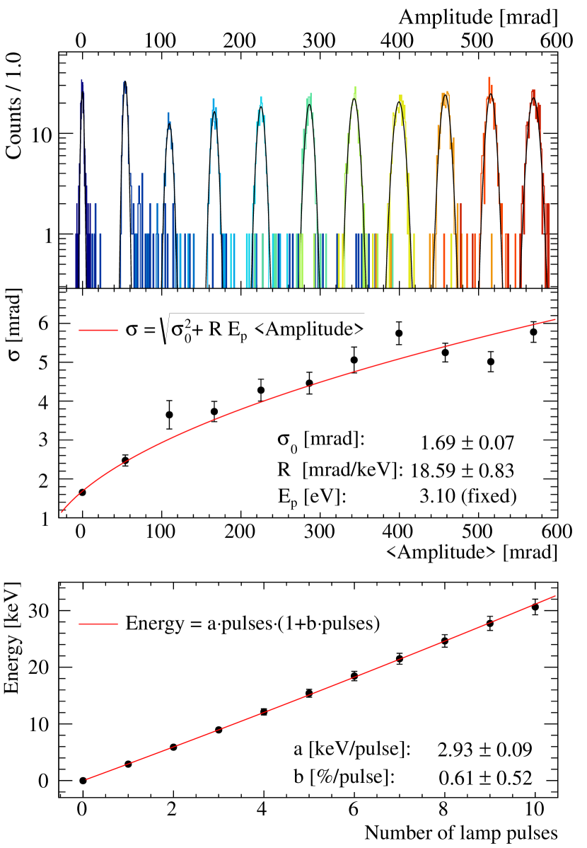
We used the LED lamp to shine different amount of photons and to perform an absolute energy calibration of the detector cruciani2018 . The lamp is controlled with an external trigger that we fire at increasing rate in order to increase the number of photons in a burst. The photon bursts are much shorter than the rise time of the signal, at maximum 2 s long, and are therefore seen as a from the KID. Each burst is composed by N photons of same energy (400 nm, corresponding to 3.1 eV) reaching the Si wafer and absorbed by it. We denote the average number of absorbed photons by . This process follows the Poisson statistics and therefore the standard deviation is .
As shown in Fig. 5 (top) for each optical burst, the distribution of the amplitude of the signals is well described by a Gaussian with a standard deviation . The predicted trend of as a function of the mean Amplitude () can be written as the combination of two uncorrelated terms that can be added quadratically, i.e. the poissonian component and the baseline noise energy resolution:
| (1) |
where is the baseline noise energy resolution, R the energy calibration coefficient and the photon energy. The vs trend is well described by Eq. 1 as shown in Fig. 5-middle and allowed us to extract the calibration coefficient mrad/keV. Finally, the bottom panel of the figure shows the calibrated energy as a function of the number of lamp triggers.
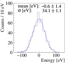
After calibration the baseline noise energy resolution is 90 eV, a value obtained with the pulse-tube cryocooler on and without any decoupling system to reduce vibrations (see e.g. Ref pirro ). These represent the least favorable configuration, since it is well known that the mechanical vibrations induced by dry refrigerators increase the noise of cryogenic detectors. NTDs and TES detectors, at least in the applications for rare events searches, cannot be even operated without a decoupling system. Indeed, the CUORE infrastructure implments a sophisticated system for the reduction of vibrations Nello ; cuorecryo and to emulate such “ideal” conditions we repeated the measurement with the pulse-tube off and obtained a baseline noise of eV (Fig. 6 left), where the systematic error arises from the calibration function.
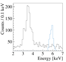
Figure 6 (right) shows the light-calibrated energy spectrum (black histogram) of the events produced by the 55Fe X-ray source. The reconstructed energy is significantly smaller the nominal one (6 keV), since these devices are sensitive to the position of the energy release Martinez:2018ezx and the source, unlike the fiber that illuminates uniformly the substrate, faces one corner of it far from the KID.
6 Conclusion
In this paper we described the technological challenges and solutions in the development of wide-area cryogenic light detectors based on Kinetic Inductance Detectors. We presented the final prototype of the CALDER project, a single KID made of a tri-layer aluminum-titanium-aluminum deposited on a 55 cm2 Silicon substrate acting as light absorber.
This light detector features a rise time of 120 s and a vibration-limited noise resolution of 90 eV RMS, matching the requirements of next-generation experiments. We proved that the energy resolution is not limited by the detector itself, rather by the vibrations induced by the pulse-tube cryocooler. In absence of such vibrations (e.g. in fridges such as the CUORE cryostat featuring an active noise cancellation or implementing a decoupling system for the pulse-tube) the energy resolution improve to 34 eV RMS.
Compared to the baseline technology of CUPID, the presented device has a similar energy resolution and an order of magnitude faster response time, a key parameter for background suppression. Finally, it offers ease in multiplexing and simple fabrication, important aspects for experiments with thousands of channels.
Acknowledgements.
This work was supported by the European Research Council (FP7/2007-2013) under Contract No. CALDER No. 335359 and by the Italian Ministry of Research under the FIRB Contract No. RBFR1269SL. The authors thank M. Calvo, M.G. Castellano, C. Cosmelli, A. Monfardini, H. Le Sueur and I.M. Pop for the precious collaboration and the useful discussions during the development of the project. The authors also thanks the personnel of INFN Sezione di Roma for the technical support, in particular M. Iannone, A. Girardi and S. Casani.References
- (1) C. Cowan, F. Reines, F. Harrison, H. Kruse and A. McGuire, Science 124 (1956), 103-104. DOI 10.1126/science.124.3212.103
- (2) W. H. Furry, Phys. Rev. Lett. 56, 1184 (1936).
- (3) F. Deppisch, M. Hirsch, and H. Ps, J. Phys. G 39, 124007 (2012). DOI 10.1088/0954-3899/39/12/124007.
- (4) F. Vissani et al., Adv. in High Energy Phys. 2016, 2162659, (2016). DOI 10.1155/2016/2162659.
- (5) The GERDA Collaboration, Phys. Rev. Lett. 125, 252502 (2020). DOI 10.1103/PhysRevLett.125.252502.
- (6) The KamLAND-Zen Collaboration, Phys. Rev. Lett. 117, 082503 (2016). DOI 10.1103/PhysRevLett.117.082503.
- (7) The Majorana Collaboration, Phys. Rev. C. 100, 025501 (2019). DOI 10.1103/PhysRevC.100.025501.
- (8) The EXO-200 Collaboration, Phys. Rev. Lett. 123, 161802 (2019). DOI 10.1103/PhysRevLett.123.161802.
- (9) The NEMO-3 Collaboration, Phys. Rev. D, 92, 072011 (2015). DOI 10.1103/PhysRevD.92.072011.
- (10) The CUPID-0 Collaboration, Phys. Rev. Lett. 123, 032501 (2019). DOI 10.1103/PhysRevLett.123.032501.
- (11) D. Q. Adams et al. [CUORE Collaboration], Phys. Rev. Lett. 124 no.12, 122501 (2020). DOI 10.1103/PhysRevLett.124.122501.
- (12) Phys. Rev. Lett. 2021 (in press).
- (13) D. R. Artusa, et al., Adv. High Energy Phys. 2015, 879871 (2015). DOI 10.1155/2015/879871
- (14) The CUORE Collaboration, “High sensitivity search for neutrinoless double beta decay in Te with one tonne-year of CUORE data”, in preparation.
- (15) W. R. Armstrong et al. [CUPID], “CUPID pre-CDR,” [arXiv:1907.09376 [physics.ins-det]].
- (16) C. Alduino et al. [CUORE Collaboration], Eur. Phys. J. C 77 no.8, 543 (2017). DOI 10.1140/epjc/s10052-017-5080-6.
- (17) N. Casali, Astropart. Phys. 91, 44 (2017), DOI 10.1016/j.astropartphys.2017.03.004.
- (18) O. Azzolini et al. [CUPID Collaboration], Eur. Phys. J. C 78 428 (2018). DOI 10.1140/epjc/s10052-018-5896-8
- (19) The CUPID-0 Collaboration, Phys. Rev. Lett. 123, 262501 (2019). DOI 10.1103/PhysRevLett.123.262501
- (20) The CUPID-0 Collaboration, Eur. Phys. J. C, 78, 888 (2018). DOI 10.1140/epjc/s10052-018-6340-9.
- (21) The CUPID-0 Collaboration, Eur. Phys. J. C, 80, 702 (2020). DOI 10.1140/epjc/s10052-020-8280-4.
- (22) The CUPID-0 Collaboration, Phys. Rev. D, 100, 092002 (2019). DOI 10.1103/PhysRevD.100.092002.
- (23) E. Armengaud et al., Eur. Phys. J. C 80 (2020) no.1, 44. DOI 10.1140/epjc/s10052-019-7578-6.
- (24) J.W. Beeman, et al., JINST 8, P07021 (2013). DOI 10.1088/1748-0221/8/07/P07021.
- (25) R. D. Artusa et al., Eur. Phys. J. C, 76, 364 (2016). DOI 10.1140/epjc/s10052-016-4223-5.
- (26) The CUPID Collaboration, Eur. Phys. J. C, 81 2, 104 (2021). DOI 10.1140/epjc/s10052-020-08809-8.
- (27) M. Barucci et al., Nucl. Instrum. Meth. A 935, 150 (2019). DOI 10.1016/j.nima.2019.05.019.
- (28) V. Alenkov et al., DOI arXiv:1903.09483.
- (29) A. Armatol et al. [CUPID collaboration], [arXiv:2011.11726 [physics.ins-det]].
- (30) D. M. Chernyak et al., Eur. Phys. J. C 77, 3 (2017). DOI 10.1140/epjc/s10052-016-4565-z.
- (31) K. Schäffner, et al. Astropart. Phys. 69 30-36 (2015). DOI 10.1016/j.astropartphys.2015.03.008.
- (32) C. W. Fink, et al., Appl. Phys. Lett. 118 022601 (2021). DOI 10.1063/5.0032372.
- (33) P. K. Day, et al., Nature, 425, 817-821 (2013). DOI 10.1038/nature02037.
- (34) B. A. Mazin, et al., Proc. SPIE Int. Soc. Opt. Eng. 7735 773518 (2010). DOI 10.1117/12.856440.
- (35) R. Adam, et al., Astron. Astrophys. 609 A115 (2018). DOI 10.1051/0004-6361/201731503.
- (36) L. J. Swenson, et al., J. Appl. Phys. 96 (2010) 263511. DOI 10.1063/1.3459142.
- (37) D. C. Moore, et al., J. Appl. Phys. 100 (2012) 232601. DOI 10.1063/1.4726279
- (38) E. Battistelli, et al., Eur. Phys. J. C 75, 8 353 (2015). DOI 10.1140/epjc/s10052-015-3575-6
- (39) I. Colantoni, et al., Nuclear Instruments and Methods in Physics Research Section A 824 (2016) 177-178. DOI 10.1016/j.nima.2015.10.093
- (40) I. Colantoni, et al., Journal of Low Temperature Physics 184 (2016) 131–136. DOI 10.1007/s10909-015-1452-1
- (41) L. Cardani, et al., Appl. Phys. Lett. 107 093508 (2015). DOI 10.1063/1.4929977
- (42) I. Colantoni, et al., Journal of Low Temperature Physics 193 (2018) 726–731. DOI 10.1007/s10909-018-1905-4
- (43) L. Cardani, et al., Appl. Phys. Lett. 110, no. 3, 033504 (2017). DOI 10.1063/1.4974082.
- (44) N. Casali, et al., Eur. Phys. J. C 79 no.8, 724 (2019). DOI 10.1140/epjc/s10052-019-7242-1.
- (45) J. Zmuidzinas, Annu. Rev. Cond. Mat. Phys. 3 169 (2012). DOI 10.1146/annurev-conmatphys-020911-125022.
- (46) H. G. Leduc, et al., Appl. Phys. Lett. 97 (2010) 102509. DOI 10.1063/1.3480420
- (47) P. Szypryt, et al., Opt. Express 25 (2017) 25894-25909. DOI 10.1364/OE.25.025894
- (48) L. Grünhaupt, et al., Nat. Mater. 18 816–819 (2019). DOI 10.1038/s41563-019-0350-3.
- (49) L. Cardani et al., Supercond. Sci. Technol. 31 075002 (2018). DOI 10.1088/1361-6668/aac1d4.
- (50) http://radiometer.caltech.edu/datasheets/amplifiers/CITLF4.pdf
- (51) O. Bourrion, et al., JINST 6, P06012 (2011). DOI 10.1088/1748-0221/6/06/P06012.
- (52) M. Martinez, et al., Phys. Rev. Applied. 11, 064025 (2019). DOI 10.1103/PhysRevApplied.11.064025.
- (53) S. Pirro, Nucl. Instrum. Meth. A 559 672-674 (2006). DOI 10.1016/j.nima.2005.12.197.
- (54) A. D’Addabbo, et al., Cryogenics 93 56 (2018). DOI 10.1016/j.cryogenics.2018.05.001.
- (55) C. Alduino, et al., Cryogenics 102 9 (2019). DOI 10.1016/j.cryogenics.2019.06.011.