Amplitude, Phase and Quadrant (APQ) Modulation for Indoor Visible Light Communications
Abstract
The main challenge in visible light communications (VLC) is the low modulation bandwidth of light-emitting diodes (LEDs). This forms a barrier towards achieving high data rates. Moreover, the implementation of high order modulation schemes is restricted by the requirements of intensity modulation (IM) and direct detection (DD), which demand the use of real unipolar signals. In this paper, we propose a novel amplitude, phase and quadrant (APQ) modulation scheme that fits into the IM/DD restrictions in VLC systems. The proposed scheme decomposes the complex and bipolar symbols of high order modulations into three different symbols that carry the amplitude, phase and quadrant information of the intended symbol. The constructed symbols are assigned different power levels and are transmitted simultaneously, i.e. exploiting the entire bandwidth and time resources. The receiving terminal performs successive interference cancellation to extract and decode the three different symbols, and then uses them to decide the intended complex bipolar symbol. We evaluate the performance of the proposed APQ scheme in terms of symbol-error-rate and achievable system throughput for different setup scenarios. The obtained results are compared with generalized spatial shift keying (GSSK). The presented results show that APQ offers a higher reliability compared to GSSK across the simulation area, while providing lower hardware complexity.
I Introduction
The ever increasing demand for high-speed wireless data connectivity has motivated researchers to look beyond the conventional radio frequency (RF) communications. As a result, the wireless communication industry started moving toward using the radio spectrum above GHz, i.e., mmWave communications, to cope with the influx in data traffic. However, the increase in path loss at such high frequencies necessitates the employment of small cells with strong line-of-sight (LOS) paths. Nevertheless, it is a challenging task to provide backhaul infrastructures to support the deployment of mmWave small cells.
Visible light communication (VLC) has emerged as a promising candidate to support and complement conventional RF communications. Specifically, VLC uses light-emitting diodes (LEDs) as small cells to provide wireless connectivity to a small number of users over a short distance of a few meters. To this end, the intensity of the LED transmitted light is modulated to convey the information signal. This process is known as intensity modulation (IM). At the receiving terminal, a photo detector (PD) is employed to perform direct detection (DD) by translating the fluctuations in the received light intensity into an electrical current that is used for data demodulation. The requirements for the modification of existing lighting infrastructure to support VLC are far simpler and cheaper than the deployment of new infrastructure to support new communication standards. Hence, VLC is considered a potential compelling technology for supporting conventional RF communications [1]. Huge research interests have been directed towards the integration of VLC systems in heterogeneous networks for ubiquitous connectivity. In this regards, VLC can offer exceptionally high data rates [2], highly secure communications [3] and seamless multi-user access [4]. However, the realization of the full potentials of VLC is subject to its ability to provide sufficiently high data rates, this is particularly crucial due to the following factors: 1) the limited modulation bandwidth of the currently used phosphorescent white LEDs, which spans a few MHz, and 2) the constraints of IM/DD that require the transmitted signal to be positive and real, hindering the implementation of high order modulation schemes. Consequently, the deployment of high spectral efficiency modulation techniques that fit into the constraints of IM/DD is critical in the design of high data-rates VLC systems.
Various high spectral efficiency modulation techniques have been proposed for VLC. For instance, multi-carrier modulation by means of orthogonal frequency-division multiplexing (OFDM) has been widely considered for downlink VLC systems [5, 6]. Since OFDM signals are inherently bipolar and complex, modifications to the conventional OFDM technique are needed to fit into the constraints of IM/DD. To satisfy the reality constraint, Hermitian symmetry is applied on the parallel data streams into the IFFT input in OFDM modules, leading to a spectral loss of half of the available bandwidth. Moreover, to satisfy the non-negativity constraint, a DC bias is added to the generated multicarrier waveform, leading to higher peak-to-average power ratio and increased sensitivity to the LED non-linearity. Several approaches have been proposed for reducing the required DC bias in VLC OFDM systems, including DC-clipped OFDM (DCO-OFDM) [7, 8, 9, 10], asymmetrically clipped optical OFDM (ACO-OFDM)[11, 12], asymmetrically clipped DC biased optical OFDM (ADO-OFDM) [13] and Unipolar OFDM (U-OFDM) [14]. Nevertheless, such modifications come at the cost of additional processing complexity [15].
Space shift keying (SSK) has been proposed as a low complexity modulation technique that is less prone to the LED non-linearity compared to OFDM. SSK is a multiple-input technique which uses the spatial dimension to transmit data [16]. In conventional SSK, only one transmitting LED is activated at any symbol duration, such that the spatial position of the transmitting LED determines the transmitted symbol [17]. The spectral efficiency of SSK has been improved by proposing generalized SSK (GSSK) [18, 19]. In this scheme, more than one transmitting LEDs are activated at any symbol duration, such that possible combinations of transmitters are used to generate a spatial symbol of bits, where denotes the total number of LEDs. The performance of GSSK, however, is highly dependent on the dissimilarity among the channel gains of different receivers. This requirement forms a major limitation of the technique, specifically because of the symmetrical nature of the VLC channel [20].
In this work, we propose a novel optical modulation scheme that we call amplitude, phase, and quadrant (APQ) modulation. The proposed APQ technique can be used to transmit high-order modulation signals via a single transmitting LED and a single PD. This is done by converting the high-order complex constellation symbols into three different components that carry the amplitude, phase and quadrant information of the symbol. Each of the three components is represented by a unipolar pulse-amplitude modulation (PAM) signal of a suitable order. The three signals are then superimposed in the power domain and sent simultaneously. The receiving terminal performs successive interference cancellation (SIC) to decode and separate the three signals and uses the amplitude, phase and quadrant components to constitute the complex symbol.
The remainder of the paper is organized as follows: Section II describes the channel and system model of an indoor VLC downlink network. Section V presents the benchmark model used for comparison and evaluation. Numerical results and related discussions are presented in Section VI, while closing remarks are provided in Section VII.
II Channel and System Model
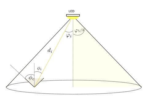
We consider an indoor downlink VLC system realized by a LOS communication link as shown in Fig. 1. The channel gain between the transmitting LED and the receiving PD is given by
| (1) |
where represents the receiver PD area, denotes the distance between the LED and the PD, is the angle of emergence with respect to the transmitter axis, is the angle of incidence with respect to the receiver axis, is the field of view (FOV) of the PD, is the gain of the optical filter and is the gain of the optical concentrator, which is expressed as
| (2) |
where denotes the corresponding refractive index. Moreover, in (1) is the Lambertian radiant intensity of the transmitting LEDs, which can be expressed as
| (3) |
where is the order of Lambertian emission, calculated as
| (4) |
with denoting the transmitter semi-angle at half power. Moreover, the noise at the receiving terminal is drawn from a circularly-symmetric Gaussian distribution of zero mean and variance
| (5) |
where and are the variances of the shot noise and thermal noise, respectively.
III Amplitude, Phase and Quadrature (APQ) Modulation
In order to transmit an M-ary modulation signal, we categorize each of the M symbols by three parameters, namely, amplitude, phase and quadrant. Each one of these parameters is represented by a unipolar PAM signal, then the three signals are superimposed in the power domain and transmitted simultaneously. As a result, the circular constellation is transformed into three different linear constellations in order to fit into the constraints of IM/DD. The idea of power domain superposition is based on assigning different power levels for the different signals, so that the receiving terminal can perform SIC and extract and decode each of the three signals separately. Thus, the proposed APQ scheme can be utilized to transmit high order modulations using a single LED and a single PD.
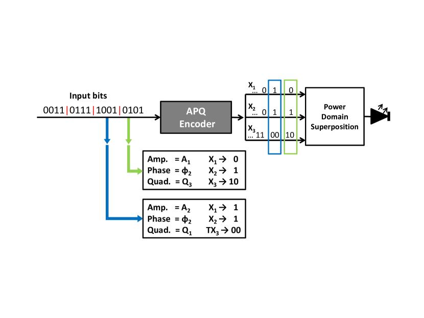
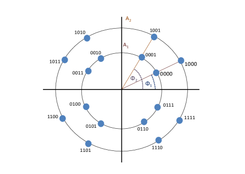
For example, the 16 amplitude and phase-shift keying (APSK) constellation shown in Fig. 3, can be represented by the signals , and , where is a 2-PAM signal representing the two possible amplitude levels (i.e., ), is a 2-PAM signal representing the two possible phase values ( i.e., ) and is a 4-PAM signal representing the four different quadrants of the constellation. The APQ encoder is shown in Fig. 2. The three signals are superimposed in the power domain and sent as a single signal. To this end, different power levels are assigned for the three signals to facilitate SIC at the receiver. We implement simple fixed power allocation (FPA), where the power values are calculated as
| (6) |
where and . Consequently, the transmitted signal can be written as
| (7) |
At the receiving terminal, given that , is directly decoded regarding and as noise. Once decoded, is subtracted from the received signal, yielding , where , then can be decoded and subtracted and finally can be decoded.
IV Error Rate Analysis
The symbol error rate (SER) in APQ modulation can be expressed as:
| (8) |
where , and are the error probabilities in detecting the amplitude, phase and quadrant signals, respectively.
For the case of 16-ary APQ modulation, and are represented by 2-PAM signals whereas is represented by a 4-PAM signal. The error probability in detecting the amplitude signal, , can be written as
| (9) | ||||
where and represent all the possible combinations of the interference caused by and , respectively and denotes the power level of the level in the 4-PAM signal. After decoding and subtracting , the error probability in detecting the phase signal, , can be written as
| (10) |
where
| (11) | ||||
and
| (12) |
Its is noted here that represents the residual interference caused by the detection errors in the first detection stage.
Finally, the error probability in detecting the quadrant signal, , can be written as
| (13) |
where
| (14) | ||||
and
| (15) |
V Benchmark Model
For the purpose of comparison and evaluation, we implement the optical GSSK scheme. In GSSK, an M-ary modulation scheme is transmitted using a total of transmitting LEDs. The number and position of the ones and zeros in the symbol to be transmitted determine which groups of LEDs transmits during the symbol duration. To this effect, different combinations of active and idle LEDs are used to represent the different constellation symbols. Each LED transmits an on-off keying (OOK) signal, and the channel state information (CSI) available at the receiving terminal is exploited to determine the combination of active LEDs, and thus, the intended symbol. A detailed analysis and performance evaluation of GSSK can be found in[18, 20, 19]. It is worth noting that, GSSK is highly dependent on the channel gain differences of the spatially separated LEDs. Consequently, the existence of similar channel gains, which is typical in VLC due to the channel symmetry, results in detrimental error performance. In this case, multiple PDs can be used to create channel gain variations at the receiving terminal in order to realize acceptable error performance, as demonstrated in [18].
VI Results and Discussions
In this section, we evaluate the performance of the proposed APQ scheme by considering different setup scenarios, which are based on the system model presented in Section II. The obtained results are compared to the benchmark model presented in Section V under the same average power constraints to ensure comparability. We consider a m3 room with a maximum of five high brightness white LEDs and a single PD. We assume that the transmitting LEDs are located at a height of m, while the receiving PDs are placed at a height of m. The used simulation parameters are shown in Table I, while the front-ends’ coordinates are shown in Table II.
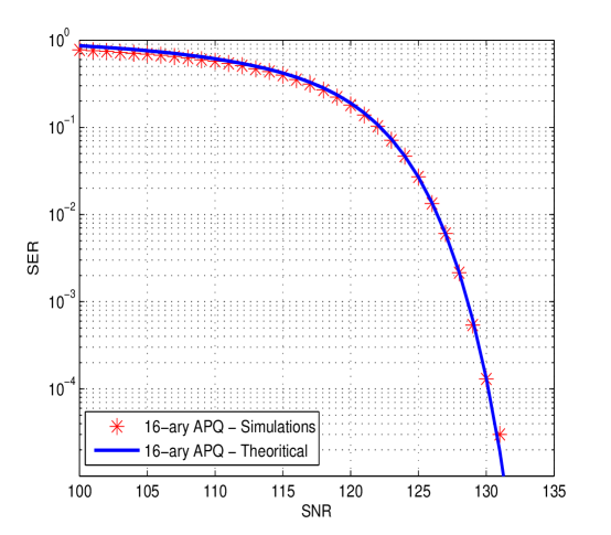
First, we validate the SER expression derived in Section IV. Fig. 4 illustrates the SER performance of 16-ary APQ scheme with regard to the transmit signal-to-noise-ratio (SNR). Since the channel gain is in the order of , the corresponding results exhibit an offset of about dB with respect to the SNR at the receiver site. It is shown that the derived analytical results are in excellent agreement with the respective Monte Carlo simulation results.
| Description | Notation | Value |
|---|---|---|
| LED power | 0.25 W | |
| Transmitter semi-angle | ||
| FOV of the PDs | ||
| Physical area of PD | ||
| Refractive index of PD lens | ||
| Gain of optical filter | ||
| Data rate |
| LED | Coordinate | PD | Coordinate |
|---|---|---|---|
| Tx1 | (2-d,2-d,3) | Rx1 | (1,1,0.75) |
| Tx2 | (2+d,2+d,3) | Rx2 | (2.1,2.2,0.75) |
| Tx3 | (2,2,3) | Rx3 | (2,2,0.75) |
| Tx4 | (2-d,2+d,3) | ||
| Tx5 | (2+d,2-d,3) |
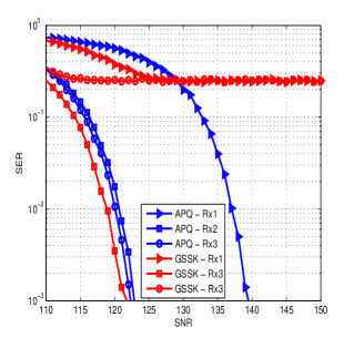
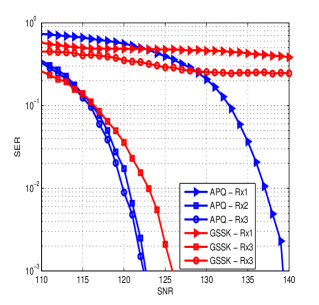
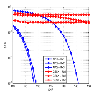
Next, we examine the SER performance of the proposed APQ scheme, and compare it to the performance of GSSK when the distance between the GSSK transmitters on the x- and y-axis is m. This setup, adopted in [18], presents a best case scenario for GSSK, as the transmitters are widely spaced resulting in considerable channel gain differences. On the basis of this setup, we simulate the SER performance for various static locations of the receiving PD, i.e., when the PD is located close to the room boundaries, close to the room center, and exactly in the center of the room. The different locations are denoted by Rx1, Rx2 and Rx3 respectively. Fig. 5 shows that, while GSSK outperforms APQ for the scenario when the receiving PD is located in the proximity of the room center, the proposed APQ scheme provides a good performance regardless of the location of the PD. It is also evident that GSSK fails to provide meaningful communication link when the receiving PD is located in the room center or at the boundaries. This is due to the identical channel gains caused by symmetry, that diminishes the spatial modulation.
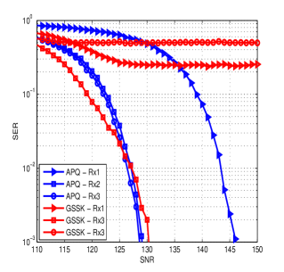
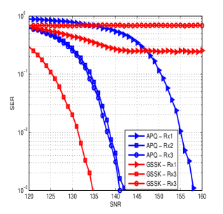
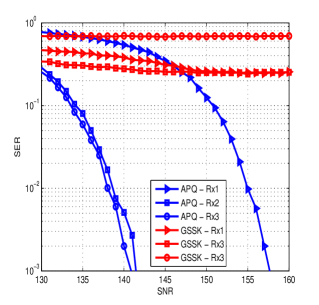
Next, we examine the effect of the LEDs’ locations on the performance of GSSK. To this end, we simulate the SER for m, which is a typical spacing that has been considered in [21]. Fig. 6 demonstrates the effect of similar channel gains on the performance of GSSK, and shows that the proposed APQ scheme provides superior performance compared to GSSK under the existence of similar channel gains.
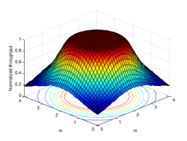
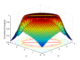
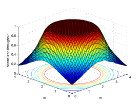
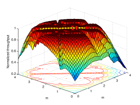
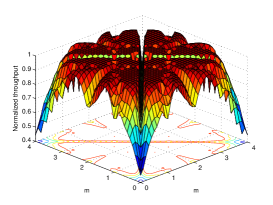
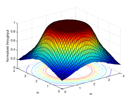
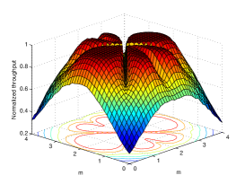
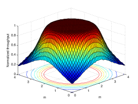
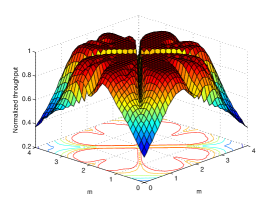
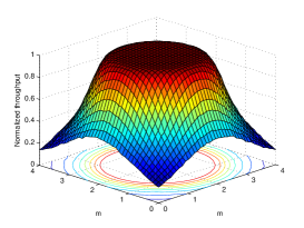
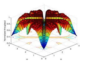
Next, we investigate the achievable system throughput across the simulation area. Fig. 7 and 8 show the normalized achievable throughput for APQ and GSSK for m and m, respectively. The results are obtained for the case of transmitting 3 bits/symbol, 4 bits/symbol and 5 bits/symbol, under fixed transmit SNR of dB, dB and dB respectively. It is evident that APQ achieves uniform throughput levels across the majority of the simulation area, while a throughput degradation occurs at the boundaries. This is an expected behaviour as the user is receiving from a single LED, which is considered a small cell that serves users within its proximity. On the other hand, GSSK suffers huge throughput non-uniformity due to the similarities between the channel gains observed by the receiving terminal. This throughput non-uniformity hinders the reliability of the communication link, as the user may encounter a substantial performance loss while moving in the coverage area of the transmitting LEDs.

VII Conclusions
In this paper, we proposed a novel APQ modulation scheme that is specifically tailored to the requirements imposed by IM/DD based VLC systems. The proposed scheme transmits high order modulation signals by decomposing the amplitude, phase and quadrant information of each symbol, and transmitting the obtained information simultaneously in the power domain. We demonstrated the transmission of 8-ary, 16-ary and 32-ary signals using a single LED and a single photo detector, thus, the proposed APQ scheme provides a cost-effective solution to improve the achievable data rates in indoor VLC systems. On the other hand, GSSK requires transmitting LEDs to transmit a -ary signal. Moreover, APQ offers a reliable communication link regardless of the location of the receiving terminal, which makes it suitable for the practical scenarios where the user moves in the proximity of the transmitting LED, while GSSK suffers significant performance degradation when the receiving PD receives similar channel gains from the different transmitting LEDs.
References
- [1] H. Haas, L. Yin, Y. Wang, and C. Chen, “What is LiFi?” J. Lightw. Technol., vol. 34, no. 6, pp. 1533–1544, 2016.
- [2] H. Marshoud, V. M. Kapinas, G. K. Karagiannidis, and S. Muhaidat, “Non-orthogonal multiple access for visible light communications,” IEEE Photon. Technol. Lett., vol. 28, no. 1, pp. 51–54, 2016.
- [3] M. A. Arfaoui, M. D. Soltani, I. Tavakkolnia, A. Ghrayeb, M. Safari, C. Assi, and H. Haas, “Physical layer security for visible light communication systems: A survey,” IEEE Commun. Surveys Tuts., pp. 1–1, 2020.
- [4] H. Abumarshoud, H. Alshaer, and H. Haas, “Dynamic multiple access configuration in intelligent LiFi attocellular access points,” IEEE Access, vol. 7, pp. 62 126–62 141, 2019.
- [5] D. Zheng, H. Zhang, and J. Song, “OFDM with differential index modulation for visible light communication,” IEEE Photon. J., vol. 12, no. 1, pp. 1–8, 2020.
- [6] A. Ibrahim, T. Ismail, K. Elsayed, M. Saeed Darweesh, and J. Prat, “Resource allocation and interference management techniques for OFDM-based VLC atto-cells,” IEEE Access, pp. 1–1, 2020.
- [7] H. Zhang, Y. Yuan, and W. Xu, “PAPR reduction for DCO-OFDM visible light communications via semidefinite relaxation,” IEEE Photon. Technol. Lett, vol. 26, no. 17, pp. 1718–1721, Sep. 2014.
- [8] M. Zhang and Z. Zhang, “An optimum DC-biasing for DCO-OFDM system,” IEEE Commun. Lett., vol. 18, no. 8, pp. 1351–1354, Aug. 2014.
- [9] J. Tan, Z. Wang, Q. Wang, and L. Dai, “Near-optimal low-complexity sequence detection for clipped DCO-OFDM,” IEEE Photon. Technol. Lett., vol. 28, no. 3, pp. 233–236, Feb. 2016.
- [10] X. Ling, J. Wang, X. Liang, Z. Ding, and C. Zhao, “Offset and power optimization for DCO-OFDM in visible light communication systems,” IEEE Trans. Signal Process, vol. 64, no. 2, pp. 349–363, Jan. 2016.
- [11] B. Ranjha and M. Kavehrad, “Hybrid asymmetrically clipped OFDM-based IM/DD optical wireless system,” IEEE J. Opt. Commun. Netw, vol. 6, no. 4, pp. 387–396, Apr. 2014.
- [12] F. Yang, J. Gao, and S. Liu, “Novel visible light communication approach based on hybrid OOK and ACO-OFDM,” IEEE Photon. Technol. Lett, vol. 28, no. 14, pp. 1585–1588, Jul. 2016.
- [13] S. Dissanayake, K. Panta, and J. Armstrong, “A novel technique to simultaneously transmit ACO-OFDM and DCO-OFDM in IM/DD systems,” in Proc. IEEE GLOBECOM Workshops (GC Wkshps), Dec. 2011, pp. 782–786.
- [14] D. Tsonev and H. Haas, “Avoiding spectral efficiency loss in unipolar OFDM for optical wireless communication,” in Proc. IEEE International Conference on Communications (ICC), June 2014, pp. 3336–3341.
- [15] S. Dimitrov, S. Sinanovic, and H. Haas, “Clipping noise in OFDM-based optical wireless communication systems,” IEEE Trans. Commun., vol. 60, no. 4, pp. 1072–1081, Apr. 2012.
- [16] R. Mesleh, H. Elgala, and H. Haas, “Optical spatial modulation,” IEEE J. Opt. Commun. Netw., vol. 3, no. 3, pp. 234–244, Mar. 2011.
- [17] S. Videv and H. Haas, “Practical space shift keying VLC system,” in Proc. IEEE Wireless Communications and Networking Conference (WCNC), Apr. 2014, pp. 405–409.
- [18] W. O. Popoola, E. Poves, and H. Haas, “Error performance of generalised space shift keying for indoor visible light communications,” IEEE Trans. Commun., vol. 61, no. 5, pp. 1968–1976, May 2013.
- [19] Y. Sun, D. K. Borah, and E. Curry, “Optimal symbol set selection in GSSK visible light wireless communication systems,” IEEE Photon. Technol. Lett., vol. 28, no. 3, pp. 303–306, Feb. 2016.
- [20] W. O. Popoola and H. Haas, “Demonstration of the merit and limitation of generalised space shift keying for indoor visible light communications,” J. Lightw. Technol., vol. 32, no. 10, pp. 1960–1965, May 2014.
- [21] T. Fath and H. Haas, “Performance comparison of mimo techniques for optical wireless communications in indoor environments,” IEEE Trans. Commun., vol. 61, no. 2, pp. 733–742, February 2013.