SimMBM Channel Simulator for Media-Based Modulation Systems
Abstract
Media-based modulation (MBM), exploiting rich scattering properties of transmission environments via different radiation patterns of a single reconfigurable antenna (RA), has brought new insights into future communication systems. In this study, considering this innovative transmission principle, we introduce the realistic, two-dimensional (2D), and open-source SimMBM channel simulator to support various applications of MBM systems at sub- GHz frequency band in different environments.
Index Terms:
Media-based modulation (MBM), sub-6 GHz spectrum, reconfigurable intelligent surface (RIS).I Introduction
The fifth generation (5G) technology envisions enabling numerous new applications with diverse characteristics including low-latency, high reliability, high data rate, energy efficiency and security under three core use-cases: ultra reliable low-latency communications (uRLLC), enhanced mobile broadband (eMBB) and massive machine type communications (mMTC) [1]. While mMTC aims to provide connectivity of the massive number of devices that intermittently send or receive small amount of data, uRLLC applications are anticipated to deal with the stringent requirements on ultra reliability and ultra low-latency for mission critical transmissions. On the other hand, eMBB targets extended coverage, extreme data rates and huge amount of data transfer.
Multiple-input multiple-output (MIMO) systems play a pivotal role to overcome the high data rates requirements of 5G and beyond technologies [1]. Although, millimeter wave (mmWave) and massive MIMO (mMIMO) systems are considered as promising transmission techniques, their inevitably high energy consumption leads researchers to consider more energy efficient solutions [2]. As these studies continue to expand, index modulation (IM) techniques has emerged as a challenging candidate for the future communication technologies, which achieve high data rates by exploiting indices of main pillars of a basic communication system in a clever manner to convey extra information [2].
Media based modulation (MBM), which is one of the prominent IM techniques and uses rich scattering characteristics of wireless environments via exploiting the signatures of different radiation patterns of a reconfigurable antenna (RA), adds a wholly new aspect to future wireless transmission technologies.
This creative transmission technique has attracted a growing interest in the literature. In [3], the authors emphasize significant gains of the MBM system using RF mirrors for practical channel realizations compared to classical single-input multiple-output (SIMO) and MIMO systems. In the follow-up studies, different space-time block coding (STBC) techniques are integrated with the MBM transmission scheme to achieve numerous orders of transmit diversity gains [4, 5]. Also, multi-user and massive MIMO implementations of the MBM system are reported in [6]. For further discussion, we refer the interested reader to [7] and the references therein.
| InH | UMi | UMa | |||||
| LOS | NLOS | LOS | NLOS | LOS | NLOS | ||
| Delay spread (DS) ) | |||||||
| AoD spread (ASD) ) | |||||||
| AoA spread (ASA) ) | |||||||
| AoA/AoD distribution | Laplacian | Wrapped Gaussian | Wrapped Gaussian | ||||
| Number of clusters | |||||||
| Number of rays per cluster | |||||||
| Cluster ASD | |||||||
| Cluster ASA | |||||||
Reconfigurable intelligent surface (RIS) technology is also considered as a potential application to deal with energy efficient and cost-effective network requirements of 5G and beyond systems [8]. An RIS adapts the propagation environment of a communication system in a constructive manner through controllable passive electromagnetic materials that only induce phase shifts without any power supply and complicated signal processors [9]. These low-cost and practical use of RIS has led proliferation of RIS-aided communication systems under diverse research areas [2]. Indeed, recent studies present physical channel models for RIS-aided mmWave communication systems [10, 8, 11], while [10] and [8] introduce an open-source SimRIS channel simulators to model propagation characteristics of mmWave channels in presence of RISs.
In this study, considering International Mobile Telecommunications-Advanced (IMT-Advanced) recommendations [12], the SimMBM channel simulator is released for simulating realistic and two-dimensional (2D) MBM transmission channels that are pertinent to sub- GHz [12] applications of specific indoor hotspot (InH), urban micro (UMi) and urban macro (UMa) network configurations. Unlike the classical MBM studies [7, 4, 5, 6] that consider RF mirrors around transmit antenna(s) to create questionably independent channel state realizations, in SimMBM, we utilize a real RA with four radiation patterns [13] that inherently capable of generating channel variations, while a generalization to the case of multiple radiation patterns is straightforward. This open-source channel simulator offers different environment types (InH, UMi and UMa), and allows locations variations.
The remainder of the paper is organized as follows. We present the overall structure of the channel simulator, including the MBM systems and IMT-Advanced channel modeling concepts in Section II. In Section III, the channel correlation and capacity measurements of the MBM systems are provided. Our numerical results are presented in Section IV and conclusions are given in Section V.
| LOS Probability | |
|---|---|
| InH | |
| UMi | |
| UMa |
II SIMMBM Channel Simulator
In this section, the SimMBM channel simulator, which generates the MBM transmission channels characterized by the IMT-Advanced standards at sub- GHz frequency band, is introduced.
II-A IMT-Advanced Channel Modeling
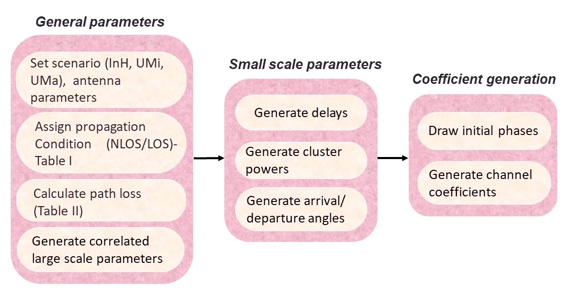
The IMT-Advanced systems proving extensive transmission protocols for mobile communications and broadband connectivity are growingly deployed worldwide in today’s wireless communication systems [1]. In this study, the proposed SimMBM channel simulator, which produces MBM channels in various indoor and outdoor environments, follows IMT-Advanced channel modeling procedure illustrated in Fig. 1 [12].
In this study, first, we consider a generic single-input single-output (SISO) system whose propagation environment is characterized by IMT-Advanced channel models that consist of multiple clusters, each composing a number of sub-rays with similar characteristics referred to as scatterers. Each cluster is characterized by large scale parameters which are statistical parameters such as delay spread (DS) and angular spread (AS) that follow the distributions given in Table I [12]. Then, these parameters are employed to assign delay , power , departure and arrival angles to each path, which are often referred to as small scale parameters.
| Scenario | |||||
|---|---|---|---|---|---|
| InH | LOS | ||||
| NLOS | |||||
| UMi | LOS | ||||
| NLOS | |||||
| UMa | LOS | ||||
Accordingly, after specifying a scenario among the available network configurations InH, UMi and UMa, distance-dependent line of sight (LOS) probability , for being the 2D distance between the transmitter (T) and the receiver (R), is determined as given in Table II [12]. Please note that throughout this paper, the terms ”T” and ”R” will be used to refer transmitter and the receiver, respectively.
After determining whether a LOS propagation link exists between the T and the R, the attenuation caused by path loss and shadowing fading (SF), in decibel (dB), is calculated, using the path loss parameters given in Table III [12], as follows
| (1) |
where is operating frequency at the sub- GHz frequency band.
Assume and respectively represent the number of total clusters and number of scatterers within each cluster, and denotes the th scatterer of the th cluster. Therefore, considering IMT-Advanced channel parameters in Table I [12], the geometric channel between this generic SISO system is constructed as [12]
| (2) |
where is the LOS component, is the initial phase uniformly distributed between , i.e., , while and are the transmit and receive antenna gains in the direction of the th path, respectively. In (2), is assumed to be independent identically distributed (i.i.d) complex Gaussian random variable with zero mean and variance for being the average power of the path and , while is determined as
| (3) |
where is Bernoulli random variable with probability, indicating existence of a LOS link between the T and R. and are the transmit and the received antenna gain in LOS direction, respectively.
II-B RA-based MBM Channels
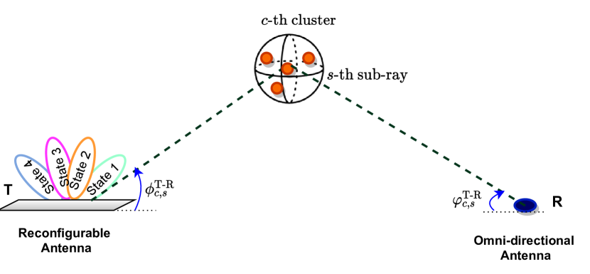
In this study, considering IMT-Advanced standards for sub- GHz applications described above [12], we consider propagation environment of a SISO system whose schematic diagram is given in Fig. 2. It is assumed that a single RA with four different directional radiation patterns operating at GHz frequency [13] is employed at T, while R is equipped with an omni-directional antenna that collects signals with unit gain in all directions.
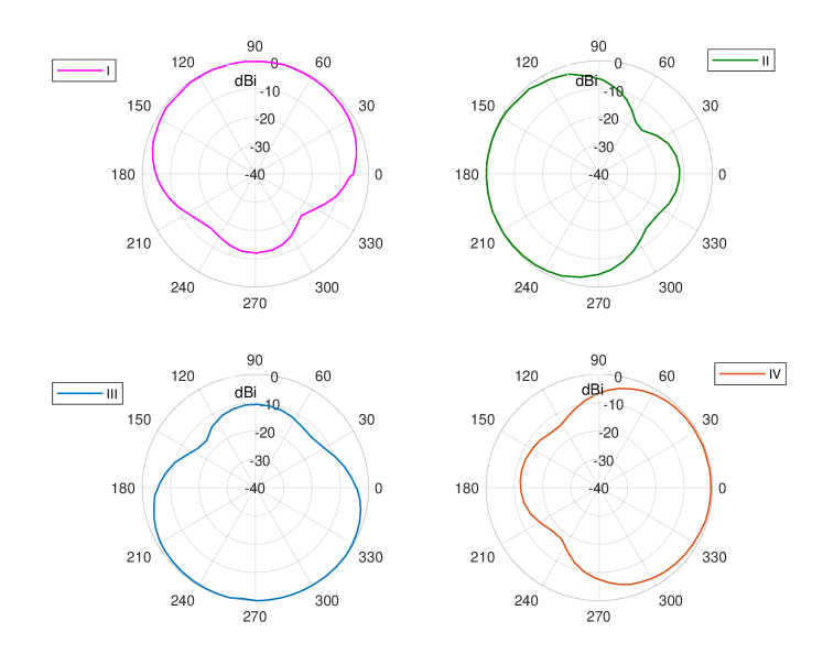
The considered RA exploits four arc dipoles as radiating elements and manipulates the radiation direction by ON/OFF status of PIN diodes [13], which create four directional radiation patterns presented in Fig. 3. It is worth-noting that the radiation patterns of this RA are extracted from 2D polar plots given in [13] by using a software program [14]. Moreover, this RA with pattern diversity can steer in azimuth plane and allows us to perform the classical MBM concept [15, 7] between T and R. Therefore, considering the above azimuth beam steering RA [13], an RA-based SISO-MBM system is constructed.
In this system, considering classical MBM transmission principle, the incoming information bits determine one out of four radiation patterns of the RA [13] to be activated in each transmission interval by switching ON/OFF status of the corresponding PIN diode. Therefore, considering the geometry-based IMT-Advanced channels reported in preceding subsection, the transmission channel of the SISO-MBM system is constructed as
| (4) |
where is the antenna gain of the th state in direction of angle for denoting the index of the active radiation pattern.
Furthermore, to enhance the spectral efficiency of the SISO-MBM scheme, it is generalized for a MIMO configuration with uniform linear array (ULA) deployment of RA antennas at T and omni-directional antennas at R. Further, in this MIMO-MBM system, by assigning bits to each RA, all available transmit RAs are used for transmission through their active radiation patterns which are determined via the incoming bits. Therefore, the channel coefficient between the th transmit RA and th received antenna is constructed as follows
| (5) |
In (5), for being distance between the T and R, is the gain of the th pattern corresponding to th transmit RA, , and is the distance between adjacent antennas, which is assumed to be , and is the wavelength. Therefore, the overall channel matrix between T and R, , becomes
| (6) |
where is the LOS component, and denote the transmit and received array response vectors at the corresponding departure and arrival angles, respectively. In (6), the ULA-based RA array response vector (including gains) is
| (7) |
while ULA-based omni-directional receiver array vector is
| (8) |
II-C RIS-aided MBM Systems
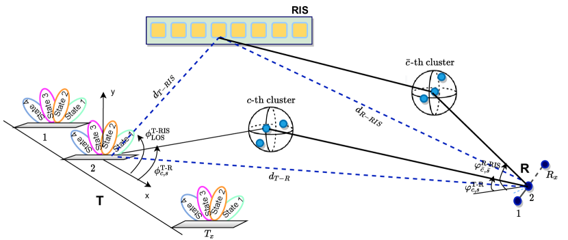
Since the RIS technology offers cost-effective solutions for future communication systems, there is a growing body of literature on novel RIS-aided transmission system designs [2]. In that sense, in order to enhance the signal quality of the aforementioned MIMO-MBM schemes, an RIS is integrated between T and R. In this new RIS-aided MBM system, to ensure consistency with the above 2D IMT-Advanced channel models, a ULA-based RIS with spaced passive reflecting elements is placed between T and R of the MIMO-MBM system as illustrated in Fig. 4. Furthermore, in this system, in order to get a significant gain from the RIS, we assume the RIS being close enough to T to ensure pure LOS links. On the other hand, R is assumed to be sufficiently far from the RIS and T to allows multi-path propagation in T-R and R-RIS links.
Obviously, the multi-path propagation environment of the T-R link corresponds to the MIMO-MBM channel described in the previous subsection. Therefore, the channel matrix characterizing the T-R link becomes as given in (6)-(8).
Likewise, since we assume pure LOS links in T-RIS link, considering IMT-Advanced models, the LOS channel of T-RIS link is obtained as
| (9) |
where is the LOS distance of the T-RIS path, and symbolizes the gain of the RIS elements, which is assumed to be [8]. In addition, is the attenuation between T-RIS link that can be calculated from (1), while and respectively are the array response vectors of the T and RIS in LOS direction. Thus, is calculated as in (7), is obtained as follows
| (10) |
On the other hand, for the R-RIS link, we consider a multi-path propagation environment. Let and respectively symbolize the number of clusters and scatterers within each cluster in R-RIS link. Then, the R-RIS channel matrix is constructed as
| (11) |
where is the distance from the RIS to R, is the LOS component which is separately obtained from multi-path propagation, and and respectively are the array response vectors at and directions.
After all, the composite channel of the RIS-aided MBM system is constructed by combinations of the direct and the reflected paths as , where is the diagonal reflection matrix of the RIS. It is worth stating that diagonal reflecting matrix of is constructed considering [9] for SISO-MBM and [16] for MIMO-MBM systems.
Consequently, the received signal of the RIS-aided MIMO-MBM system becomes
| (12) |
for being the all-one transmission signal vector whose each element corresponds to an unmodulated carrier signal, while is additive white Gaussian noise (AWGN) vector composing i.i.d. random variables, where each follows distribution.
III Correlation and Capacity Analysis
This section provides correlation and capacity analyses of the MBM systems.
III-A Correlation Analysis
Although channel correlation is a key factor determining robustness and efficiency of the MBM systems, there has been little discussion about the realistic correlation models for MBM [7]. In this study, although the same propagation environment is considered, the pattern diversity of the RA in Fig. 3 [13] which exploits the RF characteristics of the environment, allows signals from different radiation patterns to follow different paths in arriving the receiver.
In this subsection, the channel correlation caused by different radiation patterns of the RA [13] is computed through Monte Carlo simulations. For this reason, the SISO-MBM scheme whose transmit channel coefficient corresponding to the th RA pattern given in (2), is considered. For being number of total sub-rays, the cross channel correlation corresponding to and modes of the RA can be calculated from
| (13) | |||
| (14) |
where , and is the expectation.
Above all, considering IMT-Advanced NLOS InH scenario, the cross correlation matrix of the SISO-MBM scheme is calculated via extensive computer simulations as follows
| (15) |
The resulting correlation matrix shows a manageable correlation between the channels generated by the radiation patterns of the RA [13], indicating the compatibility of the reference RA [13] for the MBM transmission.
III-B Capacity Analysis
The recent studies indicate that as in the classical MIMO transmission schemes, the channel capacity of IM-based systems is not dependent on the transmit signal constellations [17, 18]. Moreover, in [18], the capacity of the classical MIMO systems is calculated as an upper bound for the capacity of the IM-based MIMO systems. Therefore, considering [18], the capacity of the RIS-aided MIMO-MBM systems can be upper bounded using (12) as
| (16) |
where is the transmission power and is an identity matrix with dimensions.
IV Simulation Results
In this section, to test our new channel simulator, we present a number of numerical results on the capacity of various MBM-based systems at sub- GHz band. In all simulations, the noise power is considered to be dBm. Also, it should be noted that for InH scenarios, the 2D coordinates of T, R and RIS are given as (,), (,) and (,), in meters (m), respectively. Additionally, for UMi and UMa scenarios the coordinates of T, R and RIS are assumed to be (,), (,) and (,) m.
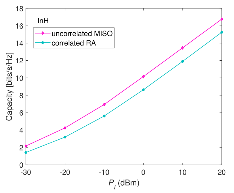
In Fig. 5, considering IMT-Advanced InH scenario, the capacity of the RA-based system [13] that generates low-correlated channel variations is compared with uncorrelated classical MISO transmission schemes that employs four transmit and a single received omni-directional antennas in transmission. The results indicate that the performance of the four-state RA [13] is slightly behind the uncorrelated multi-antenna system. This comparison is significant in understanding the effect of low channel correlations on the performance of MBM systems.
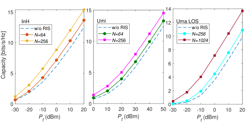
In Fig. 6, the capacity of the SISO-MBM with/without assistance of the RIS is investigated in different environments. It is clear from the results that since outdoor environments (UMi, UMa) experience higher attenuation in the direct T-R link, they require higher number of reflecting elements in RIS to tackle this performance degradation.
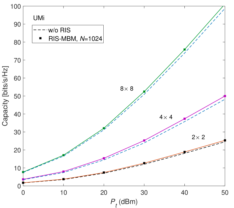
In Fig. 7, the capacity results of the MIMO-MBM systems in UMi environment are demonstrated. It can be deduced from the results that as MIMO configuration enlarged, a linear relation between the path attenuation and capacity of the MIMO-MBM systems is observed. Therefore, the effect of the RIS on the system performance is hardly seen.
V Conclusion
In this paper, a 2D, open-source and easy-to-use physical channel simulator, SimMBM, enabling users to generate communication channels of the various MBM implementations at sub- GHz frequency spectrum, has been presented. The proposed channel simulator offers flexibility in performing different MBM systems for varying localizations, scenarios and RA adaptations and reveals the potential of emerging MBM systems in realistic conditions.
References
- [1] M. Series, “Guidelines for evaluation of radio interface technologies for IMT-2020,” Report ITU-R M.2412-0, Tech. Rep., Oct. 2017.
- [2] E. Basar, M. Di Renzo, J. De Rosny, M. Debbah, M.-S. Alouini, and R. Zhang, “Wireless communications through reconfigurable intelligent surfaces,” IEEE Access, vol. 7, pp. 116 753–116 773, Aug. 2019.
- [3] A. K. Khandani, “Media-based modulation: Converting static Rayleigh fading to AWGN,” in IEEE Int. Symp. Information Theory, July 2014, pp. 1549–1553.
- [4] E. Basar and I. Altunbas, “Space-time channel modulation,” IEEE Trans. Veh. Technol., vol. 66, no. 8, pp. 7609–7614, Feb. 2017.
- [5] Z. Yigit and E. Basar, “Space-time media-based modulation,” IEEE Trans. Signal Process., vol. 67, no. 9, pp. 2389–2398, Mar. 2019.
- [6] B. Shamasundar, S. Jacob, L. N. Theagarajan, and A. Chockalingam, “Media-based modulation for the uplink in massive MIMO systems,” IEEE Trans. Veh. Technol., vol. 67, no. 9, pp. 8169–8183, May 2018.
- [7] E. Basar, “Media-based modulation for future wireless systems: A tutorial,” IEEE Wireless Commun., vol. 26, no. 5, pp. 160–166, July 2019.
- [8] E. Basar and I. Yildirim, “Indoor and outdoor physical channel modeling and efficient positioning for reconfigurable intelligent surfaces in mmWave bands,” arXiv preprint arXiv:2006.02240, 2020.
- [9] E. Basar, “Transmission through large intelligent surfaces: A new frontier in wireless communications,” in IEEE European Conf. Netw. and Commun. (EuCNC), June 2019, pp. 112–117.
- [10] E. Basar and I. Yildirim, “Reconfigurable intelligent surfaces for future wireless networks: A channel modeling perspective,” to appear in IEEE Wireless Comm., Mar. 2021.
- [11] J. He, H. Wymeersch, L. Kong, O. Silvén, and M. Juntti, “Large intelligent surface for positioning in millimeter wave MIMO systems,” in 2020 IEEE 91st Veh. Technol. Con. (VTC2020-Spring), May 2020, pp. 1–5.
- [12] M. Series, “Guidelines for evaluation of radio interface technologies for IMT-Advanced,” Report ITU-R M.2135-1, Tech. Rep., Dec. 2009.
- [13] G. Jin, M. Li, D. Liu, and G. Zeng, “A simple planar pattern-reconfigurable antenna based on arc dipoles,” IEEE Antennas and Wireless Propagation Lett., vol. 17, no. 9, pp. 1664–1668, Aug. 2018.
- [14] A. Rohatgi, “WebPlotDigitizer.” [Online]. Available: http://www.https://apps.automeris.io/wpd/
- [15] Y. Naresh and A. Chockalingam, “On media-based modulation using rf mirrors,” IEEE Trans. Veh. Technol., vol. 66, no. 6, pp. 4967–4983, Oct. 2016.
- [16] Z. Yigit, E. Basar, and I. Altunbas, “Low complexity adaptation for reconfigurable intelligent surface-based MIMO systems,” IEEE Commun. Lett., vol. 24, no. 12, pp. 2946–2950, Dec. 2020.
- [17] R. Mesleh and A. Alhassi, Space Modulation Techniques. Wiley Online Library, 2018, vol. 288.
- [18] T. L. Narasimhan and A. Chockalingam, “On the capacity and performance of generalized spatial modulation,” IEEE Commun. Lett., vol. 20, no. 2, pp. 252–255, Nov. 2015.