Energy Release Rate, the crack closure integral and admissible singular fields in Fracture Mechanics
Abstract
One of the assumptions of Linear Elastic Fracture Mechanics is that the crack faces are traction-free or, at most, loaded by bounded tractions. The standard Irwin’s crack closure integral, widely used for the computation of the Energy Release Rate, also relies upon this assumption. However, there are practical situations where the load acting on the crack boundaries is singular. This is the case, for instance, in hydraulic fracturing, where the fluid inside the crack exerts singular tangential tractions at its front. Another example of unbounded tractions is the case of a rigid line inclusion (anticrack) embedded into an elastic body. In such situations, the classical Irwin’s crack closure integral fails to provide the correct value of the Energy Release Rate. In this paper, we address the effects occurring when square-root singular tractions act at the boundary of a line defect in an elastic solid and provide a generalisation of Irwin’s crack closure integral. The latter yields the correct Energy Release Rate and allows broad applications, including, among others, hydraulic fracturing, soft materials containing stiff inclusions, rigid inclusions, shear bands and cracks characterized by the Gurtin-Murdoch surface stress elasticity. We present the results in the most general form, where six Stress Intensity Factors are present: three of them are classical SIFs corresponding to the modes I-II-III and computed under the assumption of homogeneous boundary conditions at the defect surfaces, while the other three SIFs are associated with singular admissible tractions (those that lead to a finite ERR value). It is demonstrated that this approach resolves an ambiguity in using the same SIF’s terminology in the cases of open cracks and rigid inclusions, among other benefits.
1 Introduction and motivation
The classical Linear Elastic Fracture Mechanics (LEFM), in the Griffith-Irwin formulation, assumes that the effects of plasticity and dissipative processes are limited to a small crack-tip zone. It also assumes that tractions applied at crack faces are either zero or bounded (if they are singular, the singularity must be weaker than the square-root one).
In (Wrobel et al., 2017), the authors encountered the need to incorporate singular tractions at the crack tip being of the same order as the classic square-root singularity in the study of Hydraulic Fracture (HF). HF is a phenomenon where a crack in an elastic body is driven by a high-pressure moving fluid (fracking is an example of a technological process, sub-glacial drainage and underground magma flow are examples of natural processes). The typical approach has been to retain the LEFM framework and to assume that the fluid follows a laminar (Poiseuille) flow. The fluid may also leak-off into the surrounding domain, typically is assumed to follow the Carter Law. The fracture growth is therefore determined by the solid-fluid coupling: i) the tractions on the fracture walls induced by the fluid, ii) the ability of the solid medium to resist this action, both in the direction of crack extension (fracture toughness) and orthogonal to the fluid flow (elastic response). The long-time behaviour of the fracture is typically determined by the rate of fluid loss to leak-off effects.
Due to the strong non-linearity of the solid-fluid interaction, as well as the degeneration of the governing equations at the fracture tip (see (11)), the modeling of HF began with the use of simplified 1D models: PKN, KGD (plane strain) and radial (penny-shaped). While more advanced models of HF have been developed (reviews can be found in (Adachi et al., 2007; Lecampion et al., 2018)), these 1D models continue to form the basis of investigations into the underlying physical processes of HF. For example, the crucial role of the tip asymptotics in solution behaviour was first observed in (Spence and Sharp, 1985) and later expanded upon in (Garagash et al., 2011).
The solvers employing the fracture front asymptotics currently constitute the state-of-the-art approaches; their success has been demonstrated experimentally by (Bunger and Detournay, 2008; Lecampion et al., 2017). The solvers tend to utilize the level set method first outlined by (Peirce and Detournay, 2008), with a review given by (Peirce, 2016), while an open-access general-purpose solver PyFrac was recently released by (Zia and Lecampion, 2020). An alternative approach is the development of explicit solvers based on the use of the so-called “speed equation”, a form of Stefan-type boundary condition that tracks the fracture front (Kemp, 1990; Linkov, 2011, 2012; Mishuris et al., 2012), that has been implemented by (Wrobel and Mishuris, 2015; Perkowska et al., 2016; Peck et al., 2018a, b).
All those results have been obtained under the commonly accepted assumption that the shear tractions induced by the fluid on the fracture walls can be neglected. Recently, however, the role of those tractions - previously ignored even though being singular - has come under increased examination. A preliminary analysis in the framework of the KGD model (Wrobel et al., 2017) demonstrated that the shear stress induced by the fluid on the crack surfaces changes the asymptotics near the crack tip. Naturally, it has a significant effect on the evaluation of the fracture Energy Release Rate (ERR). It was demonstrated that the differing tip asymptotics offered an alternative physical explanation for the transition in fracture growth behaviour which occurs over time (between viscosity and toughness dominated regimes), while a follow-up investigation demonstrated a possible impact on fracture redirection (Perkowska et al., 2017; Wrobel et al., 2021b) and examined the dependence of these effects on fluid rheology (Wrobel et al., 2021a).
It should be noted for the sake of completeness that, although the effects of singular tangential tractions have already attracted some attention (Shen and Zhao, 2017, 2018; Shen et al., 2020; Papanastasiou and Durban, 2018), the extent to which shear stress on the fracture walls impacts hydraulic fracturing growth remains a controversial issue (see, for example, (Linkov, 2018; Wrobel et al., 2018)). However, this controversy primarily concerns only the role of the tangential tractions on the elasticity equation used within that framework, and does not affect the assessment of the ERR obtained in the original works by (Wrobel et al., 2017; Perkowska et al., 2017).
The aforementioned incorporation of fluid shear stresses into planar HF (Wrobel et al., 2017, 2018) required a re-examination of the LEFM due to the square root singularity of the shear traction on the boundary of the fracture at the crack tip, which had previously been ignored. As a result, the asymptotics of the problem needed to be reconsidered, and the corresponding Energy Release Rate (ERR) to be recomputed (following the general principles introduced, independently, by (Cherepanov, 1967, 1968) and (Rice, 1968)). The most important discrepancy arising from these investigations however was that the ERR computation obtained in (Wrobel et al., 2017; Perkowska et al., 2017) appears to be in contradiction with that computed in accordance with the standard Irwin’s crack closure integral, widely used for the computation of the Energy Release Rate in the framework of the classical LEFM (see Sect. 2.1).
This discrepancy demonstrates the lack of a general framework within LEFM for incorporating the effects of square-root singular tractions acting on line-type defects (eg. fractures or rigid inclusions within an otherwise homogeneous material), although some special cases have been considered (see, for example, (Atkinson and Craster, 1995)). The first evaluation of the energy release rate for stiffener growth was given in (Bigoni et al., 2008), further developed in (Dal Corso and Bigoni, 2010, 2008) and supported by experimental results on the singular stress state near a stiff lamellar inclusion in (Dal Corso et al., 2008; Noselli et al., 2010) and shear bands (Goudarzi et al., 2021). Another relevant example is given by the crack growth with Gurtin-Murdoch surface stresses on the fracture wall (see (Gorbushin et al., 2020) and discussion therein).
Thus, there is a need to extend the framework of LEFM to cases where the square-root singular tractions are also present. This work aims to establish such a framework in its general setting, extending the classical LEFM. We show that there are six Stress Intensity Factors involved in the analysis: three of them are the classical SIFs corresponding to the modes I-II-III and computed under the assumption of homogeneous boundary conditions at the defect surfaces, while the other three SIFs are associated with singular admissible tractions (those that lead to a finite ERR value). The analysis involves deriving the Energy Release Rate (ERR) through two separate approaches.
The first is Rice’s -integral approach using the formula (14) that leads to the general form of the ERR:
| (1) |
where are three new SIFs associated with the three coefficients in the leading term of the singular tractions by , , .
The second approach is through the principle of virtual work that leads to the generalized Irwin’s formula:
| (2) |
Details on the notations used in these formulas are given in the main text (see equations (28) and (51)). However, even from first glance it is clear that these two formulas differ from their classic representations only by the presence of additional terms. We demonstrate that both approaches yield the same, self-consistent, formulation, which reduces to the classical LEFM if the singular tractions vanish (). Moreover, this resolves the aforemention discrepancy in ERR computations.
This paper is structured as follows. In Sect. 2.1 an overview of relevant HF-related results, with tangential tractions induced by the fluid on the crack walls, are given and compared with the expected results from LEFM. Sect. 2.2 introduces examples from other fields of research where line defects experience square-root tangential tractions, further motivating the work. In Sect. 3, the general form of the ERR for a crack loaded by (square-root) singular tractions is derived. This is expanded upon in Sect. 4, with the derivation of the general form of the crack closure integral, alongside details of the stress and displacement fields, for any line defect within an elastic material. In Sect. 5 a comparison of the results with existing ones is given, including a comparison with the classical LEFM. Several special cases are also considered: i) the HF with tangential tractions induced by the fluid, ii) the growth/shrinkage of a thin rigid 2D inclusion, iii) the growth of a Mode III crack with singular tractions on its surfaces, iv) the stress intensity factors for a closed crack. Discussion and concluding remarks are given in Sect. 6.
2 Preliminary results on singular tractions acting along the linear defects
2.1 Hydraulic Fracture with fluid-induced tangential traction on the crack walls
Below we give a short overview of results obtained in the study of hydraulic fracture with shear stress induced upon the crack walls by the fluid, which provides the motivation for this work. In the original paper of (Wrobel et al., 2017), alongside a later extension to the mixed-mode case in (Perkowska et al., 2017; Wrobel et al., 2021b), it was demonstrated that the asymptotics of the displacement and stress fields near the crack-tip () are
| (3) |
| (4) |
where is a local polar coordinate system linked to the crack tip (see Fig. 1), , and are the classical stress intensity factors (SIFs) associated with homogeneous boundary conditions at the crack faces and is the hydraulic shear stress intensity factor (HSSIF) related to the hydraulic shear stress, , induced by the fluid on the crack surfaces (Wrobel et al., 2017). Respective functions , can be found in (Wrobel et al., 2017; Perkowska et al., 2017).

As a result, one can obtain
| (5) |
| (6) |
| (7) |
| (8) |
where is the jump of and are the unit vectors of the local cylindrical coordinate system.
Note that the hydraulic shear stress intensity factor, , is directly related to the mode I SIF, , via the factor
| (9) |
that, in turn, depends on the coefficient, , describing the first term of asymptotics of fluid pressure near the crack tip provided that no lag presents in the process (Wrobel and Mishuris, 2015):
| (10) |
Here, and throughout the paper, is the elastic shear modulus. For details on how the above is derived, we refer a prospective reader to (Wrobel et al., 2017).
The tangential traction induced on the fracture walls in terms of the crack aperture , fluid velocity and the normal pressure , follows from lubrication theory
| (11) |
It is clear that this equation will become degenerate at the crack tip (), as we have the aperture while the fluid pressure and it’s derivative are singular. The asymptotics of the aperture at the crack tip follows from (6), while those of the pressure derivative are obtained from (10)
Thus, the leading term asymptotics of the hydraulic shear stress, i.e. the tangential stress exerted by the fluid on the crack faces, follows immediately as
| (12) |
where the coefficient is related to the hydraulic shear stress intensity factor by
| (13) |
This asymptotic representation (12) – (13) can also be obtained from the jump of .
In the framework of the LEFM, the ERR is computed using the standard -integral arguments (Cherepanov, 1967, 1968; Rice, 1968):
| (14) |
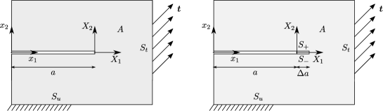
where is a circular contour of radius around the fracture tip, contained in a plane orthogonal to the crack front, is the outward normal to the contour , and is the traction vector along (see Fig. 1).
The respective expression for ERR yields (see (Perkowska et al., 2017)):
| (15) |
which, used as the crack propagation condition, takes the form:
| (16) |
In a particular case of the Mode I this reduces to:
| (17) |
The equivalent of the Irwin criterion (typically ) can be stated in this description as
| (18) |
The right-hand side of the latter can be treated as apparent toughness dependent on the solution at each time step.
On the other hand, one can compute the Energy Release Rate by the classic formula (Irwin, 1958), through the so-called crack closure integral or virtual crack closure integral (Rybicki and Kanninen, 1977; Krueger, 2004):
| (19) |
Note that expression (19) is written in Cartesian coordinates while (3) – (8), used in the computations, are given in the radial coordinates (thus, the vectors and are differently oriented on the line ahead of the crack tip and the crack surfaces). Here and in what follows, the jumps are computed over the crack surfaces, while the averages on the crack front ahead of the tip.
We refer a prospective reader to the first chapter of a fundamental monograph by (Slepyan, 2002) for deep and enlightened discussions on basic concepts in fracture mechanics, ERR computations and fracture criteria.
Substituting the asymptotics (6) – (7) into (19), we have
| (20) |
Surprisingly, this result is different from (15), seemingly contradicting the classical LEFM. This was communicated to us by D. Garagash222private communication.
This apparent discrepancy requires some explanation, and this paper aims to resolve this central paradox by constructing a general framework within LEFM for any singular field of line-type defects (expanding the results from (Atkinson, 1973; Atkinson and Craster, 1995)). However, while the original motivation is within HF, this general framework is of importance to numerous other problems. Some of them are outlined in the next subsection, providing both an additional motivation for the construction of this framework as well as important benchmarks against which to examine its conclusions.
2.2 Singular traction at the defect tip in other physical phenomena
The primary motivation for this work is the Hydraulic Fracture; however, similar problems involving singular tractions and computation of the ERR (or the crack closure integral) arise in other areas of research. Two problems of this kind are discussed below.
2.2.1 Rigid inclusions within biological materials
Consider thin stiff inclusions embedded in a large, soft medium. Such systems are encountered in biomaterials, for example in the study of nanocomposite inclusions within a protein-based bulk material (Goudarzi et al., 2021), or the behaviour of fibrous food during processing such as grinding (Sridhar and Sommer, 2013). In these cases, the inclusions can be modeled as rigid line elements within an infinite elastic isotropic domain.
In the plane strain case, the asymptotic displacement and stress fields near the tip of the inclusion () can be expressed as (Atkinson and Craster, 1995; Goudarzi et al., 2021)
| (21) | ||||
where and are cartesian and polar coordinates, respectively, orientated with respect to the inclusion tip as shown in Fig. 1. Meanwhile, are normalizations of the stress intensity factors of LEFM (see (Noselli et al., 2010)). Similar results can also be obtained for the case of multiple ribbon-like inclusions (Atkinson, 1973). When evaluating the asymptotics (21), the boundary conditions on the inclusion faces are given in terms of displacements, while the resulting tractions acting along the inclusion are:
Thus, it is not only tangential traction that could be singular but the normal traction as well. Interestingly, these stress components represent the symmetric and skew symmetric parts of solution, respectively.
2.2.2 Analysis of fractures in nano-structures accounting for surface effects
Another example, where singular traction acts on defect faces, is the Gurtin-Murdoch model that takes the surface stress notion into account (Gurtin and Murdoch, 1978). This model considers a body where the behaviour of the surface layer is distinct from that of the underlying elastic material, as is the case for certain class of crystals after cleaving. The stress field at the boundary may therefore include an induced singular traction, depending on the problem geometry. This model has been utilized in the study of elastic domains with coupled surface and internal stresses, for example, in problems involving tangential line loading (e.g. (Le et al., 2021)).
Of greater relevance are the models of fracture in elastic material accounting for differences in behaviour of the crack surface and bulk material in Mode I - II (Kim et al., 2011) and Mode III (Kim et al., 2010a, b), with applications to the study of various materials. These papers demonstrated that in some cases the surface stress may eliminate the singularity of the stress field at the crack tip. It was even believed that it is a common feature, however, this is not universally true.
In general, incorporating surface stresses results in smoother solutions than in classic elasticity (see, for example, the analysis of weak solutions in (Eremeyev and Lebedev, 2016; Eremeyev et al., 2021)). Thus, one may expect a reduction of any singularities at the defect tip. However, incorporating surface effects requires a consistent smoothness of the boundary of the domain. Obviously, domains with cracks are not so smooth as required, so some singularities in solutions may still occur.
A more detailed analysis of the stress singularity at the crack tip for a Mode III crack, accounting for Gurtin-Murdoch type surface stress, successfully explained this deviation from the expectations of LEFM (Gorbushin et al., 2020). It was demonstrated that the surface stress effect indeed leads to a square-root singularity of the shear stresses on the surface for the antisymmetric part of the solution and logarithmic singularity for the symmetric one. These results demonstrate that the incorporation of square-root singular tractions into LEFM is still necessary for the analysis of singular field near the defect tips.
3 General form of the Energy Release Rate for a crack loaded by admissible singular traction
We start by analysing the Energy Release Rate (ERR) for a crack loaded by singular tractions acting on the crack faces. The assumed singularity of the applied tractions is of the square-root type, as . Note that the analysis performed here is general, as it involves all possible traction components, both in-plane and out-of-plane. Additionally, both symmetric and skew-symmetric loads are considered.
The complete set of singular tractions is illustrated in Table. 1. Not all traction components are admissible, i.e. not all correspond to a finite ERR (non-admissible tractions are associated with unphysical cases of an infinite ERR). Through asymptotic analysis, it can be concluded that the admissible singular tractions are: symmetric tangential tractions, both in-plane and out-of-plane, and skew-symmetric normal tractions. These tractions produce a stress field with a standard square-root singularity at the crack tip. The non-admissible singular tractions are: skew-symmetric tangential tractions, both in-plane and out-of-plane, and symmetric normal tractions. These tractions produce a stress field with a stronger singularity at the crack tip, namely .
| Type of tractions | Symmetric | Skew-symmetric |
|---|---|---|
| In-plane tangential singular tractions |
![[Uncaptioned image]](/html/2103.17010/assets/x2.png) Admissible
Admissible
|
![[Uncaptioned image]](/html/2103.17010/assets/x3.png) Non-admissible
Non-admissible
|
| In-plane normal singular tractions |
![[Uncaptioned image]](/html/2103.17010/assets/x4.png) Non-admissible
Non-admissible
|
![[Uncaptioned image]](/html/2103.17010/assets/x5.png) Admissible
Admissible
|
| Out-of-plane tangential singular tractions |
![[Uncaptioned image]](/html/2103.17010/assets/x6.png) Admissible
Admissible
|
![[Uncaptioned image]](/html/2103.17010/assets/x7.png) Non-admissible
Non-admissible
|
Remark: For the purpose of this investigation, an admissible traction is one which produces a finite ERR. The justification for this is as follows. In the case when a non-admissible load is applied, the crack propagation is dynamically unstable (as the ERR is infinite). Thus, it will inevitably outrun the source of any predefined singular load acting at the crack tip, and the classical LEFM instead governs the propagation starting from some moment. Conversely, for the continuous application of a singular tangential traction at the crack tip, one requires that the energy induced into the fracture be finite. Therefore, a finite ERR is required (the traction is admissible). Thus, only cases with a finite ERR need be considered in the development of this framework.
The case of in-plane tangential singular traction was analysed by (Wrobel et al., 2017), see Sect. 2.1. We now report the full asymptotic solution, including the ERR for the general case in which all admissible singular tractions act on the crack faces.
The assumed singular tractions acting on the crack faces () have the following crack-tip asymptotics:
| (22) | ||||
where is a positive constant.
Here the three values , and are the multipliers of the leading singular terms of the admissible tractions that give rise to three new SIFs as demonstrated below. These SIFs, denoted in this work as , and , are local in the sense that they fully define the asymptotic solution near the crack tip, in contrast with the three classic SIFs (, and ) that should be found from the global solution. However, this difference is not as straightforward as one might assume given the previous arguments. It is crucial to note that the local SIFs may depend on the global ones (see, for example, (9) and (13)).
The corresponding asymptotics of displacement and stress fields near the crack-tip are:
Plane strain / Plane stress:
| (23) |
| (24) |
where
for plane strain, and
for plane stress. Note that the plane strain framework corresponds to the general 3D plane crack (planar 3D crack in the HF terminology).
Antiplane shear:
| (25) |
| (26) |
Using the formula (14), the general form of the ERR is obtained as follows
| (28) |
Introducing now three new SIFs as , and one obtains the generalised ERR formula (1) given in the introduction.
Note that . Thus, this representation is meaningful for the plain strain, plain stress, Mode III case and in the general 3D case at each point along the smooth crack front in the local coordinate system.
Combining (22) and (27), one can model any boundary condition on the sides of a linear defect and reconstruct the respective singular field that yields a finite ERR for the problem, together with the value of the ERR computed from the first principles in (28). This general result is consistent with the one that has been obtained by the same technique (Rice’s -integral approach) previously in (Wrobel et al., 2017), and thus, the aforementioned mismatch between the ERR values computed by formulas (14) and the crack closure integral (19) is still to be resolved (see Sect. 2.1).
4 General form of the crack closure integral
We revisit the classic derivation of the crack closure integral that takes into account an arbitrary admissible singular field near the defect tip. Following the standard approach (see for example (Krueger, 2004)), let us consider two linear elastic bodies that are otherwise identical except that the first one has a crack of length whereas the second has a crack of length , see Fig. 2.
The potential energy per unit thickness of the first body in the absence of body forces is
| (29) |
where is the domain occupied by the body, is the portion of the boundary on which the tractions are prescribed and is the strain energy density. Similarly, for the second body the potential energy is
| (30) |
where is the union of and the additional crack surfaces associated with the increment of crack length ,
| (31) |
We assume that both bodies are clamped along the surface :
| (32) |
Applying Clapeyron’s theorem we obtain
| (33) |
| (34) |
The change of the potential energy can be computed as
| (35) |
Due to (32), the first integral in (35) can be extended over the entire boundary of the first body:
| (36) |
Expanding the last integral, we obtain
| (37) |
Betti’s reciprocal theorem implies that
| (38) |
The principle of virtual work applied separately to the two integrals appearing in (38) yields
| (39) |
and
| (40) |
As a result, one concludes that
| (41) |
and thus the energy increment (37) can be reformulated as:
| (42) |
Let’s now assume for simplicity that:
-
•
and coincide on that part of the external boundary, , that does not contain the crack surfaces , ();
-
•
and .
Note that these assumptions concerning the external boundary can be replaced by the weaker assumption that both solutions are smooth along the external boundary. This condition is also assumed and crucial for the derivation of the classical LEFM, although it is rarely mentioned.
As a result, the first integral in (42) can be computed over surface instead of . Now, the continuity of the physical fields ahead of the crack tip (),
| (43) |
yields:
| (44) |
where
| (45) |
Note that:
| (46) |
where
| (47) |
| (48) |
Taking into account estimates (22) and (27), the leading terms cancel one another out and the integral in (47) behaves as when . Thus:
In order to determine the term, , in (46), we split it over two subdomains: the first being a small region near the crack tip and the second being the remaining domain. The first can be estimated in the same way as it was done when considering . The second integral over the domain (48) vanishes if one assumes smoothness (regularity) of both and along that domain. As a result
since both limits are zeros, as is the case for classical LEFM.
Summarising, we have found that:
| (49) |
Next, observing as in the classic approach that locally (),
| (50) |
and changing the coordinate system: , we finally arrive at a generalised form of the classic virtual crack closure integral (19)
| (51) |
The crack closure integral can be written also as a convolution integral by using a polar coordinate system attached to the crack tip. In this case we have
| (52) |
The formula for the energy release rate becomes
| (53) | ||||
Note that both generalised forms of the virtual crack closure integral (51) and (53) coincide with the classic one (19) provided that the standard LEFM boundary conditions hold along the crack faces, in which case the second part of the new integral (51) vanishes. In general, the second part of the integral (51) represents the energy spent on deformation of the material in front of the crack, while the first part describes the amount of energy consumed during the crack opening (as in the classic case).
The jumps and the average values of stress and displacement appeared in the crack closure integrals (51) or (53) can be estimated near the crack tip in the following way ():
| (54) | |||||
| (55) | ||||
It should be noted that by substituting the above equations into (53) one obtains the expression for the Energy Release Rate (28) computed in Sect. 3. As such, the result presented above provides a resolution to the apparent disparity that motivated this work, demonstrating that updating the LEFM to incorporate singular tractions produces the ERR claimed in (Wrobel et al., 2017).
5 Evaluation of the Energy Release Rate for special cases
5.1 Comparison with ERR corresponding to the classical LEFM assumptions
Before considering any application of the framework developed in Sect. 4, we first show that it coincides with the classical LEFM if the singular tractions on the crack faces vanish, . In this case, Eq. (54) implies:
Then, the ERR integrals (51) and (53) reduce to (19) or, equivalently, to
This expression coincides with the well-known representation of the crack closure integral or virtual crack closure integral (Rybicki and Kanninen, 1977; Krueger, 2004). Further, evaluating the ERR obtained in Sect. 3 in this case yields the formula (28):
| (56) |
Noting the definitions of , , in the plane strain regime this coincides with the classical Energy Release Rate, , if the loading at the crack faces has a singularity weaker than the classical square root one.
5.2 Hydraulic fracture accounting for shear traction induced on the crack surfaces
The primary motivation for this work is a reconciliation of the ERR results obtained for hydraulic fracture with singular shear tractions at the crack faces with those from the classical LEFM. With the general formula for ERR now derived, we can check that it is consistent with the results from (Wrobel et al., 2017) outlined in Sect. 2.1.
As the tangential traction in this case is only loaded by the fluid along the fracture walls, we consider the case when . Then, the general form of the ERR (28) becomes
| (57) |
which after using (13) coincides with the energy release rate, , computed in accordance with (14) in (15), resolving the above-mentioned mismatch. Thus, both methods of computing the ERR - using Rice’s formula (14) and via the generalised Irwin’s formula (51) (derived from the Principle of Virtual Work) - lead to the same result.
It may seem that (57) implies that the shear stress induced by the fluid on the fracture walls should always promote the crack propagation (compare the signs of , ). However, this is not universally true. Indeed, for HF incorporating tangential traction the Mode-I stress intensity factor, , is defined differently than that from the classical case, . Thus, if decreases as a result of the acting shear stress (), then a direct conclusion can’t be drawn and a separate analysis is required (see for example (Perkowska et al., 2017)).
5.3 Growth/shrinkage of a thin rigid 2D inclusion
We note that the case of rigid inclusions (anticracks) embedded in an elastic medium, such as the cases discussed in Sect. 2.2.1, require that the displacements on the different sides of the defect surfaces are equal. Thus, one can observe from the jumps of the displacements (55), that we must have
Indeed, if these relationships and the condition are substituted into the asymptotic representations (23) and (24), one obtains the asymptotic representation evaluated by (Goudarzi et al., 2021), (Atkinson and Craster, 1995) (we use the plane strain notations for easy comparison) as :
| (58) |
| (59) |
Then, considering only deformation in -plane () we obtain
| (60) |
which naturally coincides with the results of (Atkinson and Craster, 1995; Goudarzi et al., 2021). The ERR in this problem is always negative, the physical meaning (as noted by (Goudarzi et al., 2021)) being that the reduction in the length of a particular inclusion would lead to a decrease in the total potential energy of the system. Note that the growth of the rigid inclusion is only possible by the action of additional (external) physical/chemical fields ”freezing” the line in the front of the rigid inclusion. In such action, no mechanical energy is required; moreover, the energy will radiate from the inclusion into the body. Additionally, note that the ‘neutral orientation’ of an inclusion - where it’s presence does not affect the resulting stress field near the defect tip - can be obtained (e.g. the stress intensity factors , see for details (Goudarzi et al., 2021)).
5.4 Closed crack under Mode I-II and a shear band
It is well known that in the LEFM framework open crack requires positive value of the SIF and if the classic solution leads to the crack surface overlap near the crack tip (see for example (Fan et al., 2021) and references therein).
Indeed, formally computed SIF under mode I is negative under compression and the crack is closed that eliminates the singularity. In the framework of the present analysis this fact can be easily shown. Let’s assume that, if one takes into account certain transmission conditions between the closed crack surfaces, it is possible to create such a stress-strain state that preserves the singular compressive stress () on the crack line ahead the crack tip (as such the condition would be preserved). We discuss plane problem and thus . If the crack is closed and its surfaces are in contact (without presence of any external interference and regardless of the friction law), the following conditions are satisfied along the crack surfaces:
According to (54) and (55), these three conditions are equivalent to the following expressions:
Consequently, in the case of closed crack, the stress intensity factor is always equal to zero (and thus, cannot be negative) regardless of the friction law. The latter may affect only a value of the remaining SIF that can be positive, negative or zero depending on the given law and external load applied. Being completely different in its physical interpretation, the problem for a finite shear band appearing in a solid is mathematically equivalent to the analysis of the closed crack (Sonato et al., 2015; Bordignon et al., 2015; Papanastasiou and Zervos, 2021).
5.5 Growth of a Mode III crack in general settings
Let us now consider the growth of a Mode III crack. The stress and displacements act in the z-direction only: , with the stress and displacement fields given by (25), (26). The resulting ERR is obtained from (28)
| (61) |
and coincides with (Wang et al., 1986; Chaudhuri, 2012). As a result, any additional asymmetric admissible (square root) singular shear traction applied to the crack surfaces near the crack tip always decreases the ERR in comparison with the classic Mode III crack (with only the symmetric load effecting the value of ). Note that in the case where the symmetric and asymmetric fields are coupled, this conclusion may be wrong and such case requires additional analysis, similarly to the above-discussed case of hydraulic fracture (see Sect. 5.2).
Note that locally, displacements resulting from the action of the stress (see Table 1) at the crack surfaces always produce zero jump at the crack tip. Thus, the corresponding solution is equivalent to that for a thin rigid half-plate extracted from the 3D body. Moreover, this case also corresponds to the Mode III crack with Gurtin-Murdoch surface stresses. Indeed, only symmetric (even) Mode-III square-root singular traction holds in such a case, as discussed in Sect. 2.2.2 (see (Gorbushin et al., 2020) for more detail). In both cases, the value of the classic SIF in the formula (61) appears to be equal to zero.
6 Discussion and conclusions
The general form of the Energy Release Rate (ERR) accounting for tractions applied to the crack surfaces and having a singularity at the crack tip was obtained. The derivation was completed in two ways: from Rice’s -integral (28) and through the principles of virtual work (53). This involved updating the crack closure integral (52), with an additional term accounting for the action of the stress field ahead of the crack tip. The stress, displacement discontinuities and averages were given in terms of the stress intensity factors, , and traction-induced stress intensity factors, , () in (54)–(55). Note that no assumptions were made concerning the relationships between the different constants (SIFs) participating in the analysis. This development constitutes a generalisation of the classical Linear Elastic Fracture Mechanics that accounts for the mentioned singular tractions. It is demonstrated that when the singular tractions on the crack faces were finite, the updated ERR (28) reduced to that of the classical LEFM.
This approach was compared with a number of examples from the literature in Sect. 5. The updated formulation coincided with known results for hydraulic fracture (HF) with induced tangential traction on the fracture walls (Wrobel et al., 2017), the growth/shrinkage of 2D thin rigid inclusions within a soft domain (Goudarzi et al., 2021), and the growth/shrinkage of thin defects in Mode-III case. The results offer a straightforward approach to determining the singular fields near the tip of a line-type defect in an elastic body, provided that boundary conditions on its surfaces are given (all assumptions are given in Sect. 4).
For the case of HF with tangential traction on the crack walls, the apparent contradiction between the results of (Wrobel et al., 2017) and formal application of the classic Irwin’s crack closure integral has been resolved. The discrepancy was shown to be the consequence of not accounting for singular tractions effects. The resulting ERR (28) implies that the incorporation of the tangential traction may affect the fracture propagation, confirming the more detailed analysis given in (Perkowska et al., 2017). Note that the updated ERR (53) was obtained assuming a propagating straight linear defect that preserves the same boundary conditions on its sides (see Sect. 4). As a result, in more complex cases where the fracture topology is not preserved (crack redirection, or a mini crack initiation from the existing initial defect), additional analysis is needed to obtain the ERR for this specific configuration. In such cases however, the results given here may be used as a benchmark for the simplified variant of the problem.
Acknowledgment
The authors are grateful to Profs. D. Bigoni, D. Garagash, P. Papanastasiou, J.R. Rice and L.I. Slepyan for fruitful discussions and useful comments. G.M. acknowledges Wolfson Research Merit Award from the Royal Society and Ser Cymru Future Generations Industrial Fellowship.
Funding
A.P. gratefully acknowledges the funding from the European Union’s Horizon 2020 research and innovation programme under the Marie Skłodowska-Curie grant agreement No 955944 - RE-FRACTURE2. D.P. and G.M. would like to thank Ser Cymru II Research Programme by Welsh Government supported by European Regional Development Fund. M.W. was supported by European Regional Development Fund and the Republic of Cyprus through the Research Promotion Foundation (RESTART 2016 - 2020 PROGRAMMES, Excellence Hubs, Project EXCELLENCE/1216/0481).
Declaration of Competing Interest
The authors declare that there is no conflict of interest.
References
- Adachi et al. [2007] J. Adachi, E. Siebrits, A. Peirce, and J. Desroches. Computer simulation of hydraulic fractures. International Journal of Rock Mechanics and Mining Sciences, 44:739–757, 2007.
- Atkinson [1973] C. Atkinson. Some ribbon-like inclusion problems. International Journal of Engineering Science, 11(2):243–266, 1973.
- Atkinson and Craster [1995] C. Atkinson and R.V. Craster. Theoretical aspects of fracture mechanics. Progress in Aerospace Sciences, 31(1):1–83, 1995.
- Bigoni et al. [2008] D. Bigoni, F. Dal Corso, and M. Gei. The stress concentration near a rigid line inclusion in a prestressed, elastic material. part II. implications on shear band nucleation, growth and energy release rate. Journal of the Mechanics and Physics of Solids, 56(3):839–857, 2008.
- Bordignon et al. [2015] N. Bordignon, A. Piccolroaz, F. Dal Corso, and D. Bigoni. Strain localization and shear band propagation in ductile materials. Frontiers in Materials, 2015.
- Bunger and Detournay [2008] A.P. Bunger and E. Detournay. Experimental validation of the tip asymptotics for a fluid-driven crack. Journal of Mechanics and Physics of Solids, 56:3101–3115, 2008.
- Chaudhuri [2012] Reaz A. Chaudhuri. Three-dimensional singular stress/residual stress fields at crack/anticrack fronts in monoclinic plates under antiplane shear loading. Engineering Fracture Mechanics, 87:16–35, 2012. doi: 10.1016/j.engfracmech.2011.12.003. URL https://doi.org/10.1016/j.engfracmech.2011.12.003.
- Cherepanov [1967] G.P. Cherepanov. Crack propagation in continuous media: Pmm vol. 31, no. 3, 1967, pp. 476-488. Journal of Applied Mathematics and Mechanics, 31(3):503–512, 1967.
- Cherepanov [1968] G.P. Cherepanov. Cracks in solids. International Journal of Solids and Structures, 4(8):811–831, 1968.
- Dal Corso and Bigoni [2008] F. Dal Corso and D. Bigoni. The interactions between shear bands and rigid lamellar inclusions in a ductile metal matrix. Proceedings of the Royal Society A: Mathematical, Physical and Engineering Sciences, 465(2101):143–163, 2008.
- Dal Corso and Bigoni [2010] F. Dal Corso and D. Bigoni. Growth of slip surfaces and line inclusions along shear bands in a softening material. International Journal of Fracture, 166(1-2):225–237, 2010.
- Dal Corso et al. [2008] F. Dal Corso, D. Bigoni, and M. Gei. The stress concentration near a rigid line inclusion in a prestressed, elastic material. part i. full-field solution and asymptotics. Journal of the Mechanics and Physics of Solids, 56(3):815–838, 2008.
- Eremeyev and Lebedev [2016] V.A. Eremeyev and L.P. Lebedev. Mathematical study of boundary-value problems within the framework of steigmann–ogden model of surface elasticity. Continuum Mechanics and Thermodynamics, 28:407–422, 2016.
- Eremeyev et al. [2021] V.A. Eremeyev, L.P. Lebedev, and M.J. Cloud. On weak solutions of boundary value problems within the surface elasticity of n-th order. Z Angew Math Mech, 101:e202000378, 2021.
- Fan et al. [2021] Y. Fan, Z. Zhu, Y. Zhao, L. Zhou, H. Qiu, and C. Niu. Analytical solution of t-stresses for an inclined crack in compression. International Journal of Rock Mechanics and Mining Sciences, 138:104433, 2021.
- Garagash et al. [2011] D. Garagash, E. Detournay, and J. Adachi. Multiscale tip asymptotics in hydraulic fracture with leak-off. Journal of Fluid Mechanics, 669:260–297, 2011.
- Gorbushin et al. [2020] N. Gorbushin, V. Eremeyev, and G. Mishuris. On stress singularity near the tip of a crack with surface stresses. International Journal of Engineering Science, 146:103183, 2020.
- Goudarzi et al. [2021] M. Goudarzi, F. Dal Corso, D. Bigoni, and A. Simone. Dispersion of rigid line inclusions as stiffeners and shear band instability triggers. International Journal of Solids and Structures, 210-211 (In Press):255–272, 2021. doi: 10.1016/j.ijsolstr.2020.11.006.
- Gurtin and Murdoch [1978] M.E. Gurtin and A.I. Murdoch. Surface stress in solids. International Journal of Solids and Structures, 14(6):431–440, 1978.
- Irwin [1958] G.R. Irwin. Fracture. In S. Flugge, editor, Encyclopedia of Physics, volume 4, pages 551–590. Springer, Germany, 1958.
- Kemp [1990] L.F. Kemp. Study of Nordgren’s equation of hydraulic fracturing. SPE Production Engineering, 5:311–314, 1990.
- Kim et al. [2010a] C. Kim, P. Schiavone, and C.Q. Ru. Analysis of a mode-iii crack in the presence of surface elasticity and a prescribed non-uniform surface traction. Zeitschrift für angewandte Mathematik und Physik, 61(3):555–564, 2010a.
- Kim et al. [2011] C. Kim, P. Schiavone, and C.Q. Ru. Analysis of plane-strain crack problems (mode-i & mode-ii) in the presence of surface elasticity. Journal of Elasticity, 104(1-2):397–420, 2011.
- Kim et al. [2010b] C.I. Kim, P. Schiavone, and C.Q. Ru. The effects of surface elasticity on an elastic solid with mode-iii crack: complete solution. Transactions of ASME Journal of Applied Mechanics, 77(2):021011, 2010b.
- Krueger [2004] R. Krueger. Virtual crack closure technique: History, approach, and applications. Applied Mathematics Reviews, 57(2):109–143, 2004.
- Le et al. [2021] T.M. Le, J. Lawongkerd, T.Q. Bui, S. Limkatanyu, and J. Rungamornrat. Elastic response of surface-loaded half plane with influence of surface and couple stresses. Applied Mathematical Modelling, 91:892–912, 2021.
- Lecampion et al. [2017] B. Lecampion, J. Desroches, R.G. Jeffrey, and A.P. Bunger. Experiments versus theory for the initiation and propagation of radial hydraulic fractures in low-permeability materials. Journal of Geophysical Research: Solid Earth, 122(2):1239–1263, 2017.
- Lecampion et al. [2018] B. Lecampion, A. Bunger, and X. Zhang. Numerical methods for hydraulic fracture propagation: A review of recent trends. Journal of Natural Gas Science and Engineering, 49:66–83, 2018.
- Linkov [2018] A. Linkov. Response to the paper by M. Wrobel, G. Mishuris, A. Piccolroaz ”Energy release rate in hydraulic fracture: Can we neglect an impact of the hydraulically induced shear stress?” International Journal of Engineering Science, 2017, 111, 28-51). International Journal of Engineering Science, 127:217–219, 2018.
- Linkov [2011] A.M. Linkov. Speed equation and its application for solving ill-posed problem of hydraulic fracturing. Doklady Physics, 56(8):436–438, 2011.
- Linkov [2012] A.M. Linkov. On efficient simulation of hydraulic fracturing in terms of particle velocity. International Journal of Engineering Science, 52:77–88, 2012.
- Mishuris et al. [2012] G. Mishuris, M. Wrobel, and A. Linkov. On modeling hydraulic fracture in proper variables: stiffness, accuracy, sensitivity. International Journal of Engineering Science, 61:10–23, 2012.
- Noselli et al. [2010] G. Noselli, F. Dal Corso, and D. Bigoni. The stress intensity near a stiffener disclosed by photoelasticity. International Journal of Fracture, 166(1-2):91–103, 2010.
- Papanastasiou and Durban [2018] P. Papanastasiou and D. Durban. The influence of crack-face normal and shear stress loading on hydraulic fracture-tip singular plastic fields. Rock Mechanics and Rock Engineering, 51:3191–3203, 2018.
- Papanastasiou and Zervos [2021] P. Papanastasiou and A. Zervos. Numerical modeling of strain localization. In I. Stefanou and J. Sulem, editors, Instabilities Modeling in Geomechanics. SCIENCES – Mechanics, pages 141–170. ISTE and Wiley, 2021. ISBN 9781789450002.
- Peck et al. [2018a] D. Peck, M. Wrobel, M. Perkowska, and G. Mishuris. Fluid velocity based simulation of hydraulic fracture: a penny shaped model—part i: the numerical algorithm. Meccanica, 53:3615–3635, 2018a.
- Peck et al. [2018b] D. Peck, M. Wrobel, M. Perkowska, and G. Mishuris. Fluid velocity based simulation of hydraulic fracture: a penny shaped model—part ii: new, accurate semi-analytical benchmarks for an impermeable solid. Meccanica, 53:3637–3650, 2018b.
- Peirce [2016] A. Peirce. Implicit level set algorithms for modelling hydraulic fracture propagation. Philosophical Transactions of the Royal Society A: Mathematical, Physical and Engineering Sciences, 374(2078):20150423, 2016.
- Peirce and Detournay [2008] A. Peirce and E. Detournay. An implicit level set method for modeling hydraulically driven fractures. Computer Methods in Applied Mechanics and Engineering, 197:2858–2885, 2008.
- Perkowska et al. [2016] M. Perkowska, M. Wrobel, and G. Mishuris. Universal hydrofracturing algorithm for shear-thinning fluids: particle velocity based simulation. Computers and Geotechnics, 71:310–377, 2016.
- Perkowska et al. [2017] M. Perkowska, A. Piccolroaz, M. Wrobel, and G. Mishuris. Redirection of a crack driven by viscous fluid. International Journal of Engineering Science, 121:182–193, 2017.
- Rice [1968] J.R. Rice. A path independent integral and the approximate analysis of strain concentration by notches and cracks. Journal of Applied Mathematics, 35(2):379–386, 1968.
- Rybicki and Kanninen [1977] E.F. Rybicki and M.F. Kanninen. A finite element calculation of stress intensity factors by a modified crack closure integral. Engineering Fracture Mechanics, 9(4):931–938, 1977.
- Shen et al. [2020] W. Shen, F. Yang, and Y.P. Zhao. Unstable crack growth in hydraulic fracturing: The combined effects of pressure and shear stress for a power-law fluid. Engineering Fracture Mechanics, 225:106245, 2020.
- Shen and Zhao [2017] W.H. Shen and Y.P. Zhao. Quasi-static crack growth under symmetrical loads in hydraulic fracturing. ASME Journal of Applied Mechanics, 84(8):081009, 2017.
- Shen and Zhao [2018] W.H. Shen and Y.P. Zhao. Combined effect of pressure and shear stress on penny-shaped fluid-driven cracks. ASME Journal of Applied Mechanics, 85(3):031003, 2018.
- Slepyan [2002] L.I. Slepyan. Models and Phenomena in Fracture Mechanics. Springer, 2002. ISBN 978-3-540-48010-5.
- Sonato et al. [2015] M. Sonato, A. Piccolroaz, W. Miszuris, and G. Mishuris. General transmission conditions for thin elasto-plastic pressure-dependent interphase between dissimilar materials. International Journal of Solids and Structures, 64-65:9–21, 2015.
- Spence and Sharp [1985] D. Spence and P. Sharp. Self-similar solutions for elastohydrodynamic cavity flow. Proceedings of the Royal Society A, 400:289–313, 1985.
- Sridhar and Sommer [2013] B.S. Sridhar and K. Sommer. Finite element simulation of fracture mechanism of fibrous food. International Journal of Food Properties, 16(2):444–460, 2013.
- Wang et al. [1986] Z. Y. Wang, H. T. Zhang, and Y. T. Chou. Stress singularity at the tip of a rigid line inhomogeneity under antiplane shear loading. Journal of Applied Mechanics, 53(2):459–461, 1986. doi: 10.1115/1.3171782. URL https://doi.org/10.1115/1.3171782.
- Wrobel and Mishuris [2015] M. Wrobel and G. Mishuris. Hydraulic fracture revisited: Particle velocity based simulation. International Journal of Engineering Science, 94:23–58, 2015.
- Wrobel et al. [2017] M. Wrobel, G. Mishuris, and A. Piccolroaz. Energy release rate in hydraulic fracture: can we neglect an impact of the hydraulically induced shear stress? International Journal of Engineering Science, 111:28–51, 2017.
- Wrobel et al. [2018] M. Wrobel, G. Mishuris, and A. Piccolroaz. On the impact of tangential traction on the crack surfaces induced by fluid in hydraulic fracture: Response to the letter of A.M. Linkov. International Journal of Engineering Science, 127:220–224, 2018.
- Wrobel et al. [2021a] M. Wrobel, G. Mishuris, and P. Papanastasiou. On the influence of fluid rheology on hydraulic fracture. International Journal of Engineering Science, 158:103426, 2021a.
- Wrobel et al. [2021b] M. Wrobel, A. Piccolroaz, P. Papanastasiou, and G. Mishuris. Redirection of a crack driven by viscous fluid taking into account plastic effects in the process zone. Geomechanics for Energy and the Environment, 26:100147, 2021b.
- Zia and Lecampion [2020] H. Zia and B. Lecampion. Pyfrac: A planar 3d hydraulic fracture simulator. Computer Physics Communications, 255:107368, 2020.