Wisecr: Secure Simultaneous Code Dissemination to Many Batteryless Computational RFID Devices
Abstract
Emerging ultra-low-power tiny scale computing devices run on harvested energy, are intermittently powered, have limited computational capability, and perform sensing and actuation functions under the control of a dedicated firmware operating without the supervisory control of an operating system. Wirelessly updating or patching firmware of such devices is inevitable. We consider the challenging problem of simultaneous and secure firmware updates or patching for a typical class of such devices—Computational Radio Frequency Identification (CRFID) devices. We propose Wisecr, the first secure and simultaneous wireless code dissemination mechanism to multiple devices that prevents malicious code injection attacks and intellectual property (IP) theft, whilst enabling remote attestation of code installation. Importantly, Wisecr is engineered to comply with existing ISO compliant communication protocol standards employed by CRFID devices and systems. We comprehensively evaluate Wisecr’s overhead, demonstrate its implementation over standards compliant protocols, analyze its security, implement an end-to-end realization with popular CRFID devices and open-source the complete software package on GitHub.
Index Terms:
RFID, Computational RFID, WISP, ISO 18000-63 Protocol, EPC Protocol, Secure Wireless Firmware Update.1 Introduction
The maturation of energy-harvesting technology and ultra-low-power computing systems is leading to the advent of intermittently-powered, batteryless devices that operate entirely on energy extracted from the ambient environment [lucia2017intermittent]. The batteryless, low cost simplicity and the maintenance free perpetual operational life of these tiny scale computing platforms provide a compelling proposition for edge devices in the Internet of Things (IoT) and Cyber-Physical Systems.
Recent developments in tiny scale computing devices such as Wireless Identification and Sensing Platform (WISP) [sample2008design], MOO [zhang2011moo] and Farsens Pyros [farsens2016], or so called Computational Radio Frequency Identification (CRFID) devices, are highly resource limited, intermittently-powered, batteryless and operate on harvested RF (radio-frequency) energy. CRFID type devices are more preferable in scenarios that are challenging for traditional battery-powered sensors, for example, pacemaker control and implanted blood glucose monitoring [bandodkar2019battery] as well as domains where batteries are undesirable, for example, wearables for healthcare applications [RanasinghePlosOneWearableSensor]. While, significant industrial applications are exemplified by asset management, such as monitoring and maintenance in the aviation sector [aantjes2017fast, marasova2020digitization, yang2018rfid, santonino2018modernizing].
Despite various embodiments, the fundamental architecture of those devices include: microcontrollers, sensors, transceivers, and, at times actuators, with the most significant component, the code or software imparting the devices with the ability to communicate and realize interactive tasks [li2017policy, noura2019interoperability]. Consequently, the update and patching of this firmware is inevitable. In the absence of standard protocols or system level support, firmware is typically updated using a wired programming interface [zhang2011moo, Wisp5]. In practical applications, the wired interface results in a potential attack vector to tamper with the behavior of the devices [ning2019understanding] and a compromised device can be further hijacked to attack other networked entities [xu2019badbluetooth]. Disabling the wired interface after the initial programming phase at manufacture can prevent further access. But, leaves the wireless update option as the only method to alter the firmware or to re-purpose the devices post-manufacture.
However, point-to-point communications protocols over limited bandwidth communication channels characteristic of RFID systems poses problems for rapid and secure update of firmware over a wireless interface, post-manufacture. Notably, Federal Aviation Administration (FAA) in the United States has granted the installation of RFID tags and sensors on airplanes in 2018 [rfid2018faa], an increasing number of CRFID sensors are integrated with small aircraft and commercial airliners for maintenance history logging [aantjes2017fast] and aircraft health monitoring [yang2018rfid]. In such a scenario, a high-efficiency (simultaneous) and secure firmware update is desirable to ensure operational readiness and flight safety.
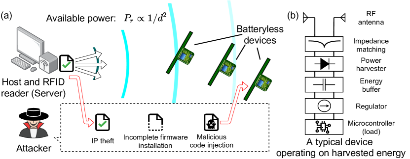
The recent Stork [aantjes2017fast] protocol addressed the challenging problem of fast wireless firmware updates to multiple CRFID devices. But, as illustrated in Fig. 1, Stork allows any party, authorized or not, armed with a simple RFID reader to: i) mount malicious code injection attacks; ii) attempt to spoof the acknowledgment signal of a successful update to fool the Server; and iii) steal intellectual property (IP) by simply eavesdropping on the over-the-air communication channel. Although a recent protocol [su2019secucode] addressed the problem of malicious code injection attacks where by a single CRFID device is updated in turn, it neither supports simultaneous updates to many devices nor protects firmware IP and lacks a mechanism to validate the installation of code on a device.
Why Secure Wireless Firmware Update is Challenging?
Constructing a secure wireless firmware update mechanism for ultra-low power and batteryless devices is non-trivial; designing a secure method is challenging. We elaborate on the challenges below.
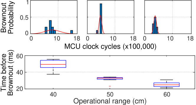
Limited and indeterminate powering. Energy-harvesting systems operate intermittently, only when energy is available from the environment. To operate, a device gradually buffers energy into a storage element (capacitor). Once sufficient energy is accumulated, the device begins operations. However, energy depletes more rapidly (e.g. milliseconds) during an operation compared to energy accumulation/charging (e.g. seconds). Further, energy accumulation in RF energy harvesting is sacrificed in backscatter communication links since a portion of the incident energy is reflected back during communications. Therefore, power failures are common and occur in millisecond time scales [tan2016wisent, aantjes2017fast, dinu2019sia] as experimentally validated in Fig. 2.
Timing of power loss events across devices are ad-hoc. For example, harvested energy varies under differing distances; therefore, a computation task may only execute partially before power failure and it is hard to predict when it will occur.
Further, saving and subsequently retrieving state at code execution checkpoints for a long-run application via an intermittent execution model [maeng2017alpaca] is not only: i) costly in terms of computations and energy [wu2018r]—saving state in non-volatile memories such as Flash or Electrically Erasable Programmable Read-Only Memory (EEPROM) consumes more energy than static RAM (SRAM) whilst reading state from Ferroelectric Random Access Memory (FRAM) consumes more energy than writing as we demonstrate in Fig. 5; but also: ii) renders a device in a vulnerable state for an attacker to exploit when checkpoint state is stored on an off-chip memory, due to the lack of internal MCU memory, where non-invasive contact probes can be used to readout contents when the memory bus used is easily accessible [krishnan2018exploiting]. For example, common memory readout ports such as the I2C (Inter-Integrated Circuit) bus used by a microcontroller for connecting to external memory devices are often exposed on the top layer of a printed circuit board (PCB). Hence, the content stored in an off-chip NVM can be easily read out using contact probes without any damage to the hardware [su2022leaving].
These issues make the execution of long-run security algorithms, such as Elliptic Curve Diffie-Hellman (ECDH)111We are aware of optimized public key exchange implementations such as ECDH and Ring-LWE [liu2015efficient, liu2015efficientches]; however, they are impractical for passively powered resource-constrained devices. For example, ECDH [liu2015efficient] with Curve25519 still requires 4.88 million clock cycles on a MSP430 MCU. In contrast, there are a very limited number of clock cycles available from harvested-energy before energy depletion [su2019secucode, tan2016wisent]—e.g. 400,000 clock cycles expected even at close proximity of 50 cm from an energy source, see Fig. 2—and there is very limited time available for computations where a CRFID must reply before strict air interface protocol time-outs are breached. key exchange, difficult to deploy securely.
Consequently, power must be carefully managed to avoid power loss and leaving the device in a potentially vulnerable state; and, we must seek computationally efficient security schemes.
Unavailability of hardware security support. Highly resource-constraint devices lack hardware security support. Thus, security features, including a trusted execution environment (TEE)—for example, ARM Trustzone [brasser2019sanctuary]—and dedicated memory to explicitly maintain the secrecy of a long term secret keys, as in [frassetto2018imix], are unavailable.
Constrained air interface protocols. The widely used wireless protocol for Ultra High Frequency (UHF) RFID communication only provides insecure unicast communication links and supports no broadcast features or device-to-device communication possible in mesh networking typical of wireless sensor networks.
Unavailability of supervisory control from an operating system. Unlike wireless sensor network nodes, severely resource limited systems, such as CRFID, do not operate under the supervisory control of an operating system to provide security or installation support for a secure dissemination scheme.
1.1 Our Study
We consider the problem of secure and simultaneous code dissemination to multiple RF-powered CRFID devices operating under constrained protocols, device capability, and extreme on-device resource limitations—computing power, memory, and energy.
The scheme we developed overcomes the unique challenges, protects the firmware IP during the dissemination process, prevents malicious code injection attacks and enables remote attestation of code installation. More specifically, we address the following security threats:
-
•
Malicious code injection: code alteration, loading unauthorized code, loading code onto an unauthorized device, and code downgrading.
-
•
Incomplete firmware installation
-
•
IP theft: reverse engineering from plaintext binaries.
Consequently, we fulfil the urgent and unmet security needs in the existing state-of-the-art multiple CRFID wireless dissemination protocol—Stork [aantjes2017fast].
1.2 Our Contributions and Results
Contribution 1 (Section 2)—Wisecr is the first secure and simultaneous (fast) firmware dissemination scheme to multiple batteryless CRFID devices. Wisecr provides three security functions for secure and fast updates: i) preventing malicious code injection attacks; ii) IP theft; and iii) attestation of code installation. Wisecr achieves rapid updates by supporting simultaneous update to multiple CRFID devices through a secure broadcasting of firmware over a standard non-secure unicast air interface protocol
Contribution 2 (Section 3 & LABEL:sec:exp-evals)—A holistic design trajectory, from a formal secure scheme design to an end-to-end implementation requiring only limited on-device resources. Ultra-low power operating conditions and on-device resource limitations demand both a secure and an efficient scheme. First, we built an efficient broadcast session key exchange exploiting commonly available hardware acceleration for crypto on microcontroller units (MCUs).
Second, to avoid power loss and thus achieve uninterrupted execution of a firmware update session, we propose new methods: i) adaptive control of the execution model of devices using RF powering channel state information collected and reported by field deployed devices; ii) reducing disruptions to broadcast data synchronization across multiple devices by introducing the concept of a pilot tag selection from participating devices in the update scheme to drive the protocol. These methods avoid the need for costly, secure checkpointing methods and leaving a device in a vulnerable state during power loss.
Third, in the absence of an operating system, we develop an immutable bootloader to: i) supervise the control flow of the secure firmware update process; ii) minimize the occurrence of power loss during an update session whilst abandoning a session in case an unpreventable power loss still occurs; and iii) manage the secure storage of secrets by exploiting commonly available on-chip memory protection units (MPUs) to realize an immutable, bootloader-only accessible, secrets.
Contribution 3 (Section LABEL:sec:exp-evals and Appendix LABEL:apd:Detailed-protocol)—ISO Standards compliant end-to-end Wisecr implementation. We develop Wisecr from specification, component design to architecture on the device, and implementation. We evaluate Wisecr extensively, including comparisons with current non-secure methods, and validate our scheme by an end-to-end implementation. Wisecr is a standard compliant secure firmware broadcast mechanism with a demonstrable implementation using the widely adopted air interface protocol—ISO-18000-63 protocol albeit the protocol’s lack of support for broadcasting or multi-casting—and using commodity devices from vendors. Hence, the Wisecr scheme can be adopted in currently deployed systems. We demonstrate the firmware dissemination process here https://youtu.be/GgDHPJi3A5U.
Contribution 4—Open source code release. The tool sets and end-to-end implementation is open-sourced on GitHub: https://github.com/AdelaideAuto-IDLab/Wisecr.
Paper Organization. Section 2 presents the threat model, security requirements and Wisecr design; Section 3 details how the demanding security requirements are met under challenging settings; Section LABEL:sec:exp-evals discusses our end-to-end implementation, followed by performance and security evaluations; Section LABEL:sec:relatedwork discusses related work with which Wisecr is compared. Section LABEL:sec:conclusion concludes this work.
2 Wisecr Design
In this section, we describe the threat model including a summary of notations in Table I, followed by details of Wisecr design, and then proceed to identify the minimal hardware security requirements needed to implement the scheme.
| Server is a single entity consisting of a host computer and a networked RFID reader. | |
| Tokens is a set of individual (CRFID) devices . | |
| DB | Server’s database, where each element is a three-tuple describing each CRFID token: i) the unique and immutable identification number ; ii) the device specific secret key ; and iii) a flag denoting a device requiring an update . |
| firmware | The new firmware binary for the update. |
| The block of the firmware. | |
| nver | The new version number (a monotonically increasing ordinal number with a one-to-one correspondence with each updated firmware). |
| ver | A token’s current version number. |
| The broadcast session key. | |
| The MAC tag computed by the Server. | |
| , | Attestation challenge and response, respectively. |
| An apostrophe denotes a value computed by a different entity, e.g., the MAC tag computed by a Token. | |
| A subscript denotes a specific entity, e.g., is the device key of the Token. | |
| Encrypted data, e.g. denotes the encrypted session key sk, with the token’s key . | |
| RNG() | A cryptographically secure random number generator. |
| SKP.Enc() | Symmetric Key Primitive encryption function described by . Here, the plaintext is encrypted with the to produce the ciphertext . |
| SKP.Dec() | Symmetric Key Primitive decryption function where . |
| MAC() | Message Authentication Code function. By appending an authentication tag s to the message m, where , a message authentication code (MAC) function can verify the integrity and authenticity of the message by using the symmetric key k. |
| SNIFF() | The voltage established by the power harvester within a fixed time from boot-up at token , is measured by SNIFF() described by . |
| PAM() | Family of functions employed by the Power Aware Execution mode of operation proposed for the token to mitigate power-loss (brown-out) events. |
| Query | We denote EPC Gen2 commands using typewriter fonts. |
2.1 Threat Model
Communication with an RFID device operating in the UHF range is governed by the widely adopted ISO-18000-63:2015—also known as the EPCglobal Class 1 Generation 2 version 2 (C1G2v2)—air interface protocol or simply the EPC Gen2.
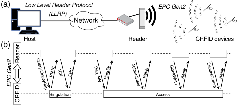
Fig. 3 illustrates the communication channels in a networked RFID system. The RFID reader resides at the edge of the network and is typically connected to multiple antennas to power and communicate with RFID or CRFID devices energized by the antennas. The reader network interface is accessed by using a Low-Level Reader Protocol (LLRP) from a host machine. Communication with an RFID device operating in the UHF range is through the EPC Gen2 protocol.
Our focus is on the insecure communication channel between the RFID reader connected antenna and the CRFID transponder or token . Hence, we assume that the communication between a host and a reader is secured using standard cryptographic mechanisms [jin2017secure]. Therefore, a host computer and a reader are considered as a single entity, the Server, denoted as (a detailed execution of an EPC Gen2 protocol session to singulate a single CRFID device from all visible devices in the field can be found in [tan2016wisent, aantjes2017fast]).
We assume a CRFID device can meet the pragmatic hardware security requirements, detailed in Section 2.3. Further, after device provisioning, the wired interface for programming is disabled—using a common technique adopted to secure resource-constrained microcontroller based devices [dinu2019sia, su2019secucode]. Subsequently, both the trusted party and adversary must use the wireless interface for installing new firmware on a token.
Building upon relevant adversary models related to wireless firmware update for low-end embedded devices [kohnhauser2016secure, feng2017secure], we assume an adversary has full control over the communication channel between the Server and the tokens . Hence, the adversary can eavesdrop, manipulate, record and replay all messages sent between the Server and the tokens . This type of attacker is referred to as an input/output attacker [piessens2016software].
We assume the firmware (application), potentially provided by a third party in the form of a stripped binary, may contain vulnerabilities or software bugs that can cause the program to deviate from the specified behavior with potential consequences being corruption of the bootloader and/or the non-volatile memory (NVM) contents. Such an occurrence is possible when firmware is frequently written in unsafe languages such as C or C++ [sammler2021refinedc, levy2017multiprogramming]. Hence, the firmware (application) cannot be trusted. In this context, similar to [kohnhauser2016secure, feng2017secure], we also assume that the adversary cannot bypass any of the memory hardware protections (detailed in Section 2.3) and an adversary cannot mount invasive physical attacks to extract the on-chip non-volatile memory contents. Such an assumption is practical, especially in deeply embedded applications such as pacemaker control [tan2016wisent] where wireless update is the only practical mechanism by which to alter the firmware and physical access is extremely difficult.
As in [aysu2015end], we also assume the adversary cannot mount implementation attacks against the CRFID, or gain internal variables in registers, for example, using invasive attacks and side-channel analysis. We do not consider Denial of Service (DoS) attacks because it appears to be impossible to defend against such an attacker, for example, that disrupts or jams the wireless communication medium in practice [kohnhauser2016secure].
2.2 Wisecr Update Scheme
Wisecr enables the ability to securely distribute and update the firmware of multiple CRFID tokens, simultaneously. Given that a Server must communicate with an RFID device using EPC Gen2, Wisecr is compatible with EPC Gen2 by design. Generally, our scheme can be implemented after the execution of the anti-collision algorithm in the media access control layer of the EPC Gen2 protocol, where a reader must first singulate a CRFID device and obtain a handle, , to address and communicate with each specific device. After singulating a device, the server can employ commands such as: BlockWrite, Authenticate, SecureComm and TagPrivilege specified in the EPC Gen2 access command set [epcglobal2015inc], to implement the Wisecr scheme. We describe the update scheme in Fig. 4 and defer the details of our scheme implemented over the EPC Gen2 protocol to the Appendix LABEL:apd:Detailed-protocol.
As described in Table I, the Server maintains a database DB of provisioned tokens, issues the new firmware and the corresponding version number ().
Each token has a secure storage area provisioned with: i) an , the immutable identification number; ii) , the device specific secret key stored in NVM that is read-only accessible by the immutable bootloader. The assigned to different devices are assumed to be independent and identically distributed (i.i.d.); iii) , the token’s current firmware version number. The secure storage area is only accessible by the trusted and immutable bootloader provisioned on the device; this region is inaccessible to the firmware (application) and therefore cannot be modified by it.
We describe a dissemination session in four stages: i) Prelude; ii) Security Association; iii) Secure Broadcast; and iv) Validation. An update can be extended with an optional, v) Remote Attestation to verify the firmware installation.
STAGE 1: Prelude (Offline). In this stage, the Server undertakes setup tasks. The Server uses RNG() to generate a broadcast session key ().
The new firmware is divided into segments—or block; each block is encrypted as SKP.Encsk(), where denotes the encrypted firmware block . The division of firmware is necessary as the narrow band communication channel and the EPC Gen2 protocol does not allow arbitrary size payloads to be transmitted to a token.
STAGE 2: Security Association. In this stage, the Server distributes the broadcast session key () to all tokens and builds a secure broadcast channel over which to simultaneously distribute the firmware to multiple tokens.
More specifically, each token in the energizing field of the Server responds with , Vti and . The token will not be included in the following update session if: i) the of the responding token is not in Server’s DB; or ii) the token is not scheduled for an update ( False). For tokens selected for an update, the Server computes a MAC tag MAC(). In practice, we cannot assume that each token is executing the same version of the firmware, therefore a token specific MAC tag is generated over the device specific key whilst the firmware is encrypted with the broadcast session key.
The Server establishes a shared session key with each token by sending , where SKP.Enc and is specific to the token, and . The and are transmitted to each token . Each token decrypts the broadcast session key SKP.Dec—thus, all tokens selected for an update now possess the session key.
Notably, as detailed in Section 3.2.2, each token measures its powering channel state or its ability to harvest energy by measuring the voltage established by the power harvester within a fixed time from boot-up, as to transmit to the Server. There are two important reasons for measuring . First, to facilitate the power aware execution model (PAM) employed to mitigate power-loss at a given token. The Server uses the reported to control the execution model of the token. Specifically, the reported is used by the Server to determine the length of time that a token dwells in low power mode (LPM) and active mode when executing computationally intensive tasks in the Secure Broadcast and Validation stages; here, the server determines . Second, the Server uses the reported to realize the Pilot-Observer Mode of operation where one token is elected based on its , termed the Pilot, to control the flow in the Secure Broadcast stage by responding to server commands as detailed in Stage 3.
STAGE 3: Secure Broadcast. In this stage, the encrypted firmware blocks are broadcasted; and each token stores the new encrypted firmware blocks in its application memory region (Segment defined in Section 3.1). Once the broadcast is completed, each token starts firmware decryption and validation. The is decrypted using the session key as .
To realize a secure and power efficient logical broadcast channel under severely energy constrained settings, we use the Pilot-Observer mode. Herein, all tokens, except the Pilot token elected by the Server, enters into an observer mode. The tokens in the observer mode silently listen and store encrypted data disseminated by the server; the Pilot token performs the same operation whilst responding to the server commands. We employ two techniques within the Pilot-Observer Mode to mitigate power-loss and to achieve a secure broadcast to tokens: i) disabling energy consuming communication command reply from observers; and ii) the concept of electing a Pilot CRFID device to drive the update session as detailed in Section 3.2.2.
Notably, the techniques described in Stage 2 and 3 form the foundation for the uninterrupted execution of the bootloader to ensure security and enhance the performance of the firmware dissemination under potential power-loss events.
STAGE 4: Validation. In this stage, firmware is validated before installation. More precisely, a token specific MAC tag is computed by each token . If the received MAC tag matches the device computed , the integrity of the firmware established and the issuing Server is authenticated by the token. Subsequently, the new firmware is updated and the new version number is stored as . Otherwise, the firmware is discarded and the session is aborted. Notably, the EPC Gen2 protocol provides a reliable transfer feature. Each broadcast payload is protected by a 16-bit Cyclic Redundancy Check (CRC-16) error detection method. Hence, the notification of a CRC failure to the Server results in the automatic re-transmission of the packet by the Server. Therefore, a MAC tag mismatch is more likely to be adversarial and discarding the firmware is a prudent action. At stage completion, each token switches from the observer or Pilot to the normal mode of operation after a software reset (reboot). Subsequently, all the temporary information such as session key and the token specific MAC tag in volatile memory will be erased.
Once the firmware is installed, the Server is acknowledged with the status of each participating token in the session. This is achieved by performing an EPC Gen2 handshake after a reboot of the tokens, and comparing the version number reported from each token specified by to the new firmware version number expected from the token. If the is up-to-date, the Server is acknowledged that the token has been successfully updated.
Remark. It is theoretically possible to include a MAC tag in the acknowledgment message at the end of the Validation stage to authenticate the acknowledgment. But the implementation of this in practice is difficult under constrained protocols and limited resources typical of intermittently powered devices. This is indeed the case with the EPC Gen2 air interface protocol and CRFID devices we employed. We discuss specific reasons in Appendix LABEL:apd:Detailed-protocol where we detail implementation of the Wisecr Update Scheme over the EPC Gen2 air interface protocol.
STAGE 5 (Optional): Remote Attestation.
The Server can elect to verify the firmware installation on a token by performing a remote attestation; a mechanism for the Server to verify the complete and correct software installation on a token. Considering the highly resource limited tokens, we propose a lightweight challenge response based mechanism re-using the MAC() function developed for Wisecr. The server sends a randomly generated challenge and evaluates the corresponding response to validate the installation. We provision a new session key to enable the remote attestation to proceed independent of the previous stages, whilst avoiding the derivation of a key on device to reduce the overhead of the attestation routine.
We propose two modes of attestation; a fast mode and an elaborate mode to trade-off veracity of the verification against computational and power costs. The fast mode only examines the token serial number () and the version number (). While the elaborate mode traverses over an entire memory segment. The elaborate mode is relatively more time consuming but allows the direct verification of the code installed on the target token .
We illustrate (in Fig. 4) and demonstrate (in Section LABEL:sec:performance) the elaborate mode (more veracious and computationally intensive) where response attests the application memory segment containing the installed firmware. In contrast, the fast method computes the response as .
2.3 Token Security Requirements and Functional Blocks
Our design is intentionally minimal and requires the following security blocks.
- Immutable Bootloader
-
(Section 3.1) We require a static NVM sector that is write-protected to store the executable bootloader image to ensure the bootloader can be trusted post deployment where, for example, firmware (application) code vulnerabilities or software bugs do not lead to the corruption of the bootloader and the integrity of the bootloader can be maintained.
- Secure Storage
-
(Section 3.1) To store a device specific secret, e.g., , we require an NVM sector read-only accessible by the immutable bootloader in sector . This ensures the integrity and security of non-volatile secrets post deployment since the firmware (application) code cannot be trusted, for example, due to potential vulnerabilities or software bugs that can lead to the corruption of non-volatile memory contents).
- Uninterruptible Bootloader Execution
-
(Section 3.2) During the execution of the bootloader stored in sector , execution cannot be interrupted until the control flow is intentionally released by the bootloader.
- Efficient Security Primitives
-
(Section 3.3) The update scheme requires: i) a symmetric key primitive; and ii) a keyed hash primitive for the message authentication code that are both computationally and power efficient.
In Section 3 we discuss how the associated functional blocks are engineered on typical RF-powered devices built with ultra-low power commodity MCUs.
3 On-device Security Function Engineering
To provide comprehensive evaluations and demonstrations, we selected the WISP5.1LRG [Wisp5] CRFID device with an open-hardware and software implementation for our token . This CRFID device uses the ultra-low power MCU MSP430FR5969 from Texas Instruments. Consequently, for a more concrete discussion, we will refer to the WISP5.1LRG CRFID and the MSP430FR5969 MCU in the following.
3.1 Immutable Bootloader & Secure Storage
For resource limited MCUs, several mechanisms—detailed in the Appendix LABEL:apd:memory_management_compare—exists for implementing secure storage: i) Isolated segments; ii) Volatile keys; iii) Execute only memory; and iv) Runtime access protections. We opt for achieving secure storage and bootloader immutability using Runtime Access Protection by exploiting the MCU’s memory protection unit (MPU), which offers flexibility to the bootloader. In particular, the MPU allows read/write/execute permissions to be defined individually for memory segments at power-up—prior to any firmware (application) code execution. Wisecr requires the following segment permissions to be defined by the bootloader to prevent their subsequent modifications through application code by locking the MPU:
- Segment
-
is used as the secure storage area. During application execution, any access (reading/writing) to this segment results in an access violation, causing the device to restart in the bootloader.
- Segment
-
contains the bootloader, device interrupt vector table (IVT), shared code (e.g., EPC Gen2 implementation). During application execution, writing to this segment results in an access violation.
- Segment
-
covers the remaining memory, and is used for application IVT, code (firmware) and data.
3.2 Uninterruptible Bootloader Execution
The execution or control flow of the bootloader on the token must be uninterruptible by application code and power-loss events to meet our security objectives but dealing with brownout induced power-loss events is more challenging. Power loss leaves devices in vulnerable states for attackers to exploit; therefore, we focus on innovative, pragmatic and low-overhead power-loss prevention methods. Our approach deliberately mitigates the chances of power-loss. In case a rare power-loss still occurs, the token will discard all state—including security parameters such as the broadcast session key; subsequently, the Server will re-attempt to update the firmware by re-commencing a fresh update session with this token. We detail our solution below.
3.2.1 Managing Application Layer Interruptions
The bootloader must be uninterruptible (by application code) for security considerations. For instance, the application code—due to an unintentional software bug or otherwise—could interrupt the bootloader while the device key is in a CPU register, so that the application code (exploited by an attacker) can copy the device key to a location under its control, or completely subvert access protections by overriding the MPU register before it is locked.
Recall, the memory segment (see Section 3.1) includes the memory region containing the IVT. This ensures that only the bootloader can modify the IVT. Since the IVT is under the bootloader’s control, we can ensure that any non-maskable interrupt is unable to be directly configured by the application code, whereas all other interrupts are disabled during bootloader execution. Consequently, the interrupt configuration cannot be mutated by application code.
3.2.2 Managing Power-Loss Interruptions
Frequent and inevitable power loss during the bootloader execution will not only interrupt the execution, degrading code dissemination performance but also compromise security. Although intermittent computing techniques relying on saving and retrieving state at check-points from NVM—such as Flash or EPPROM—is possible, these methods impose additional energy consumption and introduce security vulnerabilities revealed recently [krishnan2018exploiting].
Confronted with the complexity of designing and implementing an end-to-end scheme under extreme resource limitations, we propose an on-device Power Aware execution Model (PAM) to: i) avoid the overhead of intermittent computing techniques; and ii) enhance security without saving check-points to insecure NVM.
We observe that only a limited number of clock cycles are available for computations per charge and discharge cycle (Intermittent Power Cycle or IPC) of a power harvester, as illustrated via comprehensive measurements in Fig. 2. Further, the rate of energy consumption/depletion is faster than energy harvesting. We recognize that there are three main sources of power-loss: i) (CPU) energy required for function computation exceeding the energy supply capability from the harvester; ii) (FRAM.R/W) memory read/write access such as in executing Blockwrite commands; and iii) (RFID) power harvesting disruptions from communications—especially for backscattering data in response to EPC Gen2 commands.
To understand the severity of these four causes, we measure the maximum time duration before brownout/power-loss versus the harvested power level for each task—CPU, FRAM.R, FRAM.W and RFID. In the absence of a controlled RF environment (i.e., anechoic chamber), it is extremely difficult to maintain the same multipath reflection pattern. Especially when changing the distance between the radiating reader antenna and an instrumented CRFID device considering the multipath interference created by the probes, cables, and the nearby oscilloscope and researcher to monitor the device’s internal state. To minimize the difficulty of conducting the experiments, we place the CRFID device at a fixed distance (20 cm) whilst keeping all of the equipment at fixed positions, and adjust the transmit power of the RFID reader through the software interface. According to the free-space path loss equation [friis1946free], adjusting the transmit power of the RFID reader or changing the distance can be used to vary the available power at the CRFID device. We describe the detailed experimental settings in Appendix LABEL:apd:power_based_exp_setup. For experiments without the requirement for monitoring the device’s internal state, we still employ distance-based measurements as in previous studies [aantjes2017fast, wu2018r, su2019secucode].
The results are detailed in Fig. 5. For a transmit power greater than 800 mW, the CRFID transponder continuously operates without power failure within 100 seconds. If the reader transmit power is below 800 mW, the average operating time of the RFID task drops as the power level decreases. This is because the RFID communication process invokes shorting the antenna, during which the energy harvesting is interrupted. Notably, different from Flash memory, reading data from FRAM (FRAM.R) consumes more power than writing to it (FRAM.W) as a consequence of the destructive read and the compulsory write-back [thanigai2014msp430]. Consequently, we developed:
-
•
The Pilot-Observer Mode to reduce the occurrence of RFID tasks by enabling observing devices to listen to broadcast packets in silence whilst electing a single Pilot token to respond to the Server.
-
•
The Power Aware Execution Model (PAM) to ensure memory access (FRAM tasks) and intensive computational blocks of the security protocol (CPU tasks) do not exceed the powering capability of the device.
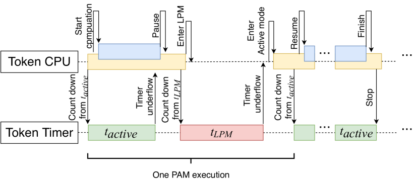
Power Aware Execution Model (PAM). The execution mode enables a token to dynamically switch between active power mode and lower power mode (LPM)—LPM preserves (SRAM) state and avoids power-loss while executing a task. PAM is illustrated in Fig. 6. In active power mode, the token executes computations, and switches to LPM before power-loss to accumulate energy; subsequently, the token is awoken to active power mode to continue the previous computation after a period of .
Our PAM model builds upon [buettner2011dewdrop, su2019secucode] in that, these are designed for execution scheduling to prevent power-loss from brownouts. Compared to [su2019secucode], we consider dynamic scheduling of tasks and in contrast to [buettner2011dewdrop] sampling of the harvester voltage (only possible in specific devices) within the application code, we consider dynamic scheduling determined by the more resourceful Server using a single voltage measurement reported by a token (see Appendix LABEL:apd:PAM-methods for detailed comparison). We outline the means of achieving our PAM model on a token below.
During the Security Association stage shown in Fig. 4, a token measures and reports the voltage to the Server. The measurement indicates energy that can be harvested by token under the settings of the current firmware update session. According to , the Server determines the active time period and LPM time period for each CRFID device (detailed development of a model to estimate and from is in Appendix LABEL:apd:paem). Consequently, each CRFID device’s execution model is configured by the Server with device specific LPM and active periods at run-time. Hence, an adaptive execution model customized to the available power that could be harvested by each CRFID device is realized. Notably, this execution scheduling task is outsourced to the resourceful Server.
In this context, we assume the distances between the antenna and target CRFID devices are relatively constant during the short duration of a firmware update. Firmware updates are generally a maintenance activity where CRFID integrated components are less likely to be mobile to ease maintenance, such as during the scheduled maintenance of an automated production line [fischer2017advancements]; night time updates in smart buildings when people are less likely to be present and facilities are inoperative [elmangoush2015application]; or the pre-flight maintenance or inspection of aircraft parts while parked on an apron [yang2018rfid]. Further, it is desirable to maintain a stable powering channel in practice by ensuring a consistent distance during the maintenance or patching of devices for a short period. This is a more reasonable proposition than the wired programming of each device. Hence, the relatively fixed distance is a reasonable assumption in practice. Notably, given the challenging nature of the problem, previous non-secure firmware update methods, such as [wu2018r] and Stork [aantjes2017fast], were evaluated under the same assumption.
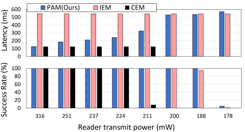
PAM Experimental Validation. To understand the effectiveness of our PAM method to reduce the impact of brownout, we execute a computation intensive module, MAC() using PAM, at power-up on a CRFID. We employ a few lines of code to toggle GPIO pins to indicate the successful completion of a routine. Notably, it is difficult to track a device’s internal state without a debug tool attached to the device; however, if the debug interface is in use, it will either interfere with powering, or affect the timing by involving additional Joint Test Action Group (JTAG) service code. We measure the time taken to complete the MAC() execution (latency) and success rate (success over 10 repeated attempts under wireless powering conditions) with digital storage oscilloscope connected to GPIO pins indicating a successful execution before power loss. We compute a MAC over a 1,536-Byte randomly generated message to test the effectiveness of PAM in preventing a power loss event due to brown-out and compare performance with the execution method—denoted IEM—of a fixed LPM state (30 ms) programmatically encoded during the device provisioning phase as in [su2019secucode].
The results in Fig. 7 show the effectiveness of PAM to mitigate the interruptions from power loss. This is evident when the success rate results without PAM—using the continuous execution model (CEM)—is compared with those of PAM at decreasing operating power levels. However, as expected, we can also observe that the dynamically adjusted execution model parameters ( and ) of PAM at decreasing power levels to prevent power loss events and increase latency or the time to complete the routine. When PAM is compared with IEM, the dynamically adjusted execution model parameters allow PAM to demonstrate an improved capability to manage interruptions from power-loss at poor powering conditions; this is demonstrated by the higher success rates when the reader transmit power is at 188 mW and 178 mW. Since IEM encodes operating settings programmatically during the device provisioning phase [su2019secucode], we can observe increased latency at better powering conditions when compared to PAM which allows a completion time similar to that obtained from CEM when power is ample. Thus, PAM provides a suitable compromise between latency and successful completion of a task at different powering conditions.
Notably, the RFID media access control (MAC) layer on a CRFID device is implemented in software as assembly code and executed at specific clock speeds to ensure strict signal timing requirements in the EPC Gen2 air interface protocol. Additionally, protocol message timing requirements places strict limits on waiting periods for devices responses. Hence, we do not consider the direct control of the execution mode during communication sessions for managing power consumption and instead rely on the Pilot-Observer mode method we investigate next.
| Clock Cycles11footnotemark: 1 | Memory Usage (Bytes) | Operation | ||
| ROM | RAM | |||
| \addstackgapPilot token receiving | 23,082 | 12 | 2 | \addstackgap apply decoding, prepare reply (e.g., compute CRC) |
| \addstackgapPilot token replying | 1,131 | 0 | 0 | communication (backscattering) |
| \addstackgapObserver token receiving | 22,002 | 12 | 2 | apply decoding |
-
• 11footnotemark: 1
Numbers are collected using a JTAG debugger where the reported values are averages over 100 repeated measurements. We provide a detailed discussion of the experiments and analysis process in Appendix LABEL:apd:overhead_receiving_broadcast_packets.
Pilot-Observer Mode.
.
We observed and also confirmed in Fig. 5 that the task of responding to communication commands will likely cause power loss. During the Secure Broadcast stage shown in Fig. 4, communication is dominated by repeated SecureComm commands with payloads of encrypted firmware and the data flow is uni-directional. Intuitively, we can disable responses from all the tokens to save energy. However, the SecureComm command under EPC Gen2 requires a reply (ACK) from the token to serve as an acknowledgment [epcglobal2015inc]. An absent ACK within 20 ms will cause a protocol timeout and execution failure.
To address the issue, we propose the pilot-observer mode inspired by the method in Stork [aantjes2017fast]. A critical and distinguishing feature of our approach is the intelligent election of a pilot token from all tokens to be updated—we defer to Appendix LABEL:apd:ObsvsPilot for a more detailed discussion on the differences. As illustrated in Fig. 8(a), our approach places all in-field tokens to be updated into an observer mode except one token elected by the Server to drive the EPC Gen2 protocol—this device is termed the Pilot token. By doing so, observer tokens process all commands such as SecureComm—ignoring the handle designating the target device for the command—whilst remaining silent or muting replies to all commands whilst in the observer mode. Muting replies significantly reduce energy consumption and disruption to power harvesting of the tokens.
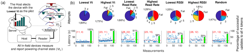
We propose electing the token with the lowest reported Vt as the pilot based on the observation: measuring powering channel state from the token, obtained from , is the most reliable measure of power available to a given device (see the discussion in Appendix LABEL:apd:paem).
We recognize that it is very difficult to implement an explicit synchronization method to ensure the observer tokens stay synchronized with the pilot token in the secure broadcast update session. This is due to the level of complexity and overhead that an explicit method would bring and the consequence of such an overhead would be the increased occurrence of failures of a secure broadcast update session due to the additional task demands on tokens—we discuss the problem further in LABEL:sec:conclusion. Although synchronization between the pilot and observer tokens are not explicit, the Pilot-Observer method implicitly enforces a degree of synchronicity. The selected pilot token—tasked with responding to the Host commands during the broadcast—has to spend more time than observer tokens to prepare the uplink packet and send a reply (ACK) to the Host (RFID reader) to meet the EPC Gen2 specification requirements as summarized in Table II; hence the update process is controlled by the slowest token. Further, since we elect the token with the lowest powering condition as the pilot, the update is controlled by the most energy-starved token. This strategy leads to other tokens having higher levels of available power and extra time to successfully process the broadcasted firmware and remain synchronized with the update process. Hence, if the pilot succeeds, observers are expected to succeed.
Validation of Pilot Election Method. To demonstrate the effectiveness of our pilot token election method, we considered seven different pilot token selection methods based on token based estimations of available power and indirect methods of estimating the power available to a token by the server: 1) Lowest : this implies the pilot is selected based on the most conservative energy availability at token; 2) Highest : the pilot has to reply to commands, hence we may expect higher power availability to prevent the failure of a broadcast session due to brownout at the pilot; 3) Lowest Read Rate: a slow pilot allows observers to gather more energy during the broadcast and remain synchronized with the protocol to prevent failure of the observer tokens; 4) Highest Read Rate: a faster pilot could reduce latency; 5) Lowest Received Signal Strength Indicator (RSSI): successful communication over the poorest channel may ensure all observers are on a better channel (RSSI acts as an indirect measure of the powering channel at a token); 6) Highest RSSI: prevent pilot failure due to a potentially poor powering channel at the pilot token; and 7) Random selection: monkey beats man on stock picks.
We have extensively evaluated and compared all of the above seven pilot token selection methods. The experiment is conducted by placing 4 CRFID tokens at 20 cm, 30 cm, 40 cm and 50 cm above an reader antenna; each CRFID is placed in alignment with the four edges of the antenna (See LABEL:fig:vsSecuCode.(d)). We repeated the code dissemination process 100 times at each distance test, for each of the 7 different pilot selection methods. We recorded two measures: i) latency (seconds); and ii) number of times the broadcast attempt updated all of the 4 in-field devices.As illustrated in Fig. 8.(b), at 40 cm where the power conditions are more critical at a token, the selected pilot token with the lowest token voltage (Vt) shows an enormous advantage, in terms of both latency and attempt number. Overall, our proposed approach (electing the lowest Vt) ensures that most observer tokens are able to correctly obtain and validate the firmware in a given broadcast session on the first attempt in the critical powering regions of operation (we provide a theoretical justification in Appendix LABEL:apd:paem).
We also evaluated the reduction in power consumption achieved from computational tasks, in addition to eliminating the communication task. While we provide a detailed discussion of the experiments and analysis process in Appendix LABEL:apd:overhead_receiving_broadcast_packets, we summarize our experimental results in Table II. The measurements show that the observer tokens, compared to the pilot token, consumes 2,211 less clock cycles per firmware packet from the Host. This is a reduction of 9.13% to process each firmware packet sent from the Host.
Summary. Our pilot-election based method effectively reduces the chance of power failure as well as de-synchronization of the observer tokens during a firmware broadcast session. Our approach is able to ensure that more of the observer tokens are able to correctly obtain and validate the firmware during a single broadcast sessions.
3.3 Efficient Security Primitives
Wisecr requires two cryptogrpahic primitives: i) symmetric key primitive SKP(); and ii) a keyed hash primitive for the message authentication code MAC(). When selecting corresponding primitives in the following, two key factors are necessary to consider:
-
1.
Computational cost: The CPU clock cycles required for a primitives quantifies both the computation cost and energy consumption. Therefore, clock cycles required for executing the primitives need to be within energy and computational limits of the energy harvesting device.
-
2.
Memory needs: On-chip memory is limited—only 2 KiB of SRAM on the target MCU—and must be shared with: i) the RFID protocol implementation; and ii) user code.
Symmetric Key Primitives. We fist compare block ciphers via software implementation benchmarks—clock cycle counts and memory usage—on our target microcontroller [buhrow2014block, dinu2015triathlon]. We also considered the increasingly available cryptographic co-processors in microcontrollers: our targeted device uses an MSP430FR5969 microcontroller and embeds an on-chip hardware Advanced Encryption Standard (AES) accelerator (we refer to as HW-AES) [instruments2014msp430fr58xx]. Based on the above selection considerations, HW-AES is confirmed to outperform others. Specifically, HW-AES to encrypt/decrypt a 128-bit block consumes 167/214 clock cycles with a power overhead of A/MHz; therefore we opted for HW-AES for SKP.Dec function implementation on our target device. We configured AES to employ the Cipher-Block Chaining (CBC) mode222We are aware of CBC padding oracle attacks; however, in our implementation, the response an attacker can obtains is to the CMAC failure or success and not the success or failure of the decryption routine. Alternatively, the routines can be changed to employ authenticated encryption in the future, with an increase in overhead. similar hardware AES resources can be found in a variety of microcontrollers, ASIC, FPGA IP core and smart cards. In the absence of HW-AES, a software AES implementation, such as tiny-AES-c can be an alternative.
Message Authentication Code. MACs built upon BLAKE2s-256, BLAKE2s-128, HWAES-GMAC and HWAES-CMAC on our targeted MSP430FR5969 MCU were taken into consideration [su2019secucode]. We selected the 128-bit HWAES-CMAC—Cipher-based Message Authentication Code333The implementation in NIST Special Publication 800-38B, Recommendation for Block Cipher Modes of Operation: the CMAC Mode for Authentication is used here.—based on AES since it yielded the lowest clock cycles per Byte by exploiting the MCU’s AES accelerator (HW-AES).
3.4 Bootloader Control Flow
We can now realize an uninterruptible control flow for an immutable bootloader built upon on the security properties identified and engineered to achieve our Wisecr scheme described in Section 2.2. We describe the bootloader control flow in Fig. 9.
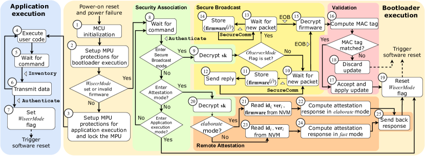
At power-up, he token performs MCU initialization routines, etup MPU protections for bootloader execution and carries out a self-test to determine whether a firmware update is required, or if there is a valid application installed. If no update is required and the user application is valid, he bootloader configures MPU protections for application execution, before handing over control to the application. During the application execution, he user code is executed, hen the token waits for command from the Server , the Server may send an Inventory commands to instruct the token to end back e.g., sensed data, or in setup the WisecrMode flag and trigger a software reset in preparation for an update.
Security Association. Upon a software reset, a set WisecrMode flag directs the token to enter the Security Association stage. ubsequently, the token waits for further instructions from the Server. On reception of an Authenticate command, carrying an encrypted broadcast session key and the MAC tag of the new firmware, he token decrypts with its device key and acquires the session key .
Secure Broadcast. Recall, at this stage, all tokens selected for update will be switched into the observer mode except the pilot token that is set to respond to the Server. The pilot token in state eceives a new chunk of encrypted firmware , and stores it into the specified memory location. he pilot token sends reply to the Server. In for tokens in observer mode, they silently listen to the communication traffic between the Server and the Pilot token without replying. In other words, tokens under observer mode receives the encrypted firmware chunks, tore chunks in memory but ignores unicast handle identifying the target device; this significantly saves observers’ energy from replying as detailed in Section 3.2.2. Once an End of Broadcast (EOB) message is received, all tokens stop waiting for new packets and start firmware decryption
Validation. The token computes a local MAC tag , including the decrypted firmware, and compares it with the received MAC tag The firmware is accepted, applied to update he token, if and are matched, and he WisecrMode flag is reset; otherwise, he firmware is discarded and the update is aborted. Subsequently, each token performs a software reset to execute the new firmware or reinitialize in bootloader mode if the firmware update is unsuccessful.
Remote Attestation. On reception of an Authenticate command with an instruction to perform remote attestation, he token first decrypts the session key and reads