Channel Estimation for Intelligent Reflecting Surface Assisted Backscatter Communication
Abstract
Intelligent reflecting surface (IRS) is a promising technology to improve the performance of backscatter communication systems by smartly reconfiguring the multi-reflection channel. To fully exploit the passive beamforming gain of IRS in backscatter communication, channel state information (CSI) is indispensable but more practically challenging to acquire than conventional IRS-assisted systems, since IRS passively reflects signals over both the forward and backward (backscattering) links between the reader and tag. To address this issue, we propose in this letter a new and efficient channel estimation scheme for the IRS-assisted backscatter communication system. To minimize the mean-square error (MSE) of channel estimation, we formulate and solve an optimization problem by designing the IRS training reflection matrix for channel estimation under the constraints of unit-modulus elements and full rank. Simulation results verify the effectiveness of the proposed channel estimation scheme as compared to other baseline schemes.
Index Terms:
Intelligent reflecting surface, backscatter communication, channel estimation.I Introduction
Intelligent reflecting surface (IRS) has recently emerged as a promising technology to enhance the spectrum and energy efficiency of future wireless systems cost-effectively [1]. Specifically, IRS is able to engineer favourable wireless propagation environment via controlling signal reflection at its large number of passive reflecting elements. This thus has motivated active research recently in applying IRS to existing wireless systems, such as UAV communication, wireless power transfer, millimeter wave communication, mobile edge computing, and backscatter communication [1, 2, 3, 4, 5, 6].
Particularly, for IRS-assisted backscatter communication systems, IRS can be properly deployed to enhance the channel gain over both the forward (transmission) and backward (backscattering) links between the reader and tag, where the reader transmits the carrier signal to the tag, while the tag appends its own information to the received signal and backscatters it to the reader. However, to achieve the enormous passive beamforming gain brought by IRS, channel state information (CSI) is crucial and needs to be acquired, which, however, is more practically challenging than conventional IRS-assisted systems. This is because both the IRS and tag can reflect signals only without sophisticated signal processing capability. Thus, only the composite channel, which is the product of the forward and backward channels, can be estimated at the reader based on the pilot signal sent by itself. In particular, each of the forward/backward channel is the superposition of the reader-tag direct channel and the reader-IRS-tag cascaded channel. This makes the conventional channel estimation schemes for backscatter communication systems without IRS [7] and IRS-assisted communication systems without tag [8, 9, 10, 11, 12] inapplicable, thus motivating the current work to tackle this challenge.
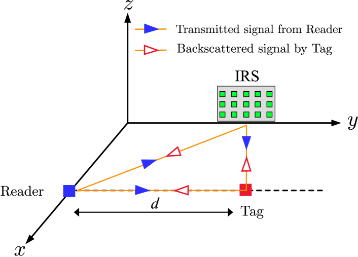
Specifically, we consider in this letter an IRS-assisted monostatic backscatter communication system as illustrated in Fig. 1, where an IRS is employed to assist the communication between a reader and a tag, both equipped with a single antenna. A novel channel estimation scheme is proposed to efficiently estimate both the reader-tag direct channel and reader-IRS-tag reflecting channel, by controlling the IRS training reflections over time. Moreover, the IRS training matrix is optimized to minimize the channel estimation error, for which the optimal solution is derived in closed form. Simulation results verify the effectiveness of the proposed channel estimation scheme as compared to other baseline schemes.
Notations: In this letter, vectors and matrices are denoted by bold-face lower-case and upper-case letters, respectively. For a complex-valued vector , we denote by , , , , and as its -norm, transpose, conjugate transpose, a diagonal matrix with diagonal elements being the corresponding elements in , and the elements from the -th entry to the -th entry of , respectively. Scalar denotes the -th element of a vector . For a square matrix , and denote its trace and inverse, respectively. For any matrix , we denote by , , and as its conjugate transpose, rank, and th element, respectively. denotes an identity matrix with appropriate dimensions. denotes the space of complex-valued matrices. denotes the imaginary unit, i.e., . For a complex-valued scalar , we denote by , , and its absolute value, phase, and complex conjugate, respectively. denotes the cardinality of the set . denotes the statistical expectation. denotes the Kronecker product.
II System Model
As shown in Fig. 1, we consider an IRS-assisted monostatic backscatter communication system, where an IRS composed of subsurfaces is deployed to assist in the communication between a full-duplex (FD) single-antenna reader and a single-antenna tag. Let , , and denote the baseband equivalent channels from the reader to tag, reader to IRS, and IRS to tag, respectively, which are assumed to remain constant within each channel coherence interval. For the IRS, we denote by its reflection vector, where and , with , respectively denote the (common) reflection amplitude and phase shift of all reflecting elements in subsurface . For simplicity, we set (or its maximum value), , to maximize the IRS reflected signal power in both channel training and data transmission.
Let denote the signal sent by the reader with power . As no signal processing is performed at the tag and thus no noise added, the signal received at the tag over both the direct and IRS reflecting links is thus given by
| (1) |
where denotes the cascaded reader-IRS-tag channel. Let denote the portion of signal reflected by the tag, which is simply set as in the sequel without loss of generality. Then, based on channel reciprocity, the received signal at the reader is given by111In practice, a decoupler is usually integrated into the reader to enable the FD operation by suppressing the self-interference caused by the transmitted signal [13].
| (2) |
where denotes the additive white Gaussian (AWGN) noise at the reader with power . For convenience, we normalize the noise power by and thereby assume without loss of generality; thus the symbol can be omitted in (2) in the sequel. We consider a two-phase data transmission protocol, where each channel coherence block of symbols is divided into two phases. During the first channel training phase, the reader consecutively transmits pilot symbols, while the IRS properly sets its training reflections over time to facilitate the channel estimation at the reader. Based on the estimated channel, the reader designs the IRS passive beamforming for data transmission, denoted by , and sends it to the IRS controller via a separate link for it to tune the IRS reflection accordingly for aiding the tag’s backscatter communication over the remaining symbols in the second data transmission phase. From (2) and under the assumption of perfect CSI at the reader, the optimal IRS passive beamforming that maximizes the received signal-to-noise ratio (SNR) at the reader is given by
| (3) |
III Proposed Channel Estimation and Training Design
It is observed from (3) that the optimal IRS passive beamforming design for data transmission requires the CSI of both the reader-tag direct link and the cascaded IRS reflecting link, i.e., and , with totally complex-valued channel coefficients. However, such CSI cannot be obtained by applying the existing IRS channel estimation methods (see e.g., [9, 10, 8]) for the linear channel model with training symbols only, since in (2) is a nonlinear function of and , leading to the issue of sign ambiguity. Specifically, for each training symbol , the corresponding effective channel (assuming for the purpose of illustration) from the reader to tag is given by
| (4) |
where denotes the IRS reflection vector for the -th symbol. Due to the sign ambiguity in (4) for determining , the conventional methods in [9, 10, 8] with time-varying ’s cannot be applied to estimate and in the nonlinear channel model in (2) uniquely.
III-A Proposed Channel Estimation Scheme
We first present two useful lemmas as follows.
Lemma 1
The received signal at the reader in (2) can be equivalently rewritten as
| (5) |
where and .
Proof:
Note that in (5), depends on the IRS training reflection only and is determined by the CSI (i.e., and ) only.
Lemma 2
The optimal IRS passive beamforming for data transmission in (3) can be equivalently rewritten as
| (8) |
where .
Proof:
First, we have . Second, it follows from (5) that and . Combining the above leads to the desired result. ∎
Lemma 2 shows that it is sufficient to acquire the CSI of the first elements of (i.e., and ) for designing the optimal IRS passive beamforming for data transmission. Thus, we propose an efficient channel estimation scheme in the next to estimate and .
Our key idea is by leveraging the phase-rotated IRS training reflections to resolve the sign ambiguity issue. Specifically, the proposed channel estimation scheme consists of sub-blocks. In each sub-block , the reader sends two pilot signals while the IRS sets its training reflections as and its phase-rotated version , with over the two symbols. Let and denote the two received pilot signals in sub-block . Based on (6), we have
| (9) | ||||
| (10) |
where . Let , , and . It then follows that
| (11) |
where is the AWGN noise with (normalized) power . For the received signals over the sub-blocks, by defining ,
| (12) |
, and , we have
| (13) |
where is defined as the effective IRS training reflection matrix over sub-blocks and is the required CSI for the passive beamforming design. Next, by properly designing and (or equivalently and ) such that , the least-square (LS) estimation of can be obtained as
| (14) |
where denotes the channel estimation error in . Note that to ensure , at least sub-blocks and hence equivalently training symbols are required for estimating . According to (14), the mean-square error (MSE) of the above LS estimation is given by
| (15) |
III-B Proposed Training Design
In this subsection, we aim to minimize the MSE in (15) by optimizing the effective IRS training reflection matrix . Under the constraints on the unit-modulus elements in and full rank of , this optimization problem can be formulated as follows (by dropping the constant term ).
| (16) | ||||
| (17) | ||||
| (18) |
where the training reflection matrix is given in (12).
| (19) |
Problem (P1) is a non-convex optimization problem due to the matrix inverse operation in the objective function and the non-convex constraints in (17) and (18), and thus is difficult to be optimally solved in general. To address this issue, we first derive a lower bound of the objective function and then obtain the optimal solution to problem (P1) in closed form.
Lemma 3
The objective function of (P1) is lower-bounded by
| (20) |
where the equality is achieved if and only if .
Proof:
Let . According to [14], we have
| (21) |
where the equality is achieved when is diagonal and all the diagonal elements , , are equal. Note that when is diagonal and , with , the matrix is also diagonal with all diagonal elements being . Then we have . Substituting into (21) leads to the lower bound given in (20). The proof is thus completed. ∎
Next, the optimal solution to problem (P1) is given in the following proposition, as it achieves the lower bound given in (20).
Proposition 1
The optimal solution to problem (P1) for minimizing the MSE in (15) should satisfy:
-
1.
The IRS training reflection vectors over different symbols are orthogonal, i.e.,
(22) with each entry satisfying the unit-modulus constraint. Moreover, for each subsurface , its sum of the phase shifts over symbols is zero, i.e.,
(23) -
2.
The optimal common rotated phase-shift is .
Proof:
With in (12), can be expressed as in (19) (shown at the top of this page), where and . Since all diagonal elements of should take the same value (according to Lemma 3), we have
| (24) | ||||
| (25) |
Combining (24) and (25) leads to and . Since , the optimal is given by
| (26) |
Moreover, it is not difficult to observe from (19) that becomes diagonal when the conditions in (23) and (22) are satisfied. The proof is thus completed. ∎
It is noted from Proposition 1 that we need to construct to satisfy all the conditions in (22) and (23), which, however, is not a trivial task. Fortunately, we notice that the discrete Fourier transform (DFT) matrix has the perfect orthogonality and the summation of each column (except the first column with all-one elements) is , and thus it can be used to design the optimal IRS training reflection vectors, . For instance, we can construct that satisfy all the conditions in (22) and (23), by selecting columns from the DFT matrix as
| (27) |
On the other hand, the optimal in Proposition 1 can be explained as follows. By substituting into and in (9) and (10), respectively, and stacking them, we have
which satisfies . This implies that the two row vectors of are orthogonal and hence the two received pilot signals in each sub-block , i.e., and , can always be obtained with minimum correlation so as to minimize the channel estimation error.
IV Simulation Results
We consider an IRS-assisted backscatter communication system that operates at a carrier frequency of MHz (EPC Gen 2 frequency), which corresponds to the reference path loss of dB at the distance of meter (m). A three-dimensional (3D) coordinate system is considered as shown in Fig. 1, where the center points of the reader, tag, and IRS are located at , , and in m, respectively. The IRS with half-wavelength element spacing is divided into subsurface, each consisting of adjacent reflecting elements [9]. Rician fading channel model is assumed for all the channels involved with a Rician factor of 6 dB. The path loss exponents are set as , , and for the reader-IRS, IRS-tag, and reader-tag channels, respectively, and we set the noise power as dBm. We define the system reference SNR as and the effective SNR for data transmission (with optimized IRS reflections applied) as , where is designed based on the estimated channel by the proposed scheme or by other means (see the baseline schemes below). Simulation results are averaged over fading channel realizations. We compare the performance of the proposed channel estimation scheme against the following three baseline schemes:
Baseline I: The channels are estimated by using the proposed scheme, while the common phase rotation is randomly set.
Baseline II: Randomly generate training reflection vectors from a DFT matrix, and select the one that results in the maximum received signal power at the reader.
Baseline III: Divide (with ) training symbols into two groups as follows. For the first group of symbols, denoted by the set , we try all the sign combinations for in (4) and obtain the corresponding candidate CSI by using the LS estimation method in [9, 10, 8]. Then, for the remaining training symbols, denoted by the set , we first construct the received signals for each candidate CSI based on the prior known training reflections and then obtain their MSEs with the actual received signals. Last, the candidate CSI that yields the minimum testing MSE over the second group of symbols is selected.
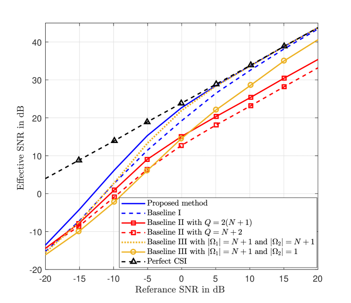
In Fig. 2, we plot the effective SNR versus reference SNR by varying the normalized noise power (i.e., ) from dB to dB with . First, it is observed that given the same number of training symbols, the proposed scheme achieves smaller MSE than the other baseline schemes and approaches close performance to the scheme with perfect CSI that yields an upper bound on the effective SNR. Second, in the high SNR regime, Baseline III with performs very close to the proposed method. This is due to the fact that at high SNR, it is very likely that only one candidate CSI achieves the minimum testing MSE. However, Baseline III in general requires exponentially increasing complexity due to the required exhaustive search of sign combinations, and thus is computationally prohibitive in practice. In contrast, the proposed scheme achieves superior MSE performance in both the low and high SNR regimes and requires low complexity (see (14)).
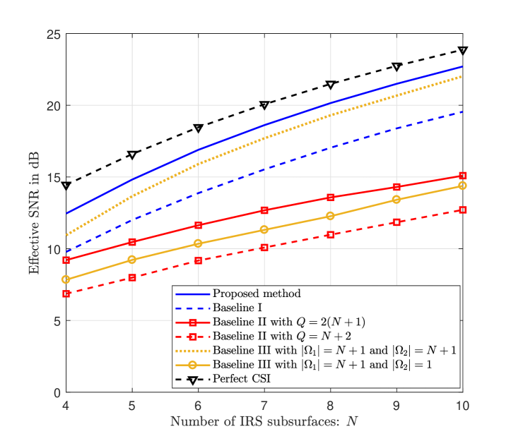
Next, we plot in Fig. 3 the effective SNR versus the number of IRS subsurfaces with fixed reference SNR of dB. It is observed that the proposed scheme significantly outperforms the other baseline schemes, and the performance gap between the perfect CSI case and our proposed scheme decreases with increasing . It is also observed that the performance of Baseline III with deviates away from that of Baseline III with as increases. This is because a larger requires more training symbols and hence more possible sign combinations that generally needs more training symbols in to determine the CSI with high accuracy.
V Conclusion
In this letter, we considered an IRS-assisted monostatic backscatter communication system, where an IRS is deployed to assist in the communication between a full-duplex single-antenna reader and a single-antenna tag. We proposed an efficient channel estimation scheme to estimate both the reader-tag direct channel and reader-IRS-tag reflecting channel, and optimized the IRS training matrix for minimizing the channel estimation error. Simulation results verified the superior performance of our proposed scheme over the baseline schemes. In future work, it is worth studying more general system/channel setups, such as the bistatic backscatter system [6], multi-tag system, IRS with discrete phase shift levels [15] or practical phase shift model [16].
References
- [1] Q. Wu, S. Zhang, B. Zheng, C. You, and R. Zhang, “Intelligent reflecting surface aided wireless communications: A tutorial,” IEEE Trans. Commun., DOI:10.1109/TCOMM.2021.3051897, Jan. 2021.
- [2] C. Huang, A. Zappone, G. C. Alexandropoulos, M. Debbah, and C. Yuen, “Reconfigurable intelligent surfaces for energy efficiency in wireless communication,” IEEE Trans. Wireless Commun., vol. 18, no. 8, pp. 4157–4170, Aug. 2019.
- [3] H. Lu, Y. Zeng, S. Jin, and R. Zhang, “Aerial intelligent reflecting surface: Joint placement and passive beamforming design with 3D beam flattening,” IEEE Trans. Wireless Commun., DOI:10.1109/TWC.2021.3056154, Feb. 2021.
- [4] F. Zhou, C. You, and R. Zhang, “Delay-optimal scheduling for IRS-aided mobile edge computing,” IEEE Wireless Commun. Lett., DOI:10.1109/LWC.2020.3042189, Dec. 2020.
- [5] W. Zhao, G. Wang, S. Atapattu, T. A. Tsiftsis, and X. Ma, “Performance analysis of large intelligent surface aided backscatter communication systems,” IEEE Wireless Commun. Lett., vol. 9, no. 7, pp. 962–966, Jul. 2020.
- [6] X. Jia, X. Zhou, D. Niyato, and J. Zhao, “Intelligent reflecting surface-assisted bistatic backscatter networks: Joint beamforming and reflection design,” [Online]. Available: https://arxiv.org/abs/2010.08947.
- [7] D. Mishra and E. G. Larsson, “Optimal channel estimation for reciprocity-based backscattering with a full-duplex MIMO reader,” IEEE Trans. Signal Process., vol. 67, no. 6, pp. 1662–1677, Mar. 2019.
- [8] C. You, B. Zheng, and R. Zhang, “Channel estimation and passive beamforming for intelligent reflecting surface: Discrete phase shift and progressive refinement,” IEEE J. Sel. Areas Commun., vol. 38, no. 11, pp. 2604–2620, Nov. 2020.
- [9] B. Zheng, C. You, and R. Zhang, “Intelligent reflecting surface assisted multi-user OFDMA: Channel estimation and training design,” IEEE Trans. Wireless Commun., vol. 19, no. 12, pp. 8315–8329, Dec. 2020.
- [10] T. L. Jensen and E. De Carvalho, “An optimal channel estimation scheme for intelligent reflecting surfaces based on a minimum variance unbiased estimator,” in Proc. ICASSP, May 2020, pp. 5000–5004.
- [11] C. You, B. Zheng, and R. Zhang, “Fast beam training for IRS-assisted multiuser communications,” IEEE Wireless Commun. Lett., vol. 9, no. 11, pp. 1845–1849, Nov. 2020.
- [12] L. Wei, C. Huang, G. C. Alexandropoulos, C. Yuen, Z. Zhang, and M. Debbah, “Channel estimation for RIS-empowered multi-user MISO wireless communications,” to appear in IEEE Trans. Commun., 2021.
- [13] D. P. Villame and J. S. Marciano, “Carrier suppression locked loop mechanism for UHF RFID readers,” in Proc. IEEE Int. Conf. on RFID, 2010, pp. 141–145.
- [14] T. L. Tung, K. Yao, and R. E. Hudson, “Channel estimation and adaptive power allocation for performance and capacity improvement of multiple-antenna OFDM systems,” in Proc. IEEE SPAWC, Mar. 2001, pp. 82–85.
- [15] Q. Wu and R. Zhang, “Beamforming optimization for wireless network aided by intelligent reflecting surface with discrete phase shifts,” IEEE Trans. Commun., vol. 68, no. 3, pp. 1838–1851, Mar. 2020.
- [16] S. Abeywickrama, R. Zhang, Q. Wu, and C. Yuen, “Intelligent reflecting surface: Practical phase shift model and beamforming optimization,” IEEE Trans. Commun., vol. 68, no. 9, pp. 5849–5863, Sep. 2020.