Project title:
Accelerator Real-time Edge AI for Distributed Systems (READS)
Institution: Fermi National Accelerator Laboratory (FNAL)
Street address: Wilson Street & Kirk Road, Batavia, IL 60510
Postal Address: P.O. Box 500, Batavia, IL 60510
Administrative Point of Contact: Hema Ramamoorthi
PI: FNAL Kiyomi Seiya Submitting User Facility: Fermilab Accelerator Complex at FNAL
DOE National Laboratory Announcement Number: LAB 20-2261
DOE/Office of Science Program Office: High Energy Physics (HEP)
DOE/Office of Science Program Office Technical Contact: Dr. John Boger
A Introduction and Motivation
Over the last decade, Machine Learning (ML) technologies have slowly made their way into the accelerator community. Rapid advances in recent years in deep learning, particularly reinforcement learning for control system applications and the accessibility of deep learning in embedded hardware, have generated renewed interest and spawned a number of applications [1].
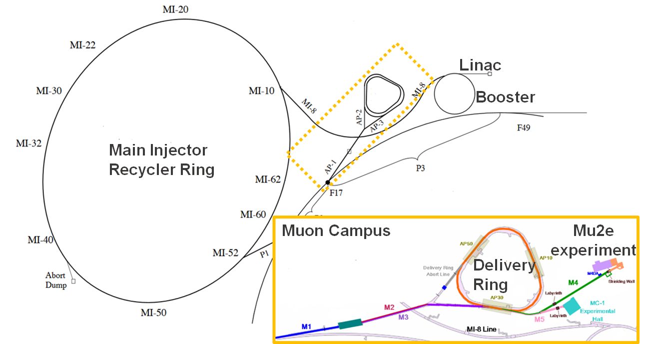
The Fermilab Accelerator Complex, shown in Fig. 1, has provided High Energy Physics (HEP) experiments with proton beams for nearly fifty years. The current focus of the laboratory is its world-class experimental program at the intensity frontier. While increasing beam intensity certainly presents its own challenges, preserving beam size while minimizing beam losses – particles lost through interactions with the beam vacuum pipe – turns out to be, in many ways, the main challenge. The accelerator is controlled via a complex system of hundreds of thousands of devices. Enabling fine tuning and real-time optimization of their parameters using ML methods and stepping beyond experience-based reasoning of human operators are key to the success of future intensity upgrades.
Our objective will be to integrate ML into accelerator operations and furthermore, provide an accessible framework, which can also be used by a broad range of other accelerator systems with dynamic tuning needs. To successfully maximize the benefits of applying ML, we will consider the following:
Real-time edge ML system optimization: An accelerator involves a complicated array of regulation loops for power supplies, RF and other control systems. The gains of the regulation loops are manually optimized and fixed for operations. In reality, beam distribution and intensity are dynamic quantities that evolve during acceleration. Consequently, these dynamic systems should ideally re-examine operating conditions in near real time. This requires an ML model capable of reacting to changes in the system on a sufficiently short, milliseconds, time scale.
Fast, intelligent distributed systems: Due to the large physical scale of particle accelerators, control systems tend to be spread across the facility. Optimizing the performance of each machine as well as the overall performance of the complex, therefore implies a fast data transfer system allowing for real-time communication between subsystems, machines, and computer resources tasked with running the ML algorithms.
Our project, Accelerator READS will develop ML methods and their edge implementation within large scale accelerator systems. Fermilab is a leader in the development of real-time embedded edge ML devices for system control and has leveraged ML to improve the efficiency and accuracy of HEP experiments such as the Compact Muon Solenoid (CMS) experiment [2]. Using the internal Laboratory Directed Research and Development (LDRD) program, Fermilab has demonstrated that a single ML system can improve accelerator performance. However, connecting embedded ML systems together to analyze and control multiple complex structures in coordination has not been done. The application of this technology to accelerators would be an evolution in capabilities towards fast, distributed, and high-performance control and operations of the Fermilab accelerator facility.
Methods and tools resulting from Accelerator READS will be relevant for design of a variety of complex and distributed controllers. We will demonstrate the effectiveness of our proposal with two experiments of significance: the Mu2e spill regulation system and the de-blending of the Main Injector (MI) and Recycler Ring (RR) beam losses.
Mu2e Experiment and Schedule
The Muon to Electron Conversion Experiment (Mu2e) is one of the major experiments in the Fermilab program whose construction phase is nearing completion. It is expected to come online in March 2022, succeeding the g-2 experiment. Mu2e will search for ultra-rare lepton flavor violating muon to electron direct conversion with a sensitivity four orders of magnitude higher than any previous attempts [3]. To achieve the goal, the experiment uses sophisticated apparatus and imposes very strict requirements on the quality of the proton beam delivered to the production target.
The former Antiproton Source storage rings and transport lines have been re-purposed and upgraded into what is now known as the Muon Campus, shown in Fig. 1. The 400 MeV protons are accelerated to 8 GeV in the Booster, transferred into the Recycler Ring where the beam bunch structure is optimized before being finally injected into the Delivery Ring (DR). While the bunch is circulating in the DR, it is gradually extracted to the target which is referred to as a spill.
The Mu2e experiment requires that Protons on Target (POT) be delivered over a running period of 3 years. Minimizing the downtime of the accelerator complex will be key to meeting this requirement as soon as possible. The experiment also requires that the extracted beam intensity within a spill be very uniform and the beam losses remain below 2% of the total beam power in order to control radiation and thereby reducing the equipment activation and personnel exposure.
Employing Machine Learning
We aim to use Machine Learning techniques to improve overall delivered beam performance to the Mu2e experiment and boost physics output by
-
•
improving the real-time spill regulation with the use of reinforcement learning algorithms for guided operations optimization thereby, increasing the Spill Duty Factor of slow spill extraction; algorithms will be developed with the aid of a digital twin of the spill regulation system
-
•
reducing beam aborts with intelligent and semi-autonomous operations by deploying de-blending and de-noising techniques to decouple overlapping beam losses in the Main Injector enclosure, thereby, increasing the overall uptime of the Recycler Ring (see Fig. 1), as well as delivering the beam to many other experiments across the entire complex
Both tasks will leverage capabilities unique to Fermilab in implementing real-time Machine Learning algorithms in embedded systems with millisecond scale feedback. Accelerator READS will develop shared machine learning tools, system instrumentation, and algorithmic techniques which can be deployed for beam delivery systems like Proton Improvement Plan-II (PIP-II) for future neutrino experiments and across other large accelerator complexes.
B Proposed Research and Methods
A collaboration between Fermilab and Northwestern University will pull together the talents and resources of accelerator physicists, beam instrumentation engineers, embedded system architects, Field Programmable Gate Array design experts, and ML experts to solve complex real-time accelerator controls challenges which will enhance the physics program. Deploying Artificial Intelligence (AI) systems at the millisecond scale or faster for low latency processes is beyond traditional online intelligent processing systems or human-in-the-loop controls. Developing the convergent aspects of advanced embedded system development and ML applications will build new AI capabilities that can be leveraged across Fermilab and resolve similar challenges at existing and future DOE facilities.
There are several elements to this proposed research deploying a range of techniques. In Section B.a and Section B.b, we describe two important challenges for delivering quality beam to the Mu2e experiment: the spill extraction of the proton beam from the Muon Campus Delivery Ring to the Mu2e experiment and the disentangling of beam loss signatures from the MI and RR accelerators in order to increase uptime of beam delivered to the Mu2e experiment, and consequently also improving overall performance of the Fermilab accelerator complex. In these sections, we will discuss how to augment beam monitoring instrumentation for real-time ML capabilities and where ML can be used to enhance the systems. In Section B.c, we discuss how to aggregate the signals from distributed instrumentation into a single data pipeline for online controls systems and for offline storage to perform data analysis and train ML models. Section B.d will reformulate the accelerator challenges into the ML domain and discuss how modern machine learning techniques will be deployed for these applications. Finally, in Sec. B.e, we will discuss implementation and system aspects of deploying machine learning models within the operational controls system of the Fermilab accelerator complex and the novel challenges for building intelligent embedded hardware systems. PI Seiya, who has 20 years of experience in Fermilab AD operation and beam physics, will be coordinating activities across the entire project.
B.a Regulation Loop for Mu2e Slow Spill
The goal of the regulation loop is to deliver a spill with a highly stable intensity profile. This necessitates fine control of the spill regulation process. We propose to deploy an ML agent to adjust the Spill Regulation System (SRS) parameters in real-time by providing feedback at the approximately milliseconds timescale. Co-PI Nagaslaev and Co-PI Ibrahim are project leads in the spill regulation system design for the DR and will guide ML integration.
Operational Overview for Slow Extraction
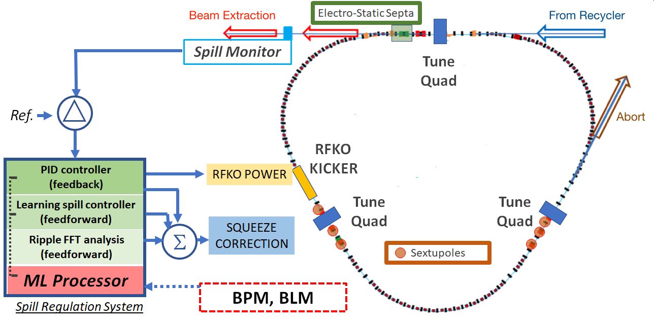
The layout of the slow extraction components in the DR is shown in Fig. 2. The process of slow beam extraction is achieved by creating the resonance condition with the use of dedicated sextupole magnets. The fraction of beam particles that fall into the resonance and become unstable is controlled by the tune ramping quads. These magnets drive (‘squeeze’) the machine operating point (tune) to the exact resonance, gradually pushing the entire circulating beam out of the stable condition. As unstable particles drift towards the machine aperture, they get intercepted in the Electrostatic Septum (ESS) and deflected towards the extraction line. The extracted beam is a stream of 200 nanoseconds. wide pulses, separated by the DR revolution period of 1,695 nanoseconds.
Spill Regulation System
The objective of the SRS is to maintain the intensity uniformity of the pulses extracted from the DR to the target area. The quantitative metric which defines beam stability is called the Spill Duty Factor (SDF) which is defined as:
| (1) |
Here, I is a single pulse intensity. The design value of the SDF is 60%. It is very important for the experiment to have this value as high as possible. Large intensity variations in the spill will saturate the throughput capability of the Mu2e data acquisition system and create dead time issues in the readout system resulting in the loss of useful detector data. Substantial increases of the SDF value typically require a large effort over a long period of time [4], [5]. This proposal has a great potential to significantly improve on the SDF limit through the exploration of ML and hence, increase the Mu2e uptime.
The Spill Regulation System is implemented in the Intel Arria10 SOC with custom carrier board (Fig. 2, left) and it has several control loops. The main way to control the extraction rate is by regulating the voltage reference current to drive the tune ramping quads. The ramping curve of quad excitation determines the shape of the beam intensity profile during the spill. The other handle to control the extraction rate is the fast modulation of the RFKO system. RFKO is used to effectively heat the beam in the horizontal plane and accelerate the diffusion of particles into the unstable areas. The SRS uses the PID control loop to simultaneously regulate these two primary beam correction elements.
The loop will use the spill monitor intensity measurements to monitor the instantaneous and integrated spill parameters. This signal will be provided as a reference for the fast PID loop and as an input for the two other loops.
ML for the Spill Regulation System
The PID loop parameters (gains) need to be re-optimized in real time. This can be done very effectively with ML. Moreover, in this case the loop gains can be expanded into a nonlinear time-dependent series to provide a better coverage of the regulation frequency range.
Bringing the ML agent into the process opens the way to extend the operational functions of the SRS with inclusion of new environmental inputs: (1) the turn-by-turn beam position monitor (BPM) signal and (2) Beam Loss Monitor (BLM) in the DR.
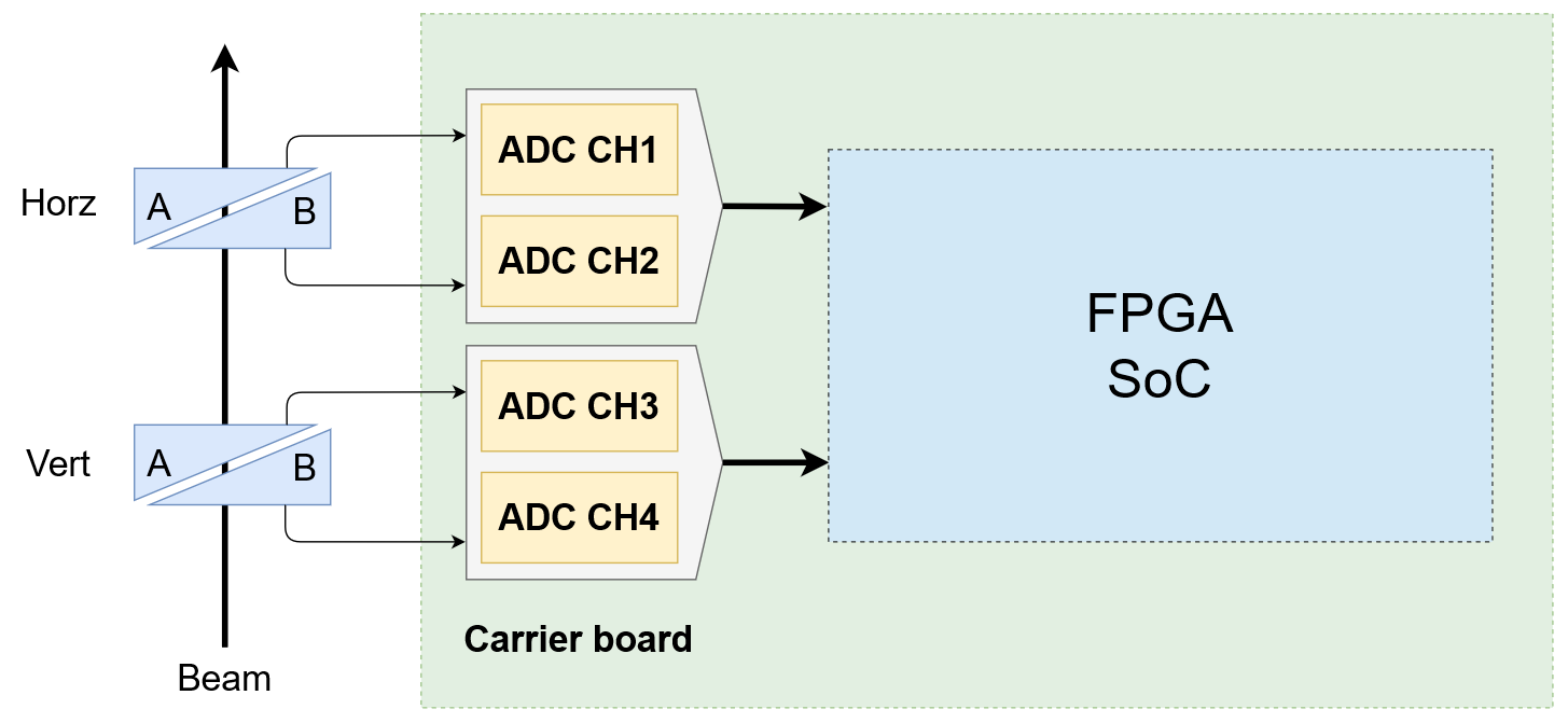
The turn-by-turn beam position measurement (Fig. 3-left) can be used to calculate the injection beam steering error. This error may have a substantial random component, leading to an unpredictable distortion of the beam shape and therefore, the spill profile. The analog signal trace for the first 50 turns can be digitized and analyzed in the Spill Regulation System to provide immediate information on the beam shape change for every spill. The ML process will help to determine the algorithm for spill-to-spill corrections for the squeeze waveform.
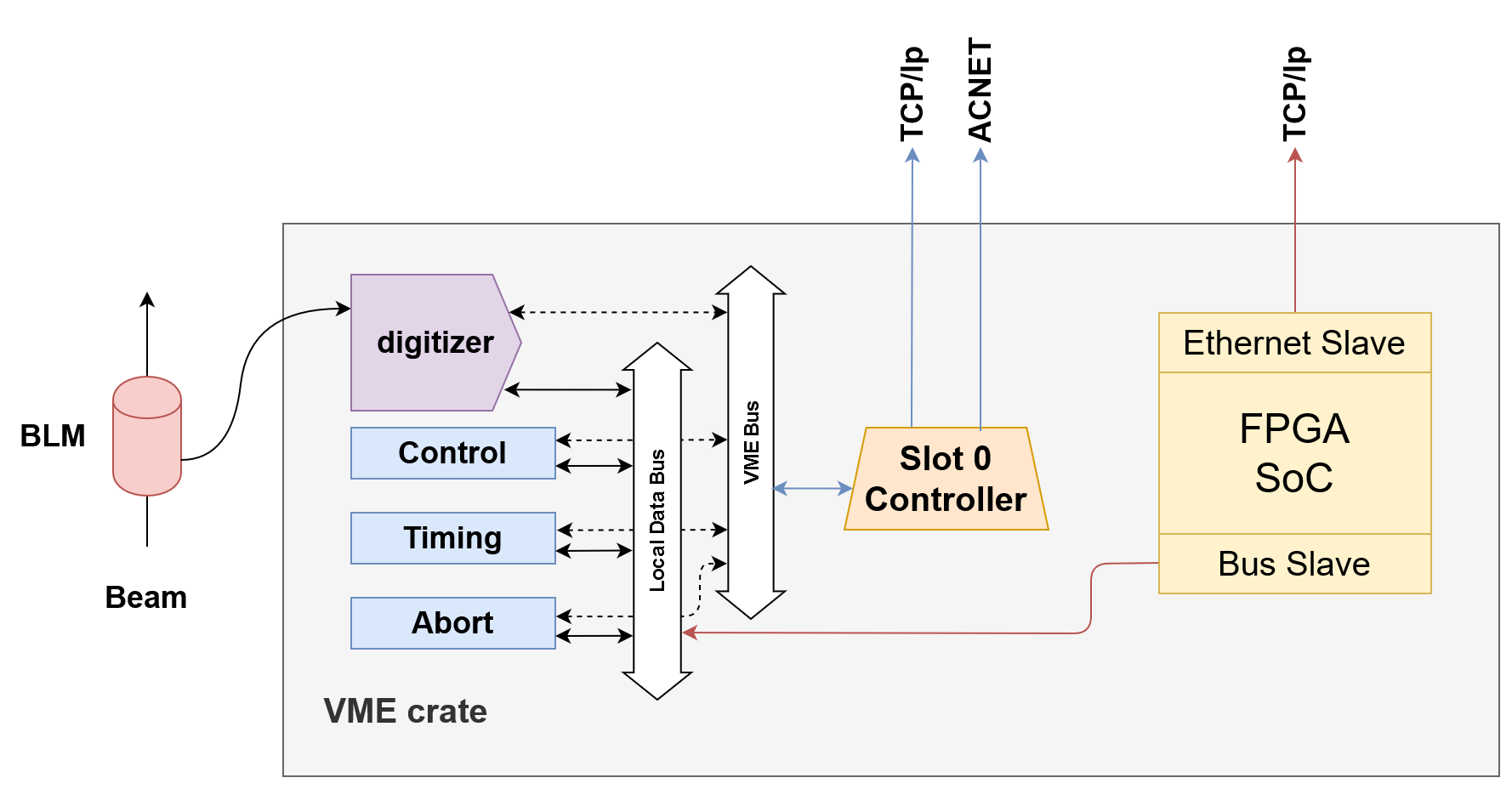
Small beam losses at the design level near 2% create significant radiation constraints with the beam power of 8 kW. To mitigate this, 1 m thick iron shielding is installed above the ESS in the tunnel. Safety systems are in place to instantly shut down the beam operations if beam losses exceed the permitted level. Monitoring and improving the losses in real time becomes now possible with the use of the BLM data (Fig. 3-right). The data analysis is very similar to that proposed for the de-blending of the RR/MI losses and will be discussed in detail in section B.b. The ML process will track the changes in the loss pattern to identify new sources of beam loss and initiate corrections to the extraction control elements. This will improve the uptime in the DR.
B.b De-blending of Main Injector and Recycler Beam Losses
The second demonstration of our Accelerator READS concept will be through the de-blending system. Co-PI Hazelwood is a senior engineering physicist in the Main Injector department at Fermilab and has extensive experience in accelerator controls and has designed ML algorithms for beam physics reconstruction.
Operational Overview of Beam Loss Monitoring in the Main Injector Enclosure
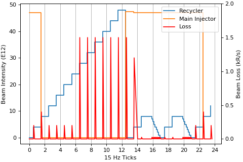
The Main Injector enclosure houses two accelerators; the Main Injector, which is a 120 GeV conventional powered magnet synchrotron and the Recycler, which is an 8 GeV permanent magnet ring. The Recycler was originally commissioned as an anti-proton storage ring for the Tevatron collider. Anti-proton intensities in the Recycler during the collider era were relatively small compared to the proton intensities going through the Main Injector, hence, de-coupling beam loss from the machines was of little concern. Since the end of the Tevatron collider era, the Recycler has been re-purposed as a proton stacker for 120 GeV NuMI beam operation [6] as well as 8 GeV muon campus beam operation [3]. The new modes of operation mean high intensity proton beams are often simultaneously running in both the Recycler and the Main Injector. High intensity beam in the Recycler also means the possibility of higher beam loss. Beam losses in the Recycler often rival those of its sibling machine, the Main Injector. Beam losses in the Main Injector enclosure are monitored for both tuning the accelerators and machine protection. Seven beam loss monitor nodes are distributed around the 2.2 mile Main Injector enclosure (Fig. 1) to monitor all 259 operational ionization chamber beam loss monitors. Readings from these nodes are transmitted to ACNET, Fermilab’s accelerator control system. The nodes also actively compare loss readings against set thresholds to trigger beam aborts for either machine. While separate loss thresholds may be set for each machine, in practice the limits for both machines are set conservatively, because we are unable to accurately attribute loss to the correct machine. This means that the vast majority of the time losses from one machine will cause a beam abort in both machines resulting in unnecessary downtime of the sibling machine.
Expert Beam Loss Machine Attribution
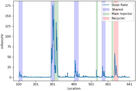
While losses are currently attributed to a machine based on timing, this method alone is insufficient and often inaccurate. Machine experts can often distinguish losses between machines better than the current system. Loss patterns exist such that those with knowledge of the machine can look at all the BLM s around the enclosure and pick out patterns in time and location to help attribute loss to a particular machine. As Fig.4-left shows, time of loss can be a great indicator as to what machine caused the loss. Examples of time based losses are start of ramps, collimation bumps, injection and extractions, all of which are particular to a cycle and indicate a certain machine. Location and shape of loss patterns are also very helpful. The Recycler Ring and the Main Injector have known aperture restrictions, that are areas where the beam is most likely to be lost when problems arise. Some of the Main Injector’s and Recycler’s aperture restrictions are unique to their respective machine while some locations have overlapping common loss points (Fig.4-right). In places where the two machines share aperture restrictions near the same physical location, such as injection and extraction locations, the loss pattern shape can help discern which machine caused the loss. Losses often appear first in one BLM followed by a ”spray” of losses. Depending on the machine, loss spray may be revealed or masked by components in the accelerator. The goal of this project would be to replicate and improve upon what experts are attempting to a limited extent to attribute loss to a machine.
Real-time Beam Loss De-blending using Machine Learning
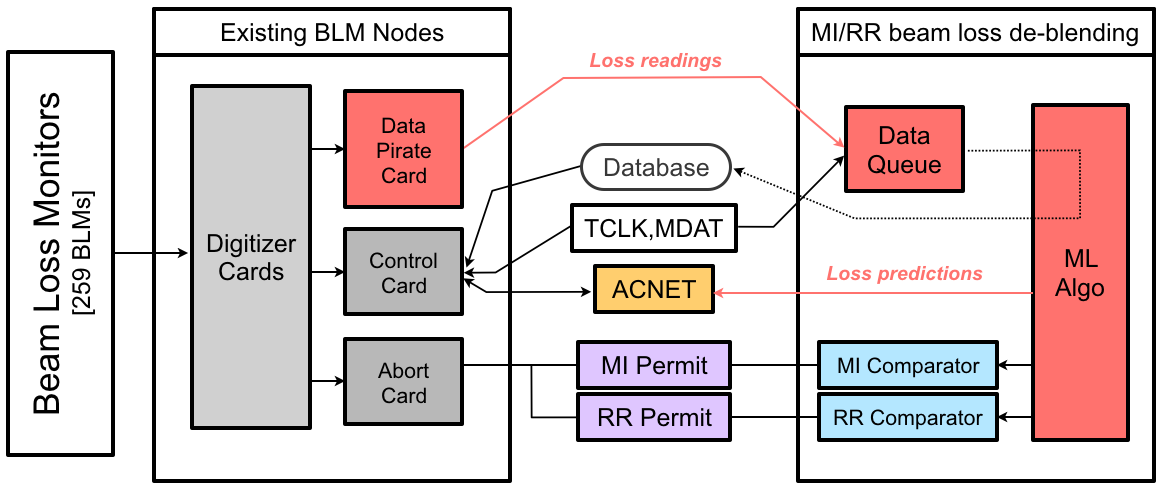
It is beyond the scope of this proposal to completely replace the existing Main Injector enclosure beam loss monitoring system. The cost of doing so is too great and current schedules require that the BLM system remains functioning. For these reasons, we are proposing a system that leaves the existing BLM infrastructure virtually unchanged. Instead, the current BLM nodes would be utilized to feed beam loss readings to a central node that will then use a trained ML model to de-blend losses and label them by machine. As seen in Fig. 5, to facilitate reading and transmitting loss measurements at high rates (200-1440 Hz) without tasking the existing BLM nodes, new loss reading “pirate” cards will be developed to listen to the control bus on each crate and transmit readings over ethernet to the central node. The central node would use a data queue to aggregate loss readings from around the ring as well as information deemed to be useful such as clock or beam intensity. Data sets created from the data queue would then be fed to the ML model. The output from the ML model will be made available to ACNET for machine tuning and diagnostics. The ML output will also be used to decide whether or not to disable a machine’s beam permit due to excessive beam losses. In order to properly protect the machines and serve as a useful tool for tuning, ideally the ML model should provide output at no less than 200 Hz frequency.
B.c Data Pipeline, Storage, and Computation
Successfully implementing ML in an embedded systems environment will require additional hardware and software to support a data processing pipeline which is capable of ingesting, archiving, validating, and training an appropriate set of accelerator data. We consider three primary phases of the data flow: (i) the data being created at the beam instrumentation after digitization and transmitted to the online processing ML algorithm; (ii) nearby edge compute resources for re-optimizing the agent in real-time; and (iii) offline data storage and archiving for large scale training using on-premises resources or the cloud.
For the phases (i) and (ii) of the data flow, we require communication protocols for streaming digitized data off of custom data buses to FPGA s capable of handling large data rates with low latency. The data ingested by the FPGA is then sent to a more traditional CPU architecture where it will be transmitted by ethernet to the processing ML algorithm, which in turn will be deployed on another FPGA device. This fast generic FPGA-CPU communication will be a central capability of the project and implemented for several data pipelines, transmitting sensor data and also streaming data from the online algorithm to offline computing elements.
Fermilab Accelerator Division has been developing control modules based on the Intel Arria10 System on Chip (SOC), an integrated ARM-based CPU+FPGA device, and is planning to standardize them for control systems and instrumentation. The two projects described in Section B.a and Section B.b, require development of FPGA modules which allow for the reception of data packets from the existing Versa Module Eurocard (VME) crate and transmittance to a central module at a high speed. We envision that this board will be the common development platform for the proposal and has the requisite capabilities to deliver on all the needs of this project.
Phase (iii) of the data flow requires storing and archiving data from the online processing node to build a large scale digital twin of the accelerator system. Commodity disk space, time-series databases, cloud services for the large-scale phases of training, and on-site compute nodes (CPUs) with GPU support will all be a part of the available data ecosystem. These resources will help with creating beam simulations for initial model training, data pre-processing, and organization for beam data itself. For model training, we will consider on-premises GPUs for smaller scale and simple ML model training, while for large-scale burst training, we will allot cloud-scale resources.
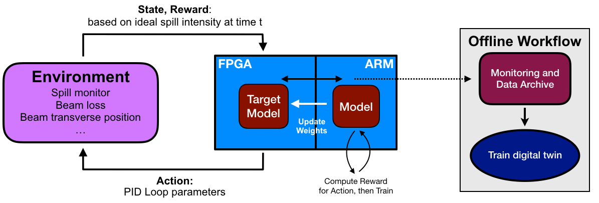
An illustration of an example of the entire data pipeline with ML model feedback loop for the spill regulation system is presented in Fig. 6. It is also relevant for the beam loss de-blending application as well. The illustration shows the multiple data pathway phases from the raw instrumentation data transferred to the ML processing, the FPGA to CPU communication, and the streaming to offline data storage for large ML training workflows.
In the next section, Section. B.d, we will discuss the aspects of Fig. 6 pertaining to the development of the machine learning models and the creation of input and training data. In Section B.e, we will discuss how we will implement those ML models into the FPGA fabric itself for real-time online operations.
B.d Machine Learning Model Development
In this section we will elaborate on our proposed ML methods that are tailored to the needs of different accelerator control problems. This part of the project will be led by Co-PI Liu who has an extensive expertise and background in ML and leading ML projects.
Reinforcement Learning for Controlling the Spill Regulation System
SRS simulations
A full suite of physics simulations can be used to study the regulation algorithms enhanced by ML while the beam instrumentation and controls are being developed. This will inform the early stages of the ML model studies in a well-understood simulation environment.
The detailed simulations of the slow spill regulation have to include a large number of physics processes and the statistical nature of the extraction process. Such a modeling of the extraction process takes substantial computing time using grid resources. We have expertise on performing simulations at this complexity [7]. For the purposes of studying the regulation process, the model can be significantly simplified. The new model would replace the most time-consuming part of beam dynamics with an analytical model, which is, with a few exceptions, still adequately representative for the most significant extraction response to the sources of variation. This model can be used for fast MATLAB simulations to test the real-time firmware and provide data sets for the offline training of ML models.
ML Model Building
The primary function of the control loop in the Mu2e slow spill is to tune the RFKO power and the quadrupole correction currents. The goal is to maintain a consistent spill intensity to achieve a high Spill Duty Factor as defined in Eq. 1. We plan to target a class of reinforcement learning techniques [8] which model the control loop as an online agent taking action to tune the RFKO and quadrupole systems. The action , which will be selected by the learned policy based on the current state , generates a stimuli to the environment which updates the state of the agent and a reward is computed based on the ideal spill intensity for a 100% Spill Duty Factor. This reinforcement learning loop is depicted in Fig. 6. Our main goal is to maximize .
The online agent takes a large number of environmental inputs of various timescales. To reduce system risk and fully harness the potential of the reinforcement learning agent against a traditional PID controller, we propose a phased implementation of the model considering two paradigms: model-free and model-based learning. Consider a traditional PID controller based on a model where are model parameters. In a model-based paradigm, the online learning agent learns the parameters of and exploits them to evaluate the transition probability from state to state if action is performed. The development of the digital twin is performed offline using a large training sample. We will fine tune this model with meta learning techniques to better imitate the real environment.
One striking feature of our proposed machine learning algorithms is their real-time performance guarantee. We propose two strategies to achieve this: (i) a hierarchical architecture; (ii) a Quality-of-Service (QoS) protocol. Hierarchical reinforcement learning [9] incorporates hierarchies into the representation of actions taken by the online agent. Such a hierarchical representation eliminates unnecessary decision branches and sketches appropriate actions with lower granularity, thus increasing its time efficiency. In contrast, QoS provides a systematic framework to trade off the decision speed and quality. An integration of the two delivers a stronger performance guarantee for the resulting algorithms.
Supervised Learning for De-blending Main Injector and Recycler Losses
Creation of Machine Labeled Beam Loss Training Data
Current modes of operation do not allow much time to collect training data when the beam is only in one machine at a time. Creating a sufficiently large set of accurate machine labeled beam loss training data by monitoring operations is not feasible. Accelerator beam loss simulations of the machines are also not very useful because losses often occur due to small imperfections such as beam pipe welds or miss-alignments that are not accounted for in our accelerator models. Therefore, an initial training data sample with dedicated beam studies using actual accelerator data will be collected during beam commissioning periods. In such a study, the beam would be injected into only one machine at a time and loss would be created in various ways at varying locations and times. All BLM s would be recorded at a frequency needed to train a model for real-time loss de-blending. Other information such as clock (TCLK), permit status, and Machine Data (MDAT) would be recorded as well. Running conditions and operational modes in both the Main Injector and the Recycler change throughout the year. This project lends itself nicely to incremental training where data from operations is used to improve the initial ML model. The use of incremental training will be explored to lessen the need for costly beam loss studies.
ML Model Building
The goal of de-blending Main Injector enclosure losses is to differentiate between the beam loss from the Main Injector and the beam loss from the Recycler by analyzing the beam loss monitors’ readings. We plan to implement a supervised machine learning algorithm to tackle this. In this problem, we have response variables and inputs (predictors) . denotes the respective desired labels for categorizing the BLM s, indicating whether the beam loss comes from the Recycler or the Main Injector. The inputs , on the other hand, represent the readings from the BLM s and other monitors. We aim to learn a prediction function that maps the inputs to the response variables by minimizing a cross-entropy loss function to predict the true beam loss categories.
Minimizing the above objective function is a stochastic optimization problem. To solve it, we start with a batch setting to get an initialization of our machine learning model, and then utilize incremental learning techniques to refine our model in the online setting and adapt it to different operational modes of the machine. For the batch setting, we will first use coarse training data that could be properly labeled by machine and then obtain a pilot estimator by training a model on that sample. After the model is deployed, we will conduct incremental learning, which is similar to model fine tuning with Stochastic Gradient Descent (SGD) method.
The major novelty of the proposed method is its real-time performance guarantee. In other words, solving the above optimization problem subject to a time constraint . Since the algorithm will be implemented on an FPGA, to accelerate model inference in a real-time, we propose two approaches for optimizing the ML model in a resource-aware fashion: (i) We conduct model compression [10] for existing models to lower their usage of computation resources and, at the same time, maintain original performance. For example, it can be realized by pruning inactive branches of neural networks to simplify the model [11], or by lowering precision of the model parameters [12]. (ii) Furthermore, we will use Neural Architecture Search (NAS) [13] methods to search for models with high enough performance and short enough inference time. NAS is a meta-learning technique for automatically searching the optimal neural network. We could search for a model satisfying the time budget by limiting the number of floating-point operation s (FLOP s) in the objective function of NAS.
B.e Model implementation and system architecture
To implement the powerful ML algorithms developed in Sec. B.d, we rely on co-design – the idea that system constraints, algorithm development, and hardware implementation inform and guide each other in complementary ways. For accelerator operations, there are hard real-time latency constraints for very low latency processes. Therefore, we will explore hardware co-design for high-speed embedded technologies using FPGA s. This project will develop a co-design methodology that is focused on providing cost-effective and highly tuned AI control systems with a quick turn-around time. Co-PI Tran and Co-PI Memik have strong expertise in developing optimized embedded FPGA systems for ML algorithm implementations and other real-time applications.
Algorithm-Architecture Co-Design
This project will explore a variety of AI methods (e.g., hierarchical and QoS-driven reinforcement learning and supervised learning) to cater to the unique natures of the spill regulation and de-blending applications. However, we note that the co-design methodologies developed in this project will serve as templates for a large class of AI methods in control design for experimental sciences. The common denominator is the underlying FPGA SOC hardware. The role of the co-design task is to construct a ubiquitous tool chain for mapping a variety of deep learning networks and their support systems (e.g., online learning module, communication interfaces, etc.) to the FPGA SOC, strategically re-organize resource allocation with an awareness of the target hardware platform’s capabilities, and direct the design tools towards optimal system settings. The core computational module performing inference will be housed on the re-configurable logic of the FPGA SOC. Optimizing the performance of this module directly impacts the real-time performance goals of the system. Neural networks are generally characterized through a number of multiplication and addition operations using fitted parameters (weights) determined during the training procedure. By reducing both the number of mathematical operations and how often the weights need to be accessed, the implementation can be made more efficient. Further, the precision at which the calculations are performed is also important. Just as important is to learn the most important features of the data for our challenge; learning the right representation as efficiently as possible can reduce computational complexity.
Co-PI Memik has extensive experience in developing analysis methods to identify performance bottlenecks in reconfigurable computing applications [14] and for machine learning applications in general [15]. As part of this task, we will perform analysis of the sensitivity of each learning model to the availability/scarcity or performance of a specific resource in our target device. For instance, for FPGA hardware, width, depth, and connectivity of a network, precision of weights (resulting total storage and interconnect) will have varying correlations with the given capacity of different types of device resources (interconnect, embedded RAM, embedded DSP blocks used for multiply-accumulate operations, etc.).
Programming Paradigms and Tools
The main goal in developing programming paradigms and tools will be to increase accessibility of hardware implementations of algorithms in order to accelerate the development cycles for AI instrumentation. Mature programming tools are absolutely vital to wider deployment and adoption which will in turn improve the overall physics design process.
We will align our tool development strategies with the unique aspects of AI computation. One of the key features of neural networks is their modularity. This allows us to develop programming paradigms that enable the developer to separate and recombine these specific modular units to build larger neural network architectures. The basic description of the AI circuit implementation, for example, can be described in a low level hardware description, but each kernel would be configurable based on resource, latency, and bandwidth constraints.
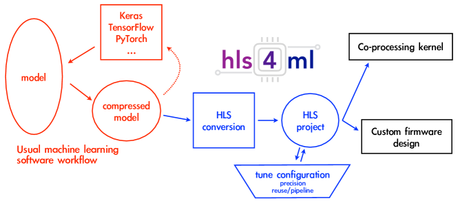
We will leverage a tool called hls4ml [2, 16, 17], which takes popular open-source machine learning software frameworks such as TensorFlow, Keras, and PyTorch and converts their model descriptions into High Level Synthesis (HLS) code; e.g., C++-based code. Co-PI Tran is the leading developer of this framework. The HLS code is then converted by the Intel HLS Compiler into a digital circuit implementation targeting the Arria10 FPGA. Unlike a pure C++ description of computation, the HLS code is enhanced by special parameters (pragmas) which explicitly instruct the Intel HLS Compiler to tune the performance of the underlying hardware description to customize it for different system constraints. The full workflow of hls4fml is depicted in Fig. 7. Despite being a new software package, this tool has seen widespread adoption in the HEP community and has been successfully used for fully-connected neural networks in LHC trigger applications on FPGA s. Co-PI Memik will leverage her expertise on design automation tools for reconfigurable architectures [18, 19, 20] and extend the capabilities of the Intel HLS Compiler through systematic exploration of the HLS pragmas.
System Design and Integration
Solutions will be needed for integration of the AI implementations into a coherent accelerator control system, including: interfacing AI kernels to components such as power and memory management, device infrastructure and controls, and networking protocols; communication with other devices in both a homogeneous and heterogeneous hardware stack; software interfaces with the operators and users for features such as neural network weight programmability and neural network training and feedback loops. Co-PI Memik has past experience on design of real-time applications on FPGA s [21, 22] and co-designing reconfigurable hardware/software systems [23]. She will explore the optimal partitioning of the integration components within the Intel Arria10 SOC.
An example of a conceptual system, which includes the three aspects listed above, is shown in Fig. 6. Illustrated here is a dynamic reinforcement learning architecture for a generic system which controls an experimental apparatus. This topology serves as a realistic representation for the applications considered in this project. The main component in this system is the Intel Arria10 SOC. This system communicates with a high-speed data acquisition system which aggregates data in long term storage for offline model training as well as for the development of a complex digital twin. As the coarse grain features of the models are discovered through offline training on GPU s, incremental updates will be performed on the model through the dynamic feedback loop within the Intel Arria10 SOC.
The target model for controlling the experiment is shown in the red box labeled “Target Model”. Batches of data are recorded and used to continue training the model based on a desired reward. The target model will require an interface which provides a mechanism to update the weights via the ARM system responsible for training on real-time data. Updating the target model in this manner will require a thoughtful approach to system integration and FPGA firmware infrastructure. While this is but a simplified example, it serves to illustrate the interfaces required to implement a configurable embedded ML system.
C Timetable of Activities
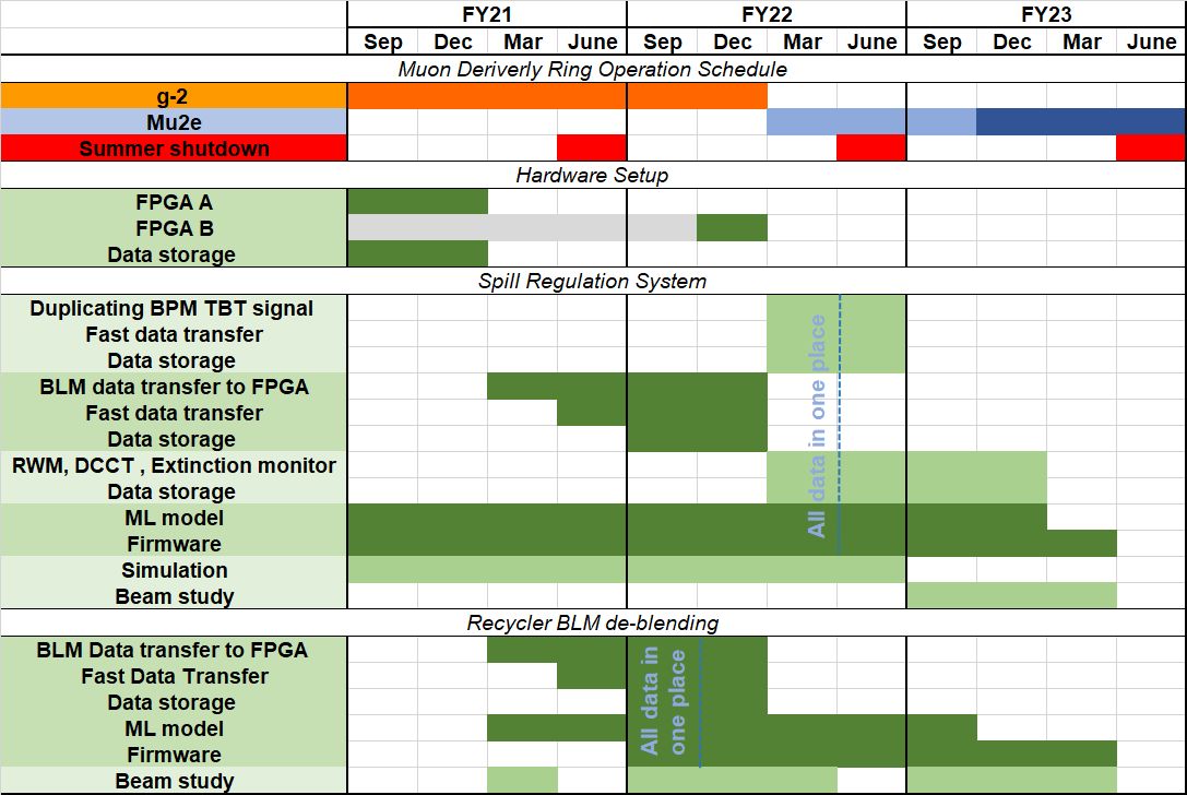
This proposal requests three years of support to complete two main projects: integrating ML into the spill regulation system and de-blending the MI and RR BLM signals. Table 1 shows the timeline for our proposal and includes the accelerator operation plan. This schedule assumes that funding begins in September 2020 and that the accelerator complex will continue to have a 12-week summer shutdown for the next three years. The ongoing experiment at the Muon Campus, g-2, is predicted to end by March 2022. Beam commissioning for the Mu2e Slow Extraction will start in the Delivery Ring in late 2022. At this time low intensity beams will be slowly extracted to the temporary dump on a regular basis which can be used for beam studies of the SRS. Dedicated time for ML studies will easily fit into the schedule of machine development. During the operation of the g-2 experiment, it is expected that the RR will deliver beam with intensities and injection patterns similar to both g-2 and Mu2e experiments, enabling the development of Mu2e ML beam studies.
The work packages in this proposal fall into 5 different types: (i) extract low latency signals from instrumentation; (ii) transmit and store the data elements; (iii) conduct beam studies and simulation to collect training data for the ML models; (iv) build and train ML models, surrogate models and an online agent; (v) implement the ML model on the FPGA and set up an online training system, coordinating the FPGA and the embedded CPU of the SOC package. The project work packages and their timeline is shown in Fig. 8. Further, project milestones based on these work packages are shown in Table 1.
| Spill Regulation System | |
|---|---|
| FY21 | Transmit existing BLM system data to the FPGA board |
| Build ML models using an analytical model of the spill regulation loop. | |
| FY22 | Transmit BPM/BLM system data to centralized FPGA board, then transmit to data storage. |
| Establish ML models, surrogate models and online agent, for controls using all input signals and data in the storage. | |
| Implement the ML model into the FPGA board | |
| Test the spill regulation loop with ML. | |
| FY23 | Conduct beam studies and measurements, study ML performance. |
| MI/RR BLM de-blending | |
| Transmit existing BLM system data to the FPGA board from 7 nodes | |
| FY21 | Conducting beam studies and measurements and accumulating data for training. |
| Establishing ML models, surrogate models and online agent, for controls using all input signals and data in the storage. | |
| FY22 | Implementing the ML model into the centralized board, FPGA board |
| Conduct beam studies, and compare the results between original system and the one with ML. | |
| FY23 | Set up necessary control parameters and monitors and replacing the machine permit consolidation system with the new ML system for operation. |
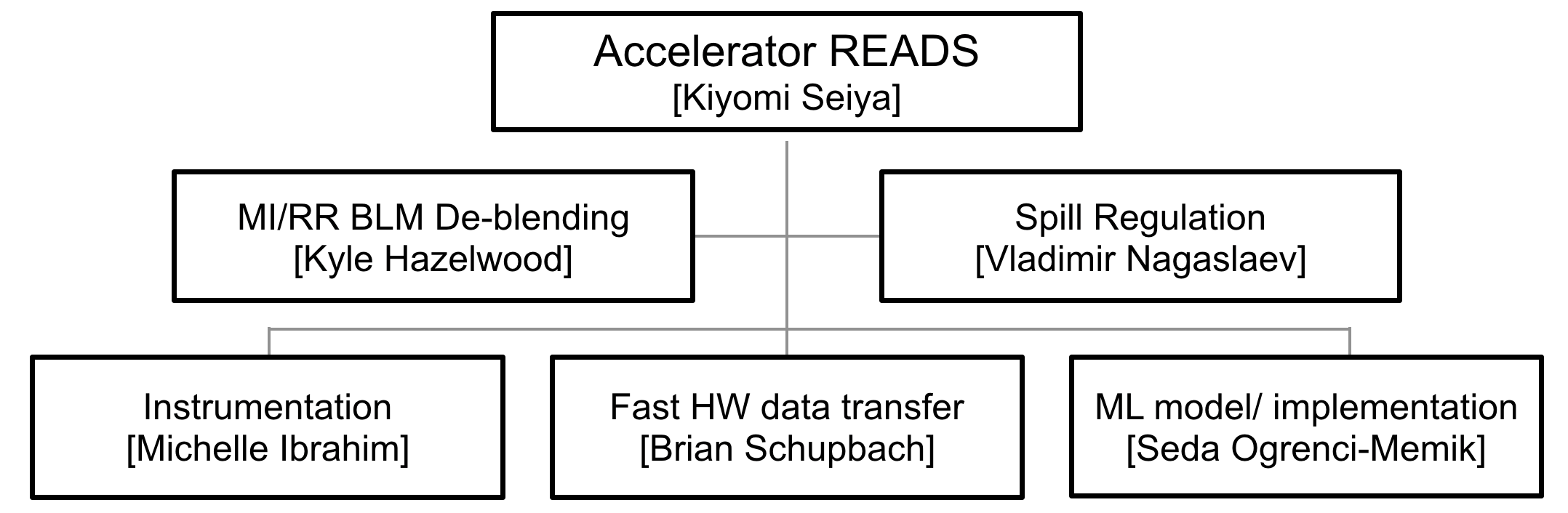
D Project Management Plan
This proposal is composed of two primary deliverables: MI/RR BLM de-blending and Slow spill regulation. It brings together a strong multi-disciplinary team with accelerator physicists, beam instrumentation engineers, embedded system architects, FPGA board design experts and Machine Learning experts. The project management plan is presented in Fig. 9 and has two physics focus areas and three technical focus areas with coordinators for each. The multidisciplinary project team will consist of Fermilab staff crossing division boundaries and collaborators from Northwestern University. Furthermore, the proposal provisions for effort from instrumentation engineers, controls and computer engineers, an ML research associate, and graduate students to drive the work plan under the management team. They will receive the support and mentoring by other staff members to ensure this project will be an informative experience that will advance them along their career paths. Experienced and knowledgeable experts lead the physics and technical teams and ensure our goal is achieved in three years.
The roles and responsibilities of the individuals are as follows:
Lead PI: Kiyomi Seiya, Senior Scientist in the Accelerator Division (AD), who has 20 years’ experience in Fermilab AD operation and beam physics, organizes the team, coordinates the schedule and budget and ensures that this project aligns with the laboratory’s schedule.
Accelerator Physicists: Kyle Hazelwood, Engineering Physicist III in the AD Main Injector department, has been working on AD operations, accelerator controls, and beam physics for 13 years and leads MI/RR BLM De-blending. He is responsible for beam studies and analysis and coordinates the required hardware and software with the technical development teams. He will collaborate with the technical development teams on ML model development. Vladimir Nagaslaev, Senior Scientist in AD for 18 years, who has been responsible for design and implementation of the Slow Extraction for the Mu2e project, leads Spill Regulation.
Instrumentation: Michelle Ibrahim, Senior engineer in the AD Instrumentation department, leads the Instrumentation team. Ibrahim has been developing the spill regulation system for the Mu2e project and is an expert on signal processing for the beam diagnostics system. Engineer A, who is a new hire, focuses on code development on the FPGA board which receives data from the existing system under Ibrahim’s supervision. Engineer A also digitizes, and processes all input signals into an FPGA board which will be used for the spill regulation system.
Hardware and Fast Data Transfer: Brian Schupbach, Staff Engineer and an Low Level RF expert, leads the Hardware and Fast Data Transfer team. Schupbach developed an FPGA board for a Fermilab LDRD project to implement ML into a bending magnet power supply regulation system. Schupbach is responsible for all FPGA board development and necessary modification. Dennis Nicklaus Software Engineer, will develop fast communication protocols via ethernet which allow for fast data transfer between multiple FPGA boards with Schupbach. Nicklaus will be responsible for testing fast communication between the distributed systems.
ML Model and Firmware: Seda Ogrenci-Memik, Professor at Northwestern University, leads the ML model and Firmware team and implements ML models into fast embedded systems which are based on the Arria10 FPGA SOC system with graduate student A. She will collaborate with Co-PI Tran on the embedded systems design and automated tool development to support the design efforts of the project. She will also collaborate with Co-PI Liu on hardware/resource-aware ML model compression. Nhan Tran, Scientist in AI, is an expert on fast embedded system support hardware and software development and tracks the progress of the project. He will support a Fermilab AI research associate. He will collaborate with Co-PI Memik on ML hardware implementations and Co-PI Liu on ML model development. Han Liu, professor at Northwestern University, develops ML Models, surrogate models and an online agent with graduate student B. A research associate in Al works on both ML modeling and firmware development with the collaborators.
E Project Objectives
The overarching goal of our proposal, Accelerator Real-time Edge AI Distributed System (Accelerator READS) is to combine a ’Fast embedded ML’ system and a ’Fast data transfer system’ to improve the operation of large accelerator complexes by means of global ML based supervision. We will demonstrate these techniques with two experiments of significance: the Mu2e spill regulation system and the de-blending of MI and RR beam losses.
In the first instance we aim to increase the Spill Duty Factor of slow spill extraction with the use of both model-based and model-free reinforcement learning algorithms to assist the spill regulation in real-time increase the uptime. In the second instance, supervised learning algorithms will be used to decouple overlapping beam losses in the MI/RR enclosure to reduce beam aborts.
The Mu2e construction phase is currently nearing completion; Mu2e is expected to come online as the g-2 experiment winds down. On a relatively short time scale, Machine Learning techniques have the potential to significantly enhance the experimental physics output by improving the performance of beam delivery.
Successfully implementing ML in a fast-embedded systems environment will require the development of a data processing pipeline, hardware and software. The process is as follows: (i) development of control modules based on the Arria10 SOC FPGA system to allow for the reception of data sets from the existing instrumentation and for the extraction of low latency signals to be used as training inputs for ML. (ii) development of a high-speed data transmission protocol between distributed FPGA modules and of associated infrastructure to transmit data elements to central modules and put them into data storage; this includes a computing server for user interface, data storage, reprocessing, and manipulation. (iii) conduct beam studies and simulation to support ML model development, build ML models, surrogate models and an online agent. (iv) implement the ML model on central modules and set up an online training system by developing code using hls4ml.
A collaboration between Fermilab and Northwestern University will synthesize the talents and resources of accelerator physicists, beam instrumentation engineers, embedded system architects and ML experts to meet the challenges related to complex real-time accelerator controls. A new hired engineer and two graduate students from NU will focus on the project for three years and will receive support from staff members. This environment will provide a singular learning experience that will advance them along their career paths. The timeline was carefully examined to ensure that the proposed schedule is well-aligned with both the AD operation and Mu2e experiment schedules. Experienced and knowledgeable experts will lead the physics and technical teams to ensure our goal is achieved in three years.
The techniques described in this proposal will bring a new and unique capability to the accelerator facility and develop methods which can improve operations at other large accelerator complexes and future high intensity operation.
Appendix 1 BIBLIOGRAPHY & REFERENCES CITED
References
- [1] A. Edelen et al., “Opportunities in machine learning for particle accelerators,” arXiv preprint arXiv:1811.03172, 2018.
- [2] J. Duarte et al., “Fast inference of deep neural networks in FPGAs for particle physics,” JINST, vol. 13, no. 07, p. P07027, 2018.
- [3] L. Bartoszek et al., “Mu2e Technical Design Report,” 2014. [Online]. Available: https://arxiv.org/abs/1501.05241
- [4] V. Kain et al.,. (2019) “Resonant slow extraction with constant optics for improved separatrix control at the extraction septum”. [Online]. Available: https://doi.org/10.1103/PhysRevAccelBeams.22.101001
- [5] D. Naito et al. (2019) “Real-time correction of betatron tune ripples on a slowly extracted beam. [Online]. Available: https://doi.org/10.1103/PhysRevAccelBeams.22.072802
- [6] R. Ainsworth, P. Adamson, B. Brown, D. Capista, K. Hazelwood, I. Kourbanis, D. Morris, M. Xiao, and M.-J. Yang, “High Intensity Proton Stacking at Fermilab: 700 kW Running,” in 61st ICFA Advanced Beam Dynamics Workshop on High-Intensity and High-Brightness Hadron Beams, 2018, p. TUA1WD04.
- [7] V. Nagaslaev et al.,. (2011) “Third integer resonance slow extraction using RFKO at high space charge”. [Online]. Available: https://www.osti.gov/biblio/1031169
- [8] D. P. Bertsekas and J. N. Tsitsiklis, Neuro-dynamic programming. Athena Scientific, 1996.
- [9] A. G. Barto and S. Mahadevan, “Recent advances in hierarchical reinforcement learning,” Discrete event dynamic systems, vol. 13, no. 1-2, pp. 41–77, 2003.
- [10] C. Buciluǎ, R. Caruana, and A. Niculescu-Mizil, “Model compression,” in Proceedings of the 12th ACM SIGKDD international conference on Knowledge discovery and data mining, 2006, pp. 535–541.
- [11] S. Han, J. Pool, J. Tran, and W. Dally, “Learning both weights and connections for efficient neural network,” in Advances in neural information processing systems, 2015, pp. 1135–1143.
- [12] Y. Gong, L. Liu, M. Yang, and L. Bourdev, “Compressing deep convolutional networks using vector quantization,” arXiv preprint arXiv:1412.6115, 2014.
- [13] B. Zoph and Q. V. Le, “Neural architecture search with reinforcement learning,” arXiv preprint arXiv:1611.01578, 2016.
- [14] Y. Luo, X. Wen, K. Yoshii, S. Ogrenci-Memik, G. Memik, H. Finkel, and F. Cappello, “Evaluating irregular memory access on opencl fpga platforms: A case study with xsbench,” in 2017 27th International Conference on Field Programmable Logic and Applications (FPL), 2017, pp. 1–4.
- [15] S. M. Faisal, G. Tziantzioulis, A. M. Gok, N. Hardavellas, S. Ogrenci-Memik, and S. Parthasarathy, “Edge importance identification for energy efficient graph processing,” in 2015 IEEE International Conference on Big Data (Big Data), 2015, pp. 347–354.
- [16] S. Summers et al., “Fast inference of Boosted Decision Trees in FPGAs for particle physics,” 2 2020. [Online]. Available: https://arxiv.org/abs/2002.02534
- [17] V. Loncar et al., “Compressing deep neural networks on FPGAs to binary and ternary precision with HLS4ML,” 3 2020. [Online]. Available: https://arxiv.org/abs/2003.06308
- [18] S. Ogrenci Memik, E. Bozorgzadeh, R. Kastner, and M. Sarrafzadeh, “A super-scheduler for embedded reconfigurable systems,” in IEEE/ACM International Conference on Computer Aided Design. ICCAD 2001. IEEE/ACM Digest of Technical Papers (Cat. No.01CH37281), 2001, pp. 391–394.
- [19] K. Bazargan, R. Kastner, S. Ogrenci, and M. Sarrafzadeh, “A c to hardware/software compiler,” in Proceedings 2000 IEEE Symposium on Field-Programmable Custom Computing Machines (Cat. No.PR00871), 2000, pp. 331–332.
- [20] M. Santambrogio, M. Giani, and S. O. Memik, “Managing reconfigurable resources in heterogeneous cores using portable pre-synthesized templates,” in 2007 International Symposium on System-on-Chip, 2007, pp. 1–4.
- [21] D. Nguyen, G. Memik, S. O. Memik, and A. Choudhary, “Real-time feature extraction for high speed networks,” in International Conference on Field Programmable Logic and Applications, 2005., 2005, pp. 438–443.
- [22] B. Leung, C. Wu, S. O. Memik, and S. Mehrotra, “An interior point optimization solver for real time inter-frame collision detection: Exploring resource-accuracy-platform tradeoffs,” in 2010 International Conference on Field Programmable Logic and Applications, 2010, pp. 113–118.
- [23] M. D. Santambrogio, V. Rana, S. O. Memik, U. A. Acar, and D. Sciuto, “A novel soc design methodology combining adaptive software and reconfigurable hardware,” in 2007 IEEE/ACM International Conference on Computer-Aided Design, 2007, pp. 303–308.
Glossary
Acronyms
- ACNET
- Accelerator Control Network
- AD
- Accelerator Division
- AI
- Artificial Intelligence
- BLM
- Beam Loss Monitor
- CMS
- Compact Muon Solenoid
- DOE
- Department of Energy
- DR
- Delivery Ring
- DSP
- Digital Signal Processor
- ESS
- Electrostatic Septum
- FLOP
- floating-point operation
- FNAL
- Fermi National Accelerator Laboratory
- FPGA
- Field Programmable Gate Array
- GPU
- Graphics Processing Unit
- HEP
- High Energy Physics
- HLS
- High Level Synthesis
- LDRD
- Laboratory Directed Research and Development
- LHC
- Large Hadron Collider
- MDAT
- Machine Data
- MI
- Main Injector
- ML
- Machine Learning
- Mu2e
- Muon to Electron Conversion Experiment
- NAS
- Neural Architecture Search
- NuMI
- Neutrinos at the Main Injector
- PID
- Proportional-Integral-Derivative feedback loop
- PIP-II
- Proton Improvement Plan-II
- QoS
- Quality-of-Service
- RAM
- Random Access Memory
- READS
- Accelerator Real-time Edge AI for Distributed Systems
- RF
- Radio Frequency
- RFKO
- Radio Frequency Knock Out
- RR
- Recycler Ring
- SDF
- Spill Duty Factor
- SGD
- Stochastic Gradient Descent
- SOC
- System on Chip
- SRS
- Spill Regulation System
- TCLK
- Tevatron Clock
- VME
- Versa Module Eurocard
Appendix 2 FACILITIES
Fermi National Accelerator Laboratory
Fermilab operates a large accelerator facility consisting of 35 keV preacc, 400 MeV H- linac, 8 GeV Booster proton synchrotron, and 120 GeV Main Injector synchrotron, two 8 GeV storage rings, Recycler and Delivery Ring, and their beam lines. These accelerators and their control systems will be used in this proposal.
Fermilab provides facilities computing resources in support of it’s HEP mission, for archival data storage, high throughput (grid) computing and networking. The Fermilab high throughput grid computing facilities operates computing systems providing 19,664 x86 based computing cores with an annual capacity to provide approximately 172 million CPU hours. The facility provides gigabit Ethernet connectivity within the grid clusters and provides higher aggregated bandwidth paths to central storage facilities. The facility is shared across Fermilab hosted and associated experiments through a HTCondor based batch submission system. This system permits the central data processing/analysis teams of each experiment to conduct large scale simulation and data analysis on their experiment’s datasets.
The computing capabilities of the Fermilab facility are augmented by the storage systems that the laboratory operates. The storage facility features four, ten thousand (10,000) slot Oracle SL8500 robotic tape libraries with an additional 3 tape libraries dedicated to the CMS experiment. The storage facility operates 69 tape drives supporting T10Kc, T10Kd, and LTO4 media. The facility has on the order of 15,000 active media cartridges with an additional 16,000 slots occupied by data migration processes. The facility archival storage facility’s tape systems are fronted by a distributed disk caching system with provides 3.4 PB of read/write cache buffer from/to tape, a 1.4 PB non-tape backed cache for large scale data analysis operations.
Northwestern University: Department of Electrical and Computer Engineering and Department of Computer Science
The Department of Electrical and Computer Engineering (ECE) and The Department of Computer Science (CS) are part of the Robert R. McCormick School of Engineering and Applied Science of Northwestern University. ECE consists of 27 full-time faculty members and 3 faculty members with joint appointments. CS consists of 34 full-time faculty members. Many faculty members are fellows of their professional societies. Faculty are fellows with IEEE, ACM, AAAS, AAAI, APS, APA, OSA, MRS, SPIE, AIMBE, The Cognitive Science Society, and the Human Factors and Ergonomics Society. The majority of the junior faculty members have received prestigious young investigator awards, such as the NSF CAREER award. Both ECE and CS are highly interdisciplinary department, with faculty members collaborating across Northwestern and with other institutions.
ECE Department laboratories and classrooms are located in the 750,000 square-feet Technological Institute, which houses the McCormick School of Engineering. CS Department laboratories and classrooms are located in the newly renovated Seeley Mudd Building providing 22,500 square feet dedicated to the growing Computer Science program. PIs’ students have offices in the Tech Institute or Mudd Hall respectively. The two buildings are connected by an internal bridge that is only a short walk in distance
Appendix 3 EQUIPMENT
Fermi National Accelerator Laboratory
The Accelerator READS proposal will utilize the existing Accelerator Division controls infrastructure (existing front-end devices, physical network lines and communication nodes, etc.). Our solutions will be parasitically integrated into existing beam instrumentation readout electronics hardware and their existing infrastructure will be used. The development of SOC embedded hardware systems will utilize electronics lab space and tools for testing and validation of their performance.
Scientific Computing Division infrastructure will be used in the central data storage setup and utilization.
Northwestern University: Department of Electrical and Computer Engineering and Department of Computer Science
The departments have access to a large number of servers, as well as a parallel and distributed infrastructure. Servers range from 8-node to 128-node clusters with large memories and many terabytes of disk space. Furthermore, there are specialized clusters, such as FPGA clusters, and NVIDIA GP/GPU servers. In collaboration with the McCormick School of Engineering and NUIT, we have established two full featured machine rooms in the main engineering building. There are several racks of machines supporting various research projects in these spaces. NUIT manages a large High-Performance Computing Cluster (HPCC) called Quest with, currently, over 11,800 CPU cores and at least 96GB of memory per core.
The departments also have access to tera- and peta- scale supercomputing resources through its research collaborations with Argonne National Laboratory and affiliation with the Great Lake Consortium for Petascale Computation (GLCPC), led by the National Center for Supercomputing Applications (NCSA). In particular, the departments have access to various processing clusters (several at NCSA) and IBM Blue Gene supercomputers. Several faculty also have access (via NSF and DOE allocations) to supercomputers at Oak Ridge National Laboratory, San Diego Supercomputer Center, Texas Advanced Computing Center (TACC), and Lawrence Berkeley National Laboratory.
Appendix 4 DATA MANAGEMENT PLAN
For the budget years in this proposal, this proposal will produce data from the following sources
-
•
Raw data from testing and calibration of beam instrumentation front-end electronics
-
•
Simulated data generated for machine learning model fine-tuning
A data storage pipeline will be used to process the raw data to produce physics measurements and persisted using ROOT-based and HDF5-based data models. All data will be centrally stored at FNAL and be made available to all members of the proposal.
Plan for Serving Data to the Collaboration and Community
Before being released to the collaboration, data is tagged using the code version used to produce it. These tagged releases will serve as the standard data sets that will be used for analysis and publication. Dissemination of the data beyond collaborators will be resource prohibitive.
Plan for Making Data Used in Publications Available
In all cases of publications, data in the plots, charts, and figures, and Digital Object Identifiers will be made available in accordance with policy at the time of publication by using mechanisms provided by the publisher, hosting by a collaborating institution or services provided by INSPIRE. This includes publications resulting from research data from experiments, simulation, and research and development projects such as detector prototype data.
Responsiveness to Office of Science Statement on Digital Data Management
The data management plan fully adheres to the recently implemented policy of the DOE Office Science: http://sciences.energy.gov/funding-opportunities/digital-data-management, except that not all data is planned to be publicly available due to resource limitations.