.tifpng.pngconvert #1 \OutputFile \AppendGraphicsExtensions.tif
Skyrmion Logic Clocked via Voltage Controlled Magnetic Anisotropy
Abstract
Magnetic skyrmions are exciting candidates for energy-efficient computing due to their non-volatility, detectability, and mobility. A recent proposal within the paradigm of reversible computing enables large-scale circuits composed of directly-cascaded skyrmion logic gates, but it is limited by the manufacturing difficulty and energy costs associated with the use of notches for skyrmion synchronization. To overcome these challenges, we therefore propose a skyrmion logic synchronized via modulation of voltage-controlled magnetic anisotropy (VCMA). In addition to demonstrating the principle of VCMA synchronization through micromagnetic simulations, we also quantify the impacts of current density, skyrmion velocity, and anisotropy barrier height on skyrmion motion. Further micromagnetic results demonstrate the feasibility of cascaded logic circuits in which VCMA synchronizers enable clocking and pipelining, illustrating a feasible pathway toward energy-efficient large-scale computing systems based on magnetic skyrmions.
I Introduction
The non-volatility and rich physical interactions of magnetic skyrmions have inspired interest in their application to logical computing. Magnetic skyrmions are topologically-stable quasiparticles resulting from the Dzyaloshinskii-Moriya interaction (DMI),Everschor-Sitte et al. (2018) and can be propelled along a track via an applied current. Sampaio et al. (2013); Tomasello et al. (2014) Their non-volatilility, thermal stability, and energy-efficient motion have led to proposals for their use in racetrack memory systems. Tomasello et al. (2014); Kang et al. (2018); Behera et al.
Several approaches for skyrmion logic have also been proposed, though the early work in this field did not provide a scalable technique for cascading logic gates without requiring external control, modulation, or amplification circuitry. Zhang et al. (2015a, b, c); Xing et al. (2016); Luo et al. (2018); Zhang et al. (2015d) We therefore recently proposed a scalable paradigm for skyrmion logic based on reversible computing and conservative logic in which skyrmion logic gates can be directly cascaded without any external circuitry.Chauwin et al. (2019)
Skyrmion synchronization is critical to the functionality of scalable skyrmion logic systems, as the key skyrmion-skyrmion interactions require the simultaneous arrival of skyrmions from different parts of the circuit. Given the differing lengths of the skyrmion tracks and the inevitable thermal-induced variations of skyrmion velocity, clocked synchronization elements must be included to ensure proper logical functionality. The proposed use of notch synchronizersChauwin et al. (2019) constrict skyrmion motion such that at normal operating current densities, skyrmions are too large to fit through the constriction. The skyrmion logic system is clocked with periodic increases to the current density, causing the skyrmion radii to temporarily decrease and allow skyrmions to pass through the notch constrictions. However, these notch synchronizers are difficult to precisely manufacture and the high current densities lead to skyrmion annihilation and high power dissipation.
To circumvent the challenges of notch synchronizers, this paper proposes the clocking of skyrmion logic systems via voltage-controlled magnetic anisotropy (VCMA). By modulating VCMA within the skyrmion track,Zhang et al. (2015c) skyrmions can be synchronized with less energy, higher reliability, and greater robustness to device imperfection. We illustrate the functionality of the proposed VCMA synchronizers through micromagnetic simulation, and quantify the anisotropy barrier needed to pin skyrmions as a function of current density and skyrmion velocity. Furthermore, we discuss fabrication approaches and demonstrate through micromagnetic simulation that these VCMA synchronizers can be integrated in large cascaded circuits with low power dissipation and high robustness.
II Skyrmion Logic and VCMA Fundamentals
The skyrmion logic system of Ref. 12 leverages the rich physics of magnetic skyrmions to perform logical operations. As skyrmion synchronization is critical to the operation of these logic gates, notch synchronizers were suggested to ensure the correct functionality of cascaded circuits. As this notch-based synchronization is both inefficient and error-prone, VCMA is an intriguing approach to efficiently pin skyrmions.
II.1 Skyrmion Kinetics
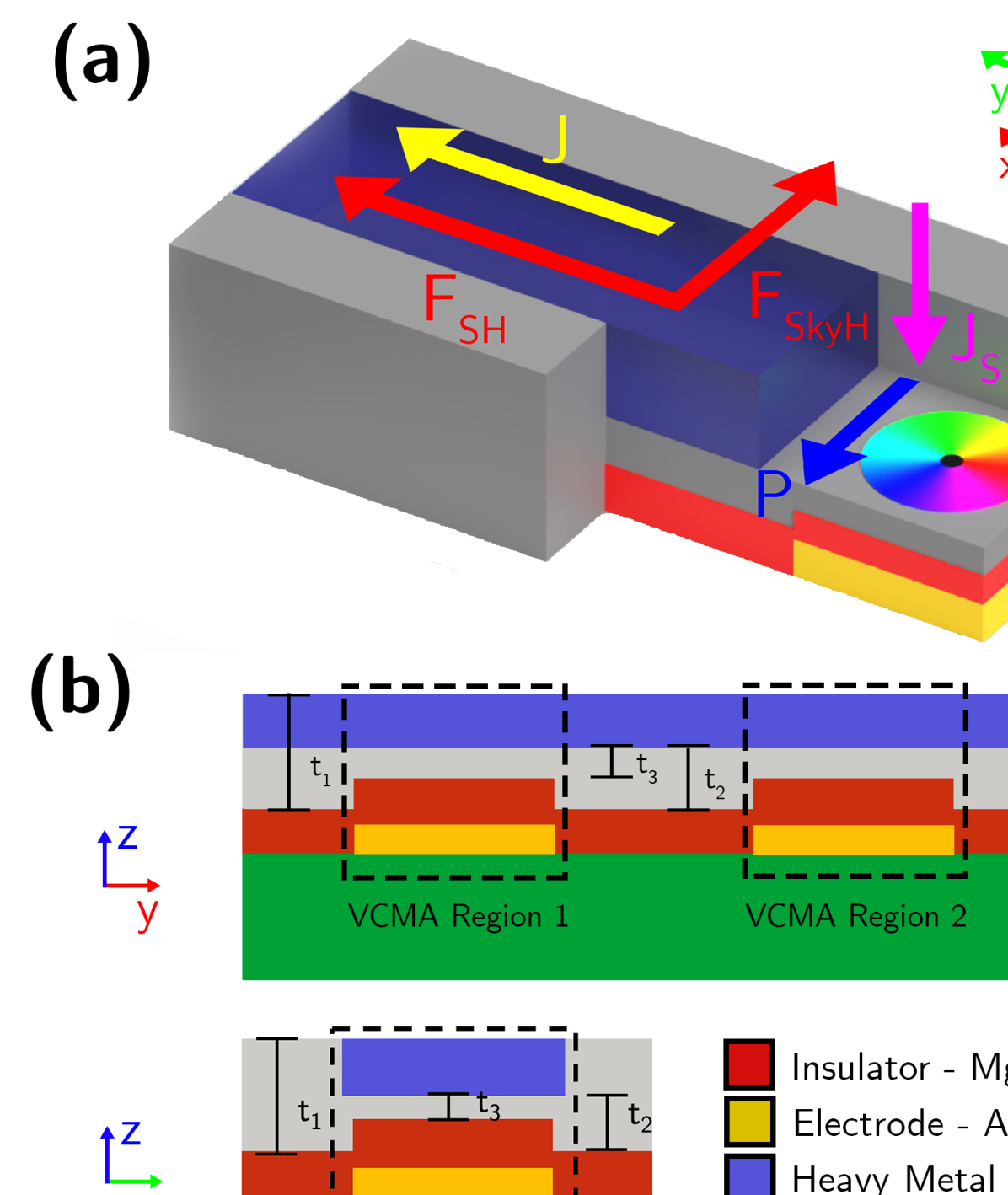
The skyrmion logic system of Ref. 12 utilizes four distinct skyrmion phenomena. As illustrated in Fig. 1(a), current injected in the direction through a ferromagnetic track creates a spin current in the direction via the spin-Hall effect. This spin current causes a first force that pushes the skyrmion in the direction. Sampaio et al. (2013); Tomasello et al. (2014) -directed skyrmion motion results in a -directed deviation from linear -directed motion via a second force due to the skyrmion-Hall effect (SkHE),Wang et al. (2018) and is countered by the third force, edge repulsion, to prevent skyrmion annihilation. The fourth phenomenon is the skyrmion-skyrmion repulsion between two skyrmions in close proximity.Wang et al. (2017)
II.2 Reversible Skyrmion Logic Gates
The skyrmion logic system of Ref. 12 enables a range of skyrmion logic gates and encodes binary ‘1’ and ‘0’ values through the presence or absence of a skyrmion, respectively. Constant injected current drives skyrmions along tracks towards logic gate junctions, where interplay between the skyrmion-Hall effect and skyrmion-skyrmion repulsion causes the skyrmion trajectories to depend on the binary states of the inputs. As illustrated by the example AND/OR gate of Supplemental Material Fig. S1 and Video S1, the logical outputs are encoded in the output tracks to which the skyrmions are driven.Chauwin et al. (2019)
In these reversible skyrmion logic systems, all information is conserved, theoretically permitting energy dissipation below the Landauer limit. Relatedly, skyrmions are never destroyed and therefore need not be nucleated, as they can be indefinitely cascaded and reused.Chauwin et al. (2019) The final outputs of this skyrmion logic system can be read via magnetic tunnel junctions. Hamamoto and Nagaosa
II.3 Notch Synchronizer
Skyrmion logic gates are cascaded by using the output skyrmions from one gate as the input skyrmions of other gates. As the gates require skyrmion synchronization to ensure proper skyrmion-skyrmion repulsion within the junctions, Ref. 12 proposed a notch synchronizer between cascaded logic gates (Supplementary Material Fig. S2 and Video S2). The notch structure pins skyrmions when normal low current density is applied, as the skyrmion radius is too large. By periodically providing a larger current pulse, the skyrmion radii shrink such that they depin and pass through the constriction.
By placing multiple synchronizers in a skyrmion logic circuit, a global clocking current pulse can force the skyrmions to interact at the track junctions, thereby ensuring correct logical operation despite thermal variations in velocity and differing trajectory lengths. However, this large current pulse is energetically expensive and can cause rapid skyrmion acceleration that can lead to skyrmion annihilation. It is also difficult to fabricate the notch structure with sufficient precision to ensure proper synchronization, and it is therefore worthwhile to consider alternative approaches.
II.4 Voltage-Controlled Magnetic Anisotropy
VCMA is a technique for varying the uniaxial anisotropy of a magnetic material via an applied electric field. A voltage applied across the ferromagnetic track changes its electron density of states which, in turn, changes the perpendicular magnetic anisotropy and magnetic coercivity.Kang et al. (2016) The relationship between applied voltage and change in anisotropy is predominantly linear, following the expression . Where is the resultant anisotropy, is the original anisotropy, is the bias voltage, and is a material-dependent coefficient ranging for most materials between and for Fe/Vacuum and Fe/MgO interfaces respectively.Wang et al. (2012)
When applied to the skyrmion track, VCMA can be used to pin a skyrmion via an anisotropy gradient.Zhang et al. (2015c) An applied positive voltage increases the anisotropy of the VCMA region which creates a positive energy barrier for a skyrmion entering the region and a negative energy barrier for a skyrmion leaving the region. For a negative voltage, the respective energy barriers are reversed.Kang et al. (2016) Skyrmions without sufficient driving force or velocity will be unable to pass, and will be pinned at the interface between the high and low anisotropy regions.
III VCMA Synchronizer
We propose the synchronization of skyrmion logic systems by periodically switching skyrmion pinning via modulation of VCMA, enabling logic circuits that are more reliable and energy-efficient than can be achieved with notch synchronizers. These VCMA synchronizers can be readily fabricated with existing technology, and their functionality has been demonstrated via micromagnetic simulation.
III.1 Structure
Fig. 1(a) and (b) shows the top and cross-sectional views of a VCMA synchronizer, respectively. The bottom electrode (Au) is coupled to the ferromagnetic racetrack (Co) via the insulator (MgO), thus allowing an electric field to be applied to the racetrack to modulate its anisotropy. and represent the track thickness and track wall, respectively. In order for skyrmions to be pinned at the VCMA region in the absence of an applied electric field, a preexisting anisotropy bias is introduced to the VCMA region by locally reducing the thickness of the track from to .Carcia (1988); Metaxas et al. (2007)
Experimentally, the proposed VCMA synchronizer can be fabricated using standard semiconductor processing techniques. Bottom electrodes and cobalt racetrack regions with different thicknesses (, , ) can be created with metal deposition, electron-beam lithography/photolithography and Ar ion milling. Chemical-mechanical polishing can be used to ensure the smoothness of the skyrmion racetrack.
III.2 Operation
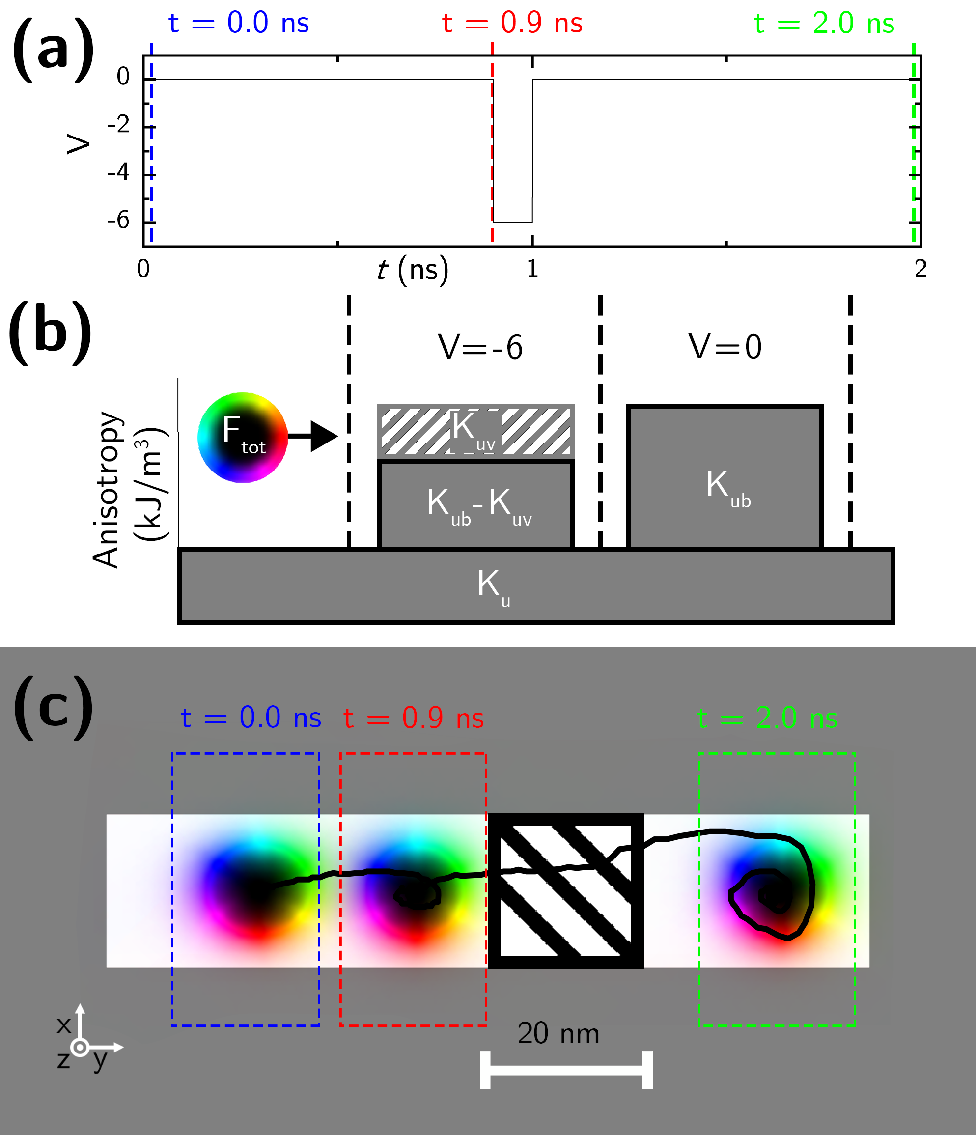
The operation of the VCMA skyrmion synchronizer is demonstrated in the micromagnetic simulation results of Fig. 2 and Video 1. A global electric current applied in the direction accelerates the skyrmion in the direction, though it is pinned by the VCMA region when a clock voltage of is applied. At ns, a clock pulse of temporarily lowers the anisotropy, depinning the skyrmion. By including numerous such VCMA regions controlled by the same global clock, skyrmions can be synchronized within large-scale cascaded skyrmion logic circuits to ensure proper skyrmion-skyrmion repulsion with the logic gates and correct logical functionality.
90% of the clock cycle remains at zero volts, which reduces the amount of leaked charge, improving static power dissipation. Additionally, as it pins skyrmions without applied voltage, the system preserves memory without power. As the VCMA synchronizer avoids the high current densities of the notch-based design, it is more dynamically power efficient. Further, as high current densities often destroy skyrmions, the VCMA synchronizer is also more reliable.
IV VCMA Synchronizer Analysis and Design
By quantifying the interaction between a moving skyrmion and the VCMA region, we can optimize the efficiency, accuracy, and speed of VCMA-clocked skyrmion logic systems. This analysis reveals that both the injected current and the velocity of the skyrmion contribute to the total effective driving force. Governed by the Thiele equation, this force determines whether a skyrmion can overcome a specified anisotropy barrier, and therefore is crucial for selecting the PMA of the VCMA region.
IV.1 Anisotropy Barrier
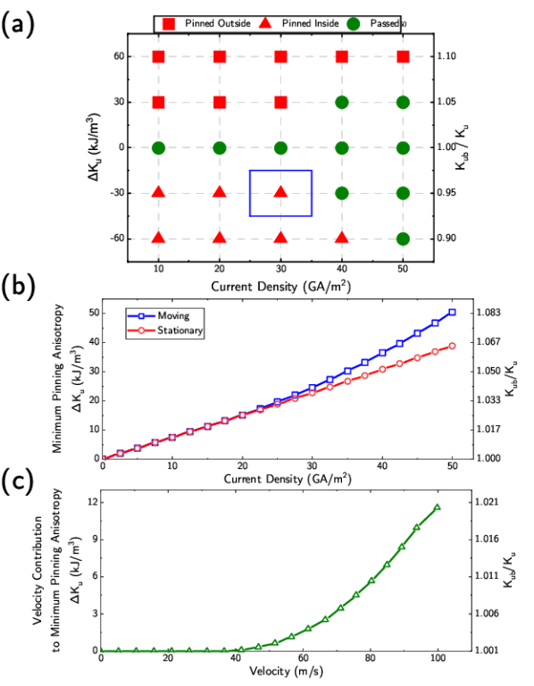
The ability of skyrmions to traverse a VCMA region was evaluated as a function of current density and anisotropy. As shown in Fig. 3(a), skyrmions are unable to pass through regions of differing anisotropy unless sufficient current is provided. When the VCMA region anisotropy is higher than the remainder of the track, skyrmions are unable to overcome the anisotropy barrier to enter the VCMA region and are pinned outside; when the VCMA region anisotropy is lower than the remainder of the track, skyrmions enter the VCMA region but are unable to traverse the barrier to leave the VCMA region and are pinned inside.

It is noteworthy that Fig. 3(a) is asymmetric about , as skyrmions with sufficient current are able to overcome larger energy barriers when leaving the VCMA region than when entering it. This is a result of the acceleration of the skyrmions as they propagate through the VCMA region, resulting in skyrmions attempting to leave the VCMA region with significantly greater velocity than when they entered the VCMA region.
This impact of velocity can be more directly observed when comparing the ability of stationary and moving skyrmions to traverse the VCMA region: all of the simulations in Fig. 3(a) were performed for both stationary skyrmions and skyrmions moving at their terminal velocity, and in one case the moving skyrmion is able to traverse the VCMA region whereas the initially stationary skyrmion is not.
IV.2 Skyrmion Dynamics
To further analyze the impact of skyrmion velocity, skyrmions were accelerated along a racetrack to determine the minimum pinning magnetic anisotropy as a function of current density. As shown in Fig. 3(b), increases in current density necessitate larger anisotropy barriers to pin the skyrmions. Furthermore, skyrmions that enter the VCMA region with zero velocity are clearly observed to overcome less of an energy barrier than skyrmions that enter the VCMA region with their terminal velocity.
The impact of skyrmion velocity on the ability of a skyrmion to traverse an anisotropy barrier is further explored in Fig. 3(c). This difference in pinning anisotropy is quadratic with respect to velocity, and it represents the contribution of the skyrmion velocity to the minimum pinning anisotropy. The cause of this increase can better understood by analyzing the Thiele equation (1) and its solution (2):Yanes Diaz et al. (2019)
| (1) |
| (2) |
Comparing the steady state solution () to the dynamic solution (), there is a ratio between steady state velocity () and dynamic velocity () equal to . These differences in velocity can be accounted for with an additional fictitious force in the direction equal to , referred to as effective velocity force (). Both the current density driving force () and the effective velocity force () contribute to the total effective driving force of the skyrmion (), and can be quantized in terms of anisotropy increase from Fig. 3(c).
Figure 4 depicts the impact of the VCMA clock pulse on the forces involved in the pinning interaction. In the absence of a clock pulse, the total force is negative, implying a transverse force in opposition to traversing the barrier; when a clock pulse is applied, the total force is positive, implying a transverse force that enables the skyrmion to traverse the barrier. To minimize the power dissipation and error rate of a skyrmion logic system, the VCMA parameters should be optimized to provide maximum reliability with minimal VCMA voltage modulation.
V Skyrmion Logic Circuits via VCMA Synchronization
The VCMA clocking can be used to synchronize the motion of all the skyrmions within a system, thereby enabling the proper functionality of large-scale cascaded circuits. To prove the ability of the proposed VCMA synchronizers to enable cascaded logic gates, their functionality has been demonstrated in pipelined AND/OR and full adder circuits via micromagnetic simulation.
V.1 Pipelined AND/OR Gate
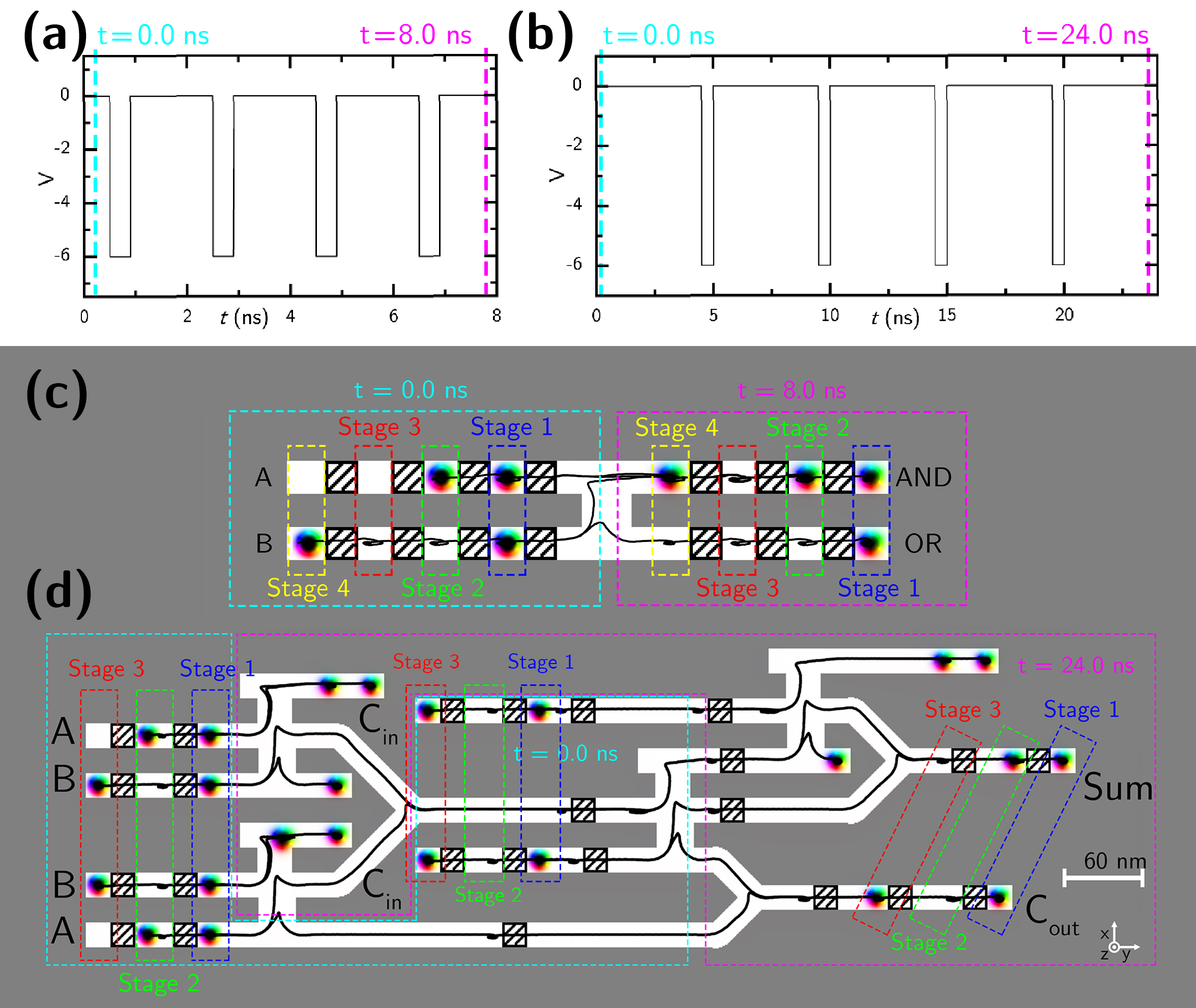
The effectiveness of the VCMA synchronizers can be demonstrated by adding pipelining to the simple AND/OR logic gate of Supplemental Material Fig. S1. As shown in Fig. 5(a), 5(c), and Video. 2, the skyrmions can be made to advance past one VCMA region during each 2 ns clock cycle, thereby providing the synchronization necessary for proper repulsion within the AND/OR gate junction. The logic gate has a throughput of one computation per clock cycle of both the AND and OR functions, and thus correctly performs computations for all four AND/OR conditions during this 8 ns simulation.
V.2 Pipelined One-Bit Full Adder
To ensure the proper functionality of cascaded skyrmion logic gates, it is critical that the skyrmions entering each logic gate junction are synchronized. As shown in Fig. 5(b), 5(d), and Video. 3, the careful addition of VCMA synchronizers to a one-bit full adder circuit ensures proper skyrmion-skyrmion interactions despite the differing lengths of the skyrmion trajectories. In particular, the VCMA synchronizers are placed such that the skyrmions arrive contemporaneously at the logic gate junctions. Like the pipelined AND/OR gate, this full adder circuit therefore produces a throughput of one full addition computation (Sum and Cout) per clock cycle (5 ns). As there are two VCMA synchronizers within the full adder computation path, the latency of this full adder is two clock cycles (10 ns).
VI Conclusion
Reversible skyrmion logic provides a potential route to compute with less energy dissipation than Landauer’s limit to the minimum energy for computation. In light of the importance of skyrmion synchronization to ensure proper skyrmion-skyrmion interactions within the logic gate junctions, this paper proposes skyrmion synchronization using VCMA modulation. We demonstrate the functionality and analyze the behavior of these VCMA synchronizers via micromagnetic simulation, providing a deeper understanding of their behavior that enables large-scale cascaded skyrmion circuit design. The use of VCMA synchronizers provides a reduced error rate and requires less energy than can be achieved with notch synchronizers,Chauwin et al. (2019) thereby greatly advancing the prospects for reversible computing with magnetic skyrmions.
The data that support the findings of this study are available from the corresponding author upon reasonable request.
Acknowledgements.
The authors thank E. Laws, J. McConnell, N. Nazir, and L. Philoon for technical support. This research is sponsored in part by the Texas Analog Center of Excellence Internship Program.References
- Everschor-Sitte et al. (2018) K. Everschor-Sitte, J. Masell, R. M. Reeve, and M. Kläui, Journal of Applied Physics 124, 240901 (2018).
- Sampaio et al. (2013) J. Sampaio, V. Cros, S. Rohart, A. Thiaville, and A. Fert, Nature Nanotechnology 8, 839 (2013).
- Tomasello et al. (2014) R. Tomasello, E. Martinez, R. Zivieri, L. Torres, M. Carpentieri, and G. Finocchio, Scientific Reports 4, 6784 (2014).
- Kang et al. (2018) W. Kang, X. Chen, D. Zhu, S. Li, Y. Huang, Y. Zhang, and W. Zhao, Design, Automation & Test in Europe Conference & Exhibition (2018).
- (5) A. K. Behera, C. Murapaka, S. Mallick, B. B. Singh, and S. Bedanta, “Skyrmion racetrack memory with an antidot,” arXiv:1907.03449 [cond-mat.mtrl-sci] (2020) .
- Zhang et al. (2015a) X. Zhang, G. P. Zhao, H. Fangohr, J. P. Liu, W. X. Xia, J. Xia, and F. J. Morvan, Scientific Reports 5, 7643 (2015a).
- Zhang et al. (2015b) S. Zhang, A. A. Baker, S. Komineas, and T. Hesjedal, Scientific Reports 5, 15773 (2015b).
- Zhang et al. (2015c) X. Zhang, Y. Zhou, M. Ezawa, G. P. Zhao, and W. Zhao, Scientific Reports 5, 11369 (2015c).
- Xing et al. (2016) X. Xing, P. W. T. Pong, and Y. Zhou, Phys. Rev. B 94, 054408 (2016).
- Luo et al. (2018) S. Luo, M. Song, X. Li, Y. Zhang, J. Hong, X. Yang, X. Zou, N. Xu, and L. You, Nano Letters 18, 1180 (2018).
- Zhang et al. (2015d) X. Zhang, M. Ezawa, and Y. Zhou, Scientific Reports 5, 9400 (2015d).
- Chauwin et al. (2019) M. Chauwin, X. Hu, F. Garcia-Sanchez, N. Betrabet, A. Paler, C. Moutafis, and J. S. Friedman, Phys. Rev. Applied 12, 064053 (2019).
- Wang et al. (2018) J. Wang, J. Xia, X. Zhang, G. P. Zhao, L. Ye, J. Wu, Y. Xu, W. Zhao, Z. Zou, and Y. Zhou, Journal of Physics D: Applied Physics 51, 205002 (2018).
- Wang et al. (2017) X. Wang, W. Gan, J. Martinez, T. Funan, M. Jalil, and W. S. Lew, Nanoscale 10 (2017), 10.1039/C7NR06482A.
- (15) K. Hamamoto and N. Nagaosa, “Electrical detection of a skyrmion in a magnetic tunneling junction,” arXiv:1803.04588 [cond-mat.mes-hall] (2018) .
- Kang et al. (2016) W. Kang, Y. Huang, C. Zheng, W. Lv, N. Lei, Y. Zhang, X. Zhang, Y. Zhou, and W. Zhao, Scientific Reports 6, 23164 (2016).
- Wang et al. (2012) W.-G. Wang, M. Li, S. Hageman, and C. L. Chien, Nature Materials 11, 64 (2012).
- Vansteenkiste et al. (2014) A. Vansteenkiste, J. Leliaert, M. Dvornik, M. Helsen, F. Garcia-Sanchez, and B. Van Waeyenberge, AIP Advances 4, 107133 (2014).
- Carcia (1988) P. F. Carcia, Journal of Applied Physics 63, 5066 (1988).
- Metaxas et al. (2007) P. J. Metaxas, J. P. Jamet, A. Mougin, M. Cormier, J. Ferré, V. Baltz, B. Rodmacq, B. Dieny, and R. L. Stamps, Phys. Rev. Lett. 99, 217208 (2007).
- Yanes Diaz et al. (2019) R. Yanes Diaz, F. Garcia-Sanchez, R. Luis, E. Martinez, V. Raposo, L. Torres, and L. Lopez-Diaz, Applied Physics Letters 115, 132401 (2019).