- CSS
- chirp spread spectrum
- SER
- symbol error ratio
- SNR
- signal-to-noise ratio
- LoRa
- Long-Range
- IoT
- Internet of things
- FSK
- frequency shift keying
- AWGN
- additive white Gaussian noise
- LPWAN
- low power wide area network
- PHY
- physical layer
- SE
- spectral efficiency
- EE
- energy efficiency
- MLD
- maximum likelihood detection
- DSSS
- direct sequence
- FHSS
- frequency hoping
- FFT
- fast Fourier transform
- SF
- spreading factor
- IQCSS
- in-phase and quadrature chirp spread spectrum
- MLE
- maximum likelihood estimator
- DFT
- discrete Fourier transform
- SFD
- start frame delimeter
- GSM
- Global System for Mobile Communications
- DCRK-CSS
- discrete chirp rate keying CSS
- CP
- cyclic prefix
- LS
- least squares
Alternative Chirp Spread Spectrum Techniques for LPWANs
Abstract
Chirp spread spectrum (CSS) is the modulation technique currently employed by Long-Range (LoRa), which is one of the most prominent Internet of things wireless communications standards. The LoRa physical layer (PHY) employs CSS on top of a variant of frequency shift keying, and non-coherent detection is employed at the receiver. While it offers a good trade-off among coverage, data rate and device simplicity, its maximum achievable data rate is still a limiting factor for some applications. Moreover, the current LoRa standard does not fully exploit the CSS generic case, i.e., when data to be transmitted is encoded in different waveform parameters. Therefore, the goal of this paper is to investigate the performance of CSS while exploring different parameter settings aiming to increase the maximum achievable throughput, and hence increase spectral efficiency. Moreover, coherent and non-coherent reception algorithm design is presented under the framework of maximum likelihood estimation. For the practical receiver design, the formulation of a channel estimation technique is also presented. The performance evaluation of the different variants of CSS is carried out by inspection of the symbol error ratio as a function of the signal-to-noise ratio together with the maximum achievable throughput each scheme can achieve.
Index Terms:
Chirp spread spectrum, long-range communications, LPWAN, IoT, wireless communications.I Introduction
Recently, a lot of attention has been drawn towards long-range and low-power consuming wireless communication schemes [1]. Long-Range (LoRa) is a wireless communication protocol that has got preference among the schemes considered primary for Internet of things (IoT) applications [2]. The main application of LoRa, and low power wide area networks in general, is to provide connectivity for mobile and stationary wireless end-devices that require data rates in the order of tens of kbps up to a few Mbps within a coverage area up to tens of kilometers. For maximization battery life and minimizing end-device costs, low energy consumption and simple transceiver design are also desirable characteristics for LPWANs devices [3].
The physical layer (PHY) of LoRa has gained considerable attention within the academic community, and several papers have been published with investigations on the characteristics of LoRa PHY and MAC schemes [4, 5]. Its modulation scheme is based on chirp spread spectrum (CSS) in conjunction with frequency shift keying (FSK). Some authors have proposed enhancements to the LoRa PHY framework. For instance, encoding extra information bits on the phase of the spreading chirp waveform has been proposed in [6], and similar work employs pulse shaping on top of the chirp waveform to reduce the guard-band, and thus increases the number of channels within the available frequency band [7]. Most recently, an approach that uses the chirp rate to carry one extra information bit has been proposed in [8]. A combination of pulse position modulation with CSS has been proposed in [9], where the orthogonality among time shifted versions of the chirp signal is exploited to allow multiple access in the downlink. Moreover, the analysis of inter-spreading factor in LoRa systems has been investigated in [10] and [11], showing that the symbol error rate increases significantly in high signal-to-interference ratios. The robustness against interference of the schemes presented here can be investigated in the future. While in [12], the performance of the LoRa PHY is compared against a frequency hopping technique, and results present that LoRa has a higher transmission success probability for small data packets. Therefore, inspired by the aforementioned works, and departing from the LoRa PHY framework, we propose a more broad scheme that encodes multiple information bits on the discrete chirp rate. The scheme proposed in [13] is revisited here, and while it employs coherent detection, the new scheme that exploits the chirp rate as information carrier is able to benefit from non-coherent detection when operating over flat-fading channels. The main goal of this paper is to present two innovative modulation designs that improve the current LoRa PHY, while one of them is build upon a coherent receiver, the other is build based on a non-coherent receiver. Furthermore, maximum likelihood estimation for the transmitted data symbols using the classical CSS transceiver is presented.
The main contributions contained in this paper are:
-
•
A detailed transceiver description of two proposed modulation techniques based on CSS, namely in-phase and quadrature chirp spread spectrum (IQCSS) and discrete chirp rate keying CSS (DCRK-CSS), which are able to increase spectral efficiency (SE) and energy efficiency (EE) when compared to the conventional LoRa PHY scheme.
-
•
A mathematical derivation of the optimum receiver for CSS under the framework of maximum likelihood estimation.
- •
The remainder of the paper is organized as follows: Section II-A presents the mathematical foundations of discrete-time chirp signals from its continuous-time definition, while Sections II-B and II-C present the transmission and reception of CSS modulation under the framework of maximum likelihood estimation. Section III contains a detailed description of the transceivers which employ variants of CSS. Firstly in III-A, the LoRa PHY standard [14], subsequently in III-B the recently proposed IQCSS [13], and lastly in III-C the proposed DCRK-CSS are presented. Section IV investigates the performance of the proposed schemes under different wireless channel models. Finally, the paper is concluded in Section V with future insights, and directions on the topic of LPWANs.
II Chirp Spread Spectrum Maximum Likelihood Estimation
II-A The Chirp Signal
This subsection aims to give an analytical description of the chirp signal. In CSS, as well as in other spread spectrum techniques, such as direct sequence (DSSS) and frequency hoping (FHSS), the information is transmitted using a bandwidth much larger than required for a given data rate, i.e., the information signal is spread over the bandwidth to benefit from spreading gain. Particularly in CSS, multiplication by a chirp signal is responsible for the energy spreading in frequency [15, 16]. The linear-chirp refers to the frequency variation of the signal, which increases linearly with time.
The chirp waveform can be described by
| (1) |
where , i.e., a quadratic function of time. The signal instantaneous frequency is defined as
| (2) |
which shows that the frequency varies linearly with time. Moreover, the chirp rate is defined as the second derivative of w.r.t. as
| (3) |
The up-chirp corresponds to the case where , and the down-chirp when .
Let (Hz) represent the bandwidth occupied by the chirp signal. The signal frequency varies linearly between and within the time duration (s). If the term and , the resulting waveform is the raw chirp with starting frequency and end frequency . Conversely, if , the complex exponential is obtained. Sampling (1) at the Nyquist rate, i.e., , where (s) is sampling time interval, the baseband discrete-time chirp signal is given by
| (4) |
where is the total number of samples within seconds. Setting , and , the discrete-time raw up-chirp becomes
| (5) |
where represents the discrete chirp rate.
II-B CSS Modulation
At the transmitter side, the discrete-time chirp signal is used for spreading the information signal within the bandwidth via multiplication. The transmit signal can be described as
| (6) |
where the complex exponential term has its frequency depending upon the data symbol , which is obtained from a bit-word as
| (7) |
where the spreading factor (SF) represents the amount of bits in each bit-word. Note that each waveform has samples for having distinguishable waveforms. The data symbols are integer values from the set , which contains elements. represents the signal energy.
To explore alternative ways of generating the transmit signal, let us analyze the period of the raw up-chirp, and for the sake of brevity let us assume . Then,
| (8) |
where the terms and equal the unity for all and . Therefore, the raw up-chirp has period , and the LoRa transmit signal can be readily obtained via a discrete circular time shift operation. Hence, (6) can also be written as
| (9) |
where represents the circular shift. This equation presents simplified generation complexity when compared to (6), since it is necessary to just store one vector corresponding to the raw up-chirp and read it circularly.
II-C Maximum Likelihood Estimation of CSS
The discrete-time complex-valued received signal after synchronization can be described as
| (10) |
where represents the equivalent channel function, and is assumed to be additive white Gaussian noise (AWGN) with zero mean and variance.
Assuming knowledge of the equivalent channel function, the maximum likelihood estimator (MLE) for the transmitted data symbol is given as
| (11) |
II-C1 AWGN Channel
Under pure AWGN channel the equivalent function is the identity, i.e., , and
| (12) |
where and denote the conjugate and real part extraction operators, respectively, and note that . Consequently, (11) can be modified to
| (13) |
By inspecting the maximization problem in (13), one can see that the demodulation process can be efficiently executed by firstly multiplying the received signal with the conjugated raw up-chirp, hereafter named down-chirp, secondly computing the discrete Fourier transform (DFT) of this result, and thirdly selecting the frequency bin that maximizes the real part of the compound result. Luckily, this operation can be efficiently carried via the fast Fourier transform (FFT) algorithm. Therefore, the MLE for the transmitted data symbol is given by
| (14) |
where , , and the DFT operator.
II-C2 Flat-fading Channel
Assuming a flat fading wireless channel, the equivalent channel function becomes , where denotes a complex-valued gain. If a channel estimation mechanism is available at the receiver side, coherent detection can be employed, and by following the same path that led to (14), the estimated data symbol can be obtained as
| (15) |
where , . However, if non-coherent detection is implemented at the receiver, the random phase rotation induced by the complex channel gain cannot be reverted, and (15) can be modified to
| (16) |
II-C3 Frequency Selective Channel
Under frequency selective channel, , where represents the discrete-time channel impulse response that contains complex-valued taps. Assuming that channel estimation is available at the receiver, the estimated data symbols can be obtained from (11) by implementing a search over . However, in order to derive a low complexity solution from (11), one needs to assume that a cyclic prefix (CP) is appended to the beginning of the transmit signal, and , where is the length of the CP in samples. Here, a vector notation is adopted for the sake of simplicity. Let be the circulant channel matrix obtained from , and represent vectors whose entries are the samples from and , respectively. Thus, the estimated data symbol can be obtained by
| (17) |
where , and is the Hermitian operator. Note that the channel matrix can be estimated at the receiver by transmitting known sequences.
III CSS-based Modulation Schemes
III-A LoRa Physical Layer
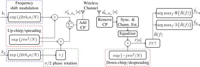
The use of CSS in the LoRa wide area network standard is a recent and successful example of employment of chirp signals to wireless communications. Notably, LoRa’s PHY employs CSS in conjunction with a variant of FSK modulation as described above [14, 17]. It is important to note that in this case, the discrete chirp rate is set to the unity, and the receiver employs non-coherent detection. Moreover, LoRa PHY defines the SF as the amount of bits that one symbol carriers, which ranges from 6 to 12 bits. In short, Fig. 1 presents the discrete-time baseband LoRa PHY transceiver block diagram. The bit-word contains SF bits that are mapped into one symbol , which feeds the CSS modulator. The despreading operation at the receiver side is accomplished by multiplying the received signal with a down-chirp, which is obtained by conjugating the up-chirp signal. At the receiver side, the estimated data symbol is obtained by selecting the frequency index with maximum value.
The spreading gain, also known as processing gain, is defined by the ratio between the bandwidths of the spreading signal and of the information signal, and for LoRa’s PHY it can be defined in dB as
| (18) |
and as , the SF also directly relates to the performance improvement observed with a spread spectrum system when compared to a non-spread system. This is analogous to the performance enhancement achieved via coding schemes. Larger SFs correspond to lower code rates, and the improvement obtained comes at the cost of reduced data rate. Therefore, the SF is used as adaptive modulation parameter depending on the signal-to-noise ratio (SNR), and consequently larger SFs allow longer coverage ranges with reduced data rates.
A key aspect of LoRa PHY is the fact that channel estimation and equalization are not necessary, since it employs the non-coherent detection receiver. However, employing coherent detection will improve the EE performance of LoRa, since the imaginary noise component is not taken in the estimation of the received data symbol. Furthermore, under harsher multi-tap, i.e., frequency selective, channel conditions the original LoRa modulation performance can degrade significantly, as also observed in [18].

III-B In-phase and Quadrature CSS
In IQCSS, information is encoded in both in-phase (real) and quadrature (imaginary) components of the transmit signal [13]. By making use of the orthogonality between the sine and cosine waves it is possible to transmit simultaneously two data symbols. Its transmit signal is given by
| (19) |
where
| (20) |
where and are independent identically (uniform) distributed data symbols drawn from , and each carries bits. Thus, the total amount of transmitted bits is doubled when compared to the LoRa PHY specification.
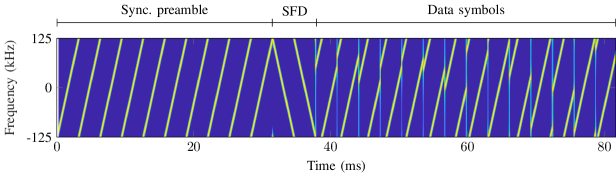
Fig. 3 illustrates the discrete-time baseband IQCSS transceiver block diagram. Note that the additional operations performed at the receiver side do not require modifications on the LoRa’s transmit signal structure, since IQCSS makes use of the already available synchronization preamble for channel estimation and subsequent coherent detection. Fig. 2 illustrates one LoRa PHY packet, where there are 14 modulated chirps in the data payload, 10 up-chirps are available for synchronization, followed by 2 down-chirps that indicate the beginning of the data symbols, and are named start frame delimeter (SFD) [14].
The received signal after equalization and despreading is given by
| (21) |
where and the received data symbols are given by
| (22) |
| (23) |
where .
It is important to point out that IQCSS requires coherent detection to work. Therefore, for making further use of the information carried with the synchronization preamble, we propose to use the least squares (LS) approach for estimating the channel gain using the already available preamble structure for synchronization.
Assuming that the channel presents flat-fading within its bandwidth, the received preamble can be written as
| (24) |
where represents the 10 up-chirps transmitted at the beginning of the LoRa PHY packet, is AWGN with zero mean and variance, and is the complex-valued channel gain. Consequently, the LS error criterion, which is the squared difference between the received data and the signal model [19], is given by
| (25) |
where is the preamble length in samples. Differentiating (25) w.r.t. , and setting the result to zero yields to
| (26) |
where and are vectors whose entries are the samples from and , respectively, and is the estimated channel gain.
For the case of frequency selective channels, the received preamble is given by
| (27) |
where represents the discrete-time channel impulse response with taps. Under the assumption of a CP appended to the beginning of each chirp, the linear convolution in (27) becomes circular. Thus, after CP removal, the -th received chirp from the preamble can be written in matrix form as
| (28) |
where contains the samples from the -th up-chirp in the synchronization preamble. Moreover, considering the commutative property of the convolution, (28) can be reformulated as
| (29) |
where is a circulant matrix obtained from one raw up-chirp, and contains the channel impulse response in its first entries. Therefore, the LS approach can be extended to frequency selective channels. However, as mentioned, a CP needs to be added to the preamble chirps, thus modifying the original LoRa PHY signal structure. Similarly to (25), the LS error criterion can be written as
| (30) |
Differentiating (30) w.r.t. , setting the result to zero, and solving for yields the LS estimator of the channel impulse response as
| (31) |
where contains the estimated channel impulse response, and we define
| (32) |
as a vector whose entries are the averaged samples over the received synchronization chirps after CP removal. This allows noise reduction, since all chirps in the preamble are used for estimating the channel. Note that up-chirps following the LoRa PHY structure. It is important to note that, has in total entries, but only the first are used as an estimate of the channel taps. Furthermore, by inspecting (31), one can see that is an orthogonal matrix, and the estimator simplifies to
| (33) |
which reduces considerably the estimation computational complexity.
Assuming that the channel estimation and equalization modules are available at the receiver, coherent detection can be made possible. In this case, the receiver structure allows greater SE and EE when compared with LoRa modulation. Nevertheless, if these modules are not used, the receiver structure is equivalent to the LoRa standard. Therefore, the receiving devices (gateways) that operate using IQCSS can still decode the information transmitted using the original LoRa modulation, thus making IQCSS gateways backwards compatible.
III-C Discrete Chirp Rate Keying CSS
While IQCSS is able to increase the data throughput by exploiting the benefits of a coherent detection receiver, it is also possible to encode extra information bits on the discrete chirp rate and maintain simpler non-coherent detection. A similar approach is has been proposed in [8]. However, this approach is limited to only one extra information bit. Hence, we propose to extend this framework to multiple extra information bits. Hereafter, we refer to this scheme as DCRK-CSS.
Let denote the bit-word that will modulate the chirp rate, where represents the amount of extra bits encoded, and denote the bit-word that will modulate the frequency of a complex exponential, is equivalent to LoRa’s spreading factor. The total amount of possible chirp rates is given by . Therefore, the data symbol is comprised by both bit words, i.e., .
The discrete chirp rate is selected depending upon the combination a of bits in , e.g., for bits, the defined chirp rates are given by
| (34) |
where assumes non-zero integer values, and is an indexing variable. The transmit signal can be written as
| (35) |
where .
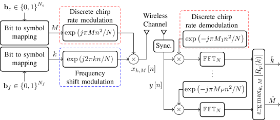
Fig. 4 illustrates the discrete-time baseband transceiver block diagram. The received signal after synchronization goes through a bank of dechirping modules with different chirp rates. Let the DFTs of despreaded signals be represented by
| (36) |
where considering transmission over a flat fading channel. The estimated frequency, and chirp encoded data symbols are jointly obtained as
| (37) |
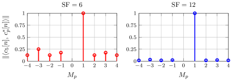
It is important to note that the spreading chirps with different rates are not orthogonal, but they present low correlation, and the performance loss due to intrinsic interference becomes negligible. Furthermore, the level of intrinsic interference is inversely proportional to , such that smaller SFs are subject to more performance loss. To better illustrate this characteristic, Fig. 5 shows the absolute value of the inner product between and the despreading signals defined by
| (38) |
IV Performance Analysis
For comparing the performance of the proposed schemes against the LoRa PHY, we resort to numerical simulations for estimating the symbol bit error ratio (SER/BER) under three different wireless channel models, namely AWGN, time-variant (TV) non-frequency-selective (Rayleigh) channel, and time-variant frequency-selective (TVFS). For the latter, the channel model chosen is ”Typical case for urban area” with 12 taps [20]. This has been chosen due to the similar operating frequency and bandwidth of LoRa and Global System for Mobile Communications (GSM) in Europe. Moreover, based on the symbol error ratio, the maximum achievable throughput is also presented for supporting the claims of increased spectral efficiency.
Table I shows the simulation parameters considered.
| Parameter | Value |
| Spreading factor | |
| Extra information bits | |
| Bandwidth | 250 kHz |
| Carrier frequency | 863 MHz |
| Mobile speed | 3 km/h |
| CP length | 16 samples |
| TV channel | single tap (Rayleigh) |
| TVFS channel | 12 taps ”Typical case for urban area” [20] |
| Data frame size | 30 chirps |
| Preamble frame size | 10 up chirps + 2 down chirps |
IV-A Symbol and Bit Error Ratio Analysis
IV-A1 AWGN Channel
Fig. 6(a) shows the estimated BER under AWGN channel for LoRa, IQCSS and DCRK-CSS. Note that IQCSS transmits twice the amount of bits when compared with LoRa, and DCRK-CSS transmits extra bits. Larger SFs will result in better performance, since all schemes transmit data using frequency modulation, and adding more symbols to the constellation does not reduce the minimum symbol distance. There is a gap of about 0.5 dB between the curves of IQCSS and LoRa for the same SF, whereas between LoRa and DCRK-CSS the gap increases with . The gap between LoRa and IQCSS is observed because IQCSS collects less noise than LoRa in the process of detection, since it explores the phase information instead of making a decision based solely on the estimated energy of the frequency bins. Thus, one can use less energy to transmit more information with the same bit error probability when employing IQCSS over LoRa. However, the gap between LoRa and DCRK-CSS is observed due to the smaller average energy bit required to maintain an equal BER, and this gap increases as the number of extra bits encoded on the chirp slope increases. Nevertheless, note that for the lower regime, the gap is reduced when compared with the high regime, this is observed since the different despreading signals are not completely orthogonal to each other, but rather present a significant low correlation.
Fig. 6(b) also shows SER under AWGN channel while taking into consideration the spreading gain. The transmit power available is divided between the in-phase and quadrature components for IQCSS, while in LoRa and DCRK-CSS all power is used for a single component. Therefore, there is a 3 dB gap between LoRa and IQCSS in Fig. 6(b). Moreover, there is small gap between LoRa and DCRK-CSS, which is present due to the intrinsic interference caused by the non-orthogonality between the different despreading signals. As we can see, the performance degradation is acceptable for the increased throughput provided by DCRK-CSS. It is also important to point out that for larger SFs, the this gap is reduced, since the intrinsic interference is reduced as the SF increases.
In order to quantize the advantages with respect to the maximum throughput achievable by the presented schemes, Fig. 7 presents the maximum achievable throughput under AWGN channel. The Shannon channel capacity is also plotted for reference. IQCSS achieves more than double the maximum throughput of LoRa, since it encodes double the amount of bits, and it benefits from coherent detection at the receiver. DCRK-CSS is also able to increase the maximum throughput when compared to the LoRa PHY scheme. The effective throughput (bps) is calculated as
| (39) |
where represents the number of bits carried by each modulation scheme. Considering , there is an increase on the throughput when comparing DCRK-CSS with LoRa of 16.6% and 25% for and bits, respectively. Comparatively, for there is an increase of 33.3% and 50% for and , respectively. Therefore, both IQCSS and DCRK-CSS make a more efficient usage of spectrum resources. These are key aspects required for more data demanding IoT applications.
The energy efficiency of the modulation schemes can be indirectly demonstrated via Fig. 6(a). However, this figure does not show how much of the energy is used to transmit bits that are correctly received. Therefore, Fig. 8 presents the energy that is required to transmit with a certain bit error rate for the different modulation schemes. The effective energy per useful bits is defined as
| (40) |
By inspecting the result in Fig. 8, smaller SFs are less energy efficient because they are less robust to bit errors, and as more bits are transmitted with the alternative schemes, the effective energy required to transmit with a certain bit error ratio is reduced when compared to the original LoRa.
IV-A2 Flat Fading Channel
Fig. 9 and Fig. 10 show respectively the estimated BER and SER under time-variant flat fading channel. The same behavior observed under AWGN channel regarding the performance gaps can be observed between LoRa and DCRK-CSS. Moreover, there are three BER and SER curves for accessing IQCSS’s performance. The solid curves with circle marks represents the BER considering an unrealistic scenario where the channel coefficient is known at the receiver, i.e., this represents the baseline performance. Assuming that the channel coefficient remains static during the transmission of one frame, which has 10 chirps for synchronization and channel estimation, and 30 chirps encoded with information, the dashed curves with asterisk marks (Est. chan.1) are obtained. These results show that the proposed channel estimation technique yields performance comparable to perfect channel estimation in cases where the channel complex gain does not change during the transmission of frame. Lastly, the dot dashed curves with x marks (Est. chan.2) represent the case where the channel coefficient changes during the transmission of one frame. In this last case, we consider that the relative speed between transmitter and receiver is 3 km/h, carrier frequency is 863 MHz, the bandwidth occupied is 250 kHz. As a result from the mobility, IQCSS suffers a performance degradation when compared with LoRa and DCRK-CSS. However, considering a low mobility scenario, this degradation might be neglected. For this particular simulation scenario, significant performance degradation is observed for SFs greater than 10.
IV-A3 Frequency Selective Channel
Fig. 11 shows the BER under the GSM channel model. Due to multipath components of the channel, the DFT output from LoRa’s and DCRK-CSS’s receivers will present multiple peaks, and depending on the channel realization, LoRa’s receiver is not able to distinguish between them, but still presents a certain level of robustness. As we can see, the performance of these two schemes degrades significantly under channels with long power delay profiles. However, IQCSS is able to deal with harsher multipath channels due to its more sophisticated receiver structure. Two curves are presented for accessing IQCSS’s performance under TVFS channels. The solid curve with circle marks is obtained considering noiseless channel estimation, whereas the dot dashed curve with x marks represents realistic case, and both use the LS channel estimation given by (33). As one can see, with LS channel estimation the BER performance approaches the case of ideal channel estimation. An error floor is present, since the channel impulse response changes within the frame duration. Hence, the smaller SFs present better performance due to its shorter time duration. The mobility scenario is considered for all curves presented in Fig. 11. For reference, a CP with length samples has been employed with IQCSS.
From the performance analysis presented, one can conclude that employing IQCSS in conditions where the wireless channel response remains static during the transmission of a data frame, and employing DCRK-CSS when it does not present significant frequency selectivity, would be advantageous for increasing the data throughput without sacrificing energy efficiency. Hence, for increasing the spectral efficiency in conditions where high mobility of the transmitting units is more likely to occur when compared to frequency selectivity, DCRK-CSS is a valid alternative to the LoRa PHY scheme. Moreover, both receivers from IQCSS and DCRK-CSS are designed to be backwards compatible with the current LoRa standard.
It is also important to point-out that the investigation shown above considers that all modulation schemes operate with the same transmission power. For the sporadic transmission of a large amount of PHY data packets, the transmitting module of the device will be operating for shorter periods of time, since IQCSS and DCRK-CSS can transmit more data per unit of time when compared to LoRa. Therefore, energy saving and longer battery life can be achieved with the proposed schemes. However, an in-depth analysis of such gains is out of the scope of this paper.
V Conclusion
This paper has presented and studied novel modulation schemes inspired by the LoRa PHY for wireless applications that require low energy consumption and enhanced spectral efficiency. The major advantage of IQCSS lies in the ability to double the SE, and at the same time to improve EE when compared with the conventional CSS employed by LoRa when employing coherent detection at the receiver side. An estimation framework that uses the synchronization preamble defined by LoRa PHY to estimated the complex-valued channel gain, in flat fading channels, and an extended framework for frequency selective channels have also been presented. On the condition of flat fading channels, the throughput can be enhanced by encoding extra information bits on the discrete chirp rate. DCRK-CSS is able to enhance SE while maintaining the benefits of non-coherent detection.
A key aspect of IQCSS and DCRK-CSS is that their receivers are still able to decode the information transmitted using the original LoRa modulation. Hence, gateways designed to operate with either are backwards compatible with the conventional LoRa. Therefore, the investigations shown in this paper have demonstrated the potential of DCRK-CSS and IQCSS as solutions for enhancing the operation of LPWAN. Nevertheless, a study on the performance of the presented modulation techniques in conjunction with channel coding remains as an interesting topic to pursue.
Acknowledgment
This research was supported by the European Union under the iNGENIOUS project, by DAAD, MESRI, and MEAE under the PROCOPE 2020 project, and by the CY Initiative through the ASIA Chair of Excellence under Grant PIA/ANR-16-IDEX-0008
References
- [1] J. Sanchez-Gomez, R. Sanchez-Iborra, and A. Skarmeta, “Transmission technologies comparison for IoT communications in smart-cities,” in GLOBECOM 2017 - 2017 IEEE Global Communications Conference, pp. 1–6, Dec 2017.
- [2] J. P. S. Sundaram, W. Du, and Z. Zhao, “A survey on LoRa networking: Research problems, current solutions and open issues,” IEEE Communications Surveys Tutorials, pp. 1–1, 2019.
- [3] A. Al-Fuqaha, M. Guizani, M. Mohammadi, M. Aledhari, and M. Ayyash, “Internet of things: A survey on enabling technologies, protocols, and applications,” IEEE Communications Surveys Tutorials, vol. 17, pp. 2347–2376, Fourthquarter 2015.
- [4] F. Adelantado, X. Vilajosana, P. Tuset-Peiro, B. Martinez, J. Melia-Segui, and T. Watteyne, “Understanding the limits of LoRaWAN,” IEEE Communications Magazine, vol. 55, pp. 34–40, Sep. 2017.
- [5] R. Fernandes, R. Oliveira, M. Luís, and S. Sargento, “On the real capacity of LoRa networks: The impact of non-destructive communications,” IEEE Communications Letters, vol. 23, pp. 2437–2441, Dec 2019.
- [6] R. Bomfin, M. Chafii, and G. Fettweis, “A novel modulation for iot: Psk-lora,” in 2019 IEEE 89th Vehicular Technology Conference (VTC2019-Spring), pp. 1–5, April 2019.
- [7] T. T. Nguyen, H. H. Nguyen, R. Barton, and P. Grossetete, “Efficient design of chirp spread spectrum modulation for low-power wide-area networks,” IEEE Internet of Things Journal, vol. 6, pp. 9503–9515, Dec 2019.
- [8] M. Hanif and H. H. Nguyen, “Slope-shift keying lora-based modulation,” IEEE Internet of Things Journal, vol. 8, no. 1, pp. 211–221, 2021.
- [9] A. Knapp and L. Pap, “Performance analysis of pulse position based chirp spread spectrum technique for multiple access,” in 2017 25th International Conference on Software, Telecommunications and Computer Networks (SoftCOM), pp. 1–5, 2017.
- [10] A. Mahmood, E. Sisinni, L. Guntupalli, R. Rondón, S. A. Hassan, and M. Gidlund, “Scalability analysis of a lora network under imperfect orthogonality,” IEEE Transactions on Industrial Informatics, vol. 15, no. 3, pp. 1425–1436, 2019.
- [11] D. Croce, M. Gucciardo, S. Mangione, G. Santaromita, and I. Tinnirello, “Impact of LoRa imperfect orthogonality: Analysis of link-level performance,” IEEE Communications Letters, vol. 22, pp. 796–799, April 2018.
- [12] M. El-Aasser, A. Gasser, M. Ashour, and T. Elshabrawy, “Performance analysis comparison between lora and frequency hopping-based lpwan,” in 2019 IEEE Global Conference on Internet of Things (GCIoT), pp. 1–6, 2019.
- [13] I. Bizon Franco de Almeida, M. Chafii, A. Nimr, and G. P. Fettweis, “In-phase and quadrature chirp spread spectrum for IoT communications,” in 2020 IEEE Global Communications Conference: Selected Areas in Communications: Internet of Things and Smart Connected Communities (Globecom2020 SAC IoTSCC), (Taipei, Taiwan), Dec. 2020.
- [14] Semtech Corporation, SX1272/73 - 860 MHz to 1020 MHz Low Power Long Range Transceiver Datasheet, January, 2019.
- [15] A. Springer, W. Gugler, M. Huemer, L. Reindl, C. C. W. Ruppel, and R. Weigel, “Spread spectrum communications using chirp signals,” in IEEE/AFCEA EUROCOMM 2000. Information Systems for Enhanced Public Safety and Security (Cat. No.00EX405), pp. 166–170, May 2000.
- [16] J. R. Klauder, A. C. Price, S. Darlington, and W. J. Albersheim, “The theory and design of chirp radars,” The Bell System Technical Journal, vol. 39, no. 4, pp. 745–808, 1960.
- [17] L. Vangelista, “Frequency shift chirp modulation: The lora modulation,” IEEE Signal Processing Letters, vol. 24, pp. 1818–1821, Dec 2017.
- [18] J. C. Liando, A. Gamage, A. W. Tengourtius, and M. Li, “Known and unknown facts of lora: Experiences from a large-scale measurement study,” ACM Trans. Sen. Netw., vol. 15, Feb. 2019.
- [19] S. M. Kay, Fundamentals of statistical signal processing. Prentice Hall PTR, 1993.
- [20] European Telecommunications Standards Institute (ETSI, Digital cellular telecommunications system (Phase 2+); Radio transmission and reception (3GPP TS 45.005 version 10.0.0 Release 10), April, 2011.
![[Uncaptioned image]](/html/2102.09250/assets/Photos%20and%20bios/IB.jpg) |
Ivo Bizon Franco de Almeida received the five-year BSc. and MSc. degrees in Electrical Engineering from the Instituto Nacional de Telecomunicações (Inatel), Brazil in 2016 and 2018, respectively. Currently he is pursuing his PhD at Technische Universiät Dresden (TUD), Germany, and working as a research associate at the Vodafone Chair Mobile Communications Systems. His current research interests include deep learning based localization schemes and modulation techniques for future long range and low power wireless systems. |
![[Uncaptioned image]](/html/2102.09250/assets/Photos%20and%20bios/MC.jpg) |
Marwa Chafii Marwa Chafii received her Ph.D. degree in electrical engineering in 2016, and her Master’s degree in the field of advanced wireless communication systems (SAR) in 2013, both from CentraleSupélec, France. Between 2014 and 2016, she has been a visiting researcher at Poznan University of Technology (Poland), University of York (UK), Yokohama National University (Japan), and University of Oxford (UK). She joined the Vodafone Chair Mobile Communication Systems at the Technical University of Dresden, Germany, in February 2018 as a research group leader. Since September 2018, she is and an associate professor at ENSEA, France, where she holds a Chair of Excellence on Artificial Intelligence from CY Initiative. She received the prize of the best Ph.D. in France in the fields of Signal, Image & Vision, and she has been nominated in the top 10 Rising Stars in Computer Networking and Communications by N2Women in 2020. Since 2019, she serves as Associate Editor at IEEE Communications Letters where she received the Best Editor Award in 2020. She is currently vice-chair of the IEEE ComSoc ETI on Machine Learning for Communications, leading the Education working group of the ETI on Integrated Sensing and Communications, and research lead at Women in AI. |
![[Uncaptioned image]](/html/2102.09250/assets/Photos%20and%20bios/AN.jpg) |
Ahmad Nimr Ahmad Nimr is a member of Vodafone Chair at TU Dresden since October 2015. His research activities focus on multicarrier waveforms and multiple access techniques. He is also involved in the design and implementation of real-time communication systems. Ahmad received his diploma in Communication Engineering in 2004. Afterwards, he worked as a software and hardware developer from 2005 to 2011. Then, he perused a master of science in Communications and Signal Processing and obtained his M.Sc degree in 2014 from TU Ilmenau. He received the best graduate student award for his excellent Master’s grades. |
![[Uncaptioned image]](/html/2102.09250/assets/Photos%20and%20bios/GF.jpg) |
Gerhard Fettweis is Vodafone Chair Professor at TU Dresden since 1994, and heads the Barkhausen Institute since 2018, respectively. He earned his Ph.D. under H. Meyr’s supervision from RWTH Aachen in 1990. After one year at IBM Research in San Jose, CA, he moved to TCSI Inc., Berkeley, CA. He coordinates the 5G Lab Germany, and 2 German Science Foundation (DFG) centers at TU Dresden, namely cfaed and HAEC. His research focusses on wireless transmission and chip design for wireless/IoT platforms, with 20 companies from Asia/Europe/US sponsoring his research. Gerhard is IEEE Fellow, member of the German Academy of Sciences (Leopoldina), the German Academy of Engineering (acatech), and received multiple IEEE recognitions as well has the VDE ring of honor. In Dresden his team has spun-out sixteen start-ups, and setup funded projects in volume of close to EUR 1/2 billion. He co-chairs the IEEE 5G Initiative, and has helped organizing IEEE conferences, most notably as TPC Chair of ICC 2009 and of TTM 2012, and as General Chair of VTC Spring 2013 and DATE 2014. |