Low Precision Logarithmic Number Systems: Beyond Base-2
Abstract
Logarithmic number systems (LNS) are used to represent real numbers in many applications using a constant base raised to a fixed-point exponent making its distribution exponential. This greatly simplifies hardware multiply, divide and square root. LNS with base- is most common, but in this paper we show that for low-precision LNS the choice of base has a significant impact.
We make four main contributions. First, LNS is not closed under addition and subtraction, so the result is approximate. We show that choosing a suitable base can manipulate the distribution to reduce the average error. Second, we show that low-precision LNS addition and subtraction can be implemented efficiently in logic rather than commonly used ROM lookup tables, the complexity of which can be reduced by an appropriate choice of base. A similar effect is shown where the result of arithmetic has greater precision than the input. Third, where input data from external sources is not expected to be in LNS, we can reduce the conversion error by selecting a LNS base to match the expected distribution of the input. Thus, there is no one base which gives the global optimum, and base selection is a trade-off between different factors. Fourth, we show that circuits realized in LNS require lower area and power consumption for short word lengths.
Keywords Logarithmic number system; quantization error; digital arithmetic
1 Introduction
As the world moves towards autonomous systems in every field, there is a need for small embedded devices that can interact with the environment on its edge rather than offloading computations to the cloud. These devices often operate on physical-world data such as audio, video and input from various sensors, using computationally intensive techniques, like filtering, facial recognition, image segmentation and object detection. Such techniques are based on signal processing or deep neural networks (DNN). The ability to execute these applications on small resource-constrained embedded devices is a major milestones in truly enabling technologies like driverless cars, smart cities and smart mobile devices [1]. Given the increasing quantities of data processed by smart devices and autonomous systems, computing at the edge is essential. Sending data back to the cloud for processing requires large amounts of energy, and may become a bottleneck that fails to meet latency requirements for real-time embedded and autonomous systems while also stretching the limited processing, memory and/or battery capacity of embedded devices [2, 3].
One possible solution is a logarithmic number system (LNS) which represents real numbers as a fixed-point exponent. Compared to floating point, LNS dramatically simplifies the hardware needed for multiplication, division, and square root. Multiplication and division become fixed-point addition and subtraction of the exponents, which can be implemented with a simple integer adder [4, 5]. Square root is computed by dividing the exponent by two, which can be implemented by simply dropping the least-significant bit of the fixed-point exponent. Among these basic operations, multiplication occur very frequently in systems like neural networks and finite-impulse response (FIR) filters and reduction of its complexity will have a major impact on the overall reduction of area and power. The downside of LNS is that addition and subtraction are non-trivial. A common strategy to implement LNS adders/subtracters use ROM look-up tables, which in the simple case are exponential in the size of LNS word. There is an extensive literature on compacting these tables for large word sizes [6, 7, 8].
Smaller word sizes can reduce the memory footprint of data, and the complexity of arithmetic for a variety of number systems [9, 10, 11, 12, 13, 14] which will have a significant impact on the ability to deploy systems in resource constrained embedded devices deployed on the edge of networks. Further fixed point number systems with very short word lengths have been proposed in the literature for a variety of signal processing applications [15, 4] while shorter floating and fixed point numbers have also been used for neural networks [16, 17, 18].
An important aspect of any number system is the distribution of the representable numbers. LNS have a distribution that is non-uniform. Each number is a constant multiple of the previous one, resulting in an exponential distribution. Fully one half of LNS numbers fall between and , and representable numbers become increasingly sparse thereafter. In applications like FIR filters, the coefficient space lies within the range of [4] while the distribution of weights and biases in DNNs is also typically clustered within a small range [19]. Thus, LNS is suitable for use in a number of different applications [20, 4, 5].
The exponential distribution of LNS depends on two factors: the base and the number of integer/fractional bits in the fixed-point exponent. In existing literature, the base is almost always a power of two, typically , , or . However, there is no systematic study of different bases in the literature, perhaps because within sensible ranges the choice of base has little impact on LNS with large word size. However, we show that for low-precision LNS the base has a major impact. We make the following contributions.
-
•
We demonstrate that LNS with different bases have different arithmetic rounding errors which is significant for low-precision LNS and can be reduced by selecting an appropriate base.
-
•
We optimize hardware for low-precision LNS arithmetic by selecting a base with favourable add and subtract truth tables. We achieve large savings in circuit area and depth for LNS adder and subtractor circuits by implementing the tables using logic gates as compared to ROM based implementation.
-
•
We show that where input data must be converted from another number format to LNS, base selection can enable a more accurate approximation of the original data distribution, where accuracy is measured by the representation error.
-
•
We also define arithmetic and representation error in a multiplicative sense in the real domain which allows us to describe the error in bits.
-
•
We analyze mixed precision tables where the values stored in addition and subtraction tables have more precision than their inputs and show that realizing these tables results in a reduced error without an exponential increase in the hardware cost to realize them.
-
•
We synthesis adders, subtractors and FIR filters for different word lengths using different number systems and show that circuits LNS based circuits achieve lower area and power consumption as compared to its counterparts for short word lengths.
The paper is organized as follows: Section 2 describes related work. Section 3 gives a brief introduction of logarithmic number system, the effect of base aliasing and of rounding of numbers in LNS. Section 4 discusses the quantization of floating point numbers into LNS. Section 5 describes LNS addition and subtraction using tables and approximation errors in these two operations. The synthesis of addition and subtraction tables is described and evaluated in Section 6 while Section 7 presents a discussion on the trade-offs in selecting the best base based on various parameters. Mixed-precision tables are the focus in Section 8 while Section 9 discusses the hardware cost of realizing LNS adder/subtractor circuits and compared to fixed point multipliers and floating point adders and multipliers. The discussion of hardware cost of real word circuits is extended in Section 10 for FIR filters using the different number systems and word length.
2 Related Work
LNS has been evaluated as an alternative to fixed and floating point numbers in a number of applications. It provides better dynamic range and round-off noise performance as compared to fixed-point [21] and floating point [22] in some signal processing applications. Paliouras and Stouratis [23] show that LNS can lead to lower switching activity leading to reduced power consumption while also reducing representational error relative to fixed point. Basetas et al. in [24] show that LNS requires a reduced word length when implementing finite impulse response (FIR) and infinite impulse response (IIR) filters. Alam and Gustafsson have also shown [4] that LNS improves the approximation error by around when designing FIR filters as compared to a fixed point design. Coleman proposed a -bit logarithmic processor and concludes that LNS provides faster execution, more accuracy and reduced architectural complexity as compared to single precision -bit floating point, provided that the adder/subtractor has a latency less than that of a -bit multiplier. Chandra [25] shows an order of magnitude improvement in error-to-signal variances for round-off noise in FIR filters using LNS over floating point number representation.
LNS has also been explored for deep neural networks, especially for very short word lengths. The LogNet inference engine, proposed by Lee et al. [19], uses - and -bit LNS encoding to represent weights and achieves improved results as compared to fixed point encoding without retraining while keeping the activations in floating point. They also encode the activations in LNS with - and -bits while keeping the weights in floating point and show negligible to zero degradation in performance as compared to floating-point. For e.g., the top-5 accuracies (without training) using logarithmic encoding in base- with and bits is and , respectively, for AlexNet and and , respectively, for VGG16. The corresponding accuracy using -bit floating point numbers is and for the two nets, respectively and much better than corresponding fixed-point performance. This number further improves to a maximum of upon training and logarithmic encoding also has more sparse weights ( against ) allowing for reduced memory requirements. However, although not clearly stated, the exponent for LNS is represented using integers only and the impact of representing the exponent using fixed-point numbers is not explored.
Miyashita et al. also use an integer representation for the exponent while quantizing using - and -bit encodings for activations and -bit for weights [20]. For AlexNet, Miyashita et al. show that a -bit encoding achieves only a drop in the top-5 accuracy for AlexNet and no drop for VGG16. The corresponding drop in accuracy for -bit logarithmic encoding is also negligible. Miyashita et al. also report a reduction in the memory requirements for AlexNet and VGG16 using LNS encoding of and , respectively. They have also considered bases of and for representation and find that the total quantization error on the weights for is about smaller than base- LNS. However, as we show in Section 3.1, bases , and are simple aliases of one another, where the binary point of the fixed point exponent is moved left. Vogel et al.[26], present a low word length based quantization method for LNS to be used in a neural network and have shown LNS to achieve lower power as compared to an -bit fixed point based design. Arnold et al. [27] present an approach to implement back propagation using tableless LNS ALU based on modified Mitchell’s method [28] and achieve one third reduction in the hardware resources as compared to a conventional fixed-point implementation.
However, to the best of authors’ knowledge, a comprehensive and systematic study of logarithmic number systems (LNSs) with respect to different bases and error measurement is missing in the literature. Also missing is the study of the impact of choice of base on short word length systems and providing a study of the trade-off involved in selecting bases as a function of the word length while also analyzing the impact of LNS on systems like FIR filters which are heavily dependent on the operations of multiplications and additions. These important aspects form the bulk of the contribution of this work.
3 Logarithmic Number System (LNS)
A number in the logarithmic number system is represented using the zero-bit, sign-bit and the actual logarithmic value, represented as a triplet (), as follows [29]:
| (1) |
where indicates whether is zero, and . The exponent (or logarithmic) value is typically represented using two’s complement fixed-point representation, with and integer and fractional bits (mathematically represented as ) [4, 7]. The base- of an LNS number influences the representation capabilities and complexity of computations and conversions [30]. The real value zero cannot be expressed in the form , and therefore LNS commonly uses an additional bit to represent zero. Some LNS instead use the most negative possible as a special value to represent zero [6].
3.1 Bases and Base Aliasing in LNS
The base is a key parameter of the LNS. For a base , each LNS value is exponentially larger than the previous one. However, the ratio between successive LNS values is determined not just by the base, but also by the number of fractional bits in the fixed point format . The least significant bit of the fixed-point exponent has the value in the log domain of the LNS number which we define as the unit of least-precision in the log domain (). Increasing the log domain value by one corresponds to multiplying the LNS number by in the real domain which we simply define as ULP. We further define an integer radix form, of the LNS base, where . The ratio between successive values of the LNS in the real domain is .
Note that the LNS with and base contains the same set of values as the LNS with and base . Thus, the effect of changing the base of an LNS may be equivalent to simply moving the binary point in the fixed-point representation . For example, Miyashita et al. [20] explored the effect of varying the LNS base by experimentally evaluating the bases , and . However:
rCl
2^i_2i_1i_0.f_1f_2f_3f_4 & = 2^i2i1i0.f1f2f3f42
= 2^i_1i_0.f_1f_2f_3f_4f_5
In other words, LNS with base- and exponent of the form contains exactly the same set of values as base- LNS with , and base- with . By selecting the position of the fixed point, standard base- LNS can represent implicit bases such as , , , , , , etc. By exploring only bases that can be already represented using base-, Miyashita et al. [20] investigated only the effect of moving the binary point in , not in exploring arbitrary bases. Remarkably, despite a very extensive literature on LNS over several decades, we have been unable to find a statement of this simple identity in the literature.
Thus, when choosing a base for the LNS, the important factors are the total number of bits in , that is , and the integer radix form of the base, . In principle, fixed-point exponents are entirely unnecessary, and we can simply use an integer exponent and a suitable base . However, practical values of are typically not very convenient numbers to refer to. Therefore, we maintain the existing tradition of representing as a fixed-point number, rather than an integer. We explore bases in the range to which covers a range of values separated by one binary point position in the format of .
3.2 Rounding LNS numbers
LNS values have a finite number of digits, and therefore cannot represent all real numbers exactly. Where a real number arising from arithmetic cannot be represented exactly in the LNS, we normally round to a nearby representable value. We focus on rounding to the nearest representable LNS number. Rounding to nearest is a common strategy in floating point number systems; in non-exceptional cases the FP rounding error is bounded by half of one FP mantissa unit of least precision.
A problem with rounding to nearest in LNS is that there are two different and incompatible possible approaches. One option is to round in the LNS domain, i.e., to round the LNS exponent to the nearest representable fixed-point exponent . Another option is to round in the real domain, that is to consider the LNS number and its nearest neighbours to the real domain, and choose the rounding that minimizes the real domain error.
The two approaches give slightly different answers. Consider the case of rounding the fixed-point binary exponent value in a base- LNS with only integer digits. The choice is between rounding this value downwards to an exponent of 0, or upwards to an exponent of 1. If we round in the log domain, it is clear that is greater than the mid-point of and we should therefore round upwards to 1. On the other hand, if we convert these numbers to the real domain, then we are choosing between rounding downwards to or upwards to . The value of binary fixed point exponent is , which is clearly closer to 1 than 2. Thus, if we round in the real domain, we should round this number downwards.
In addition to rounding in the real or log domain, one needs to decide whether to measure absolute or relative error. For fixed point numbers, one either uses the absolute error between the original value and the rounded one or the relative error, as given here:
| (2) |
| (3) |
where and represent the absolute and relative error, respectively.
The measure of error used in literature has typically been the relative error but in the real domain [31], as given by:
| (4) |
where is the relative error in the real domain and is the base. However, recall that in LNS adding one to a number in the log domain corresponds to multiplying the real domain value by the integer radix form, , of the base, given by and defined as ULP in Section 3.1. Thus, rounding in the log domain minimizes the multiplicative error of the real domain value, that is the factor multiple between the exact real-domain value and the rounded real domain value. On the other hand, rounding in the real domain minimizes the real domain additive relative error, as given in Equation (4), that is the amount that must be added to or subtracted from the exact real domain value to get the rounded real domain value. We define the multiplicative error in the real domain as:
| (5) |
where is the base, as usual. The range of this error, ignoring round to zeros, is given by:
| (6) |
where and with being the base and being the number of fractional bits. Since this error measure is based on a ratio, it makes more sense to calculate the geometric mean of it, as given by:
| (7) |
where is the individual multiplicative relative error in the real domain given by Equation 5 and is the total number of values over which the mean is calculated.
The geometric mean corresponds to the exponential of the arithmetic mean of logarithms given by:
rCl
(∏_i=1^ne_m,i)^1n & =
b^[1n∑_i=i^nlog_b(e_m,i)]
= b^[1n∑_i=i^n(log_b(b^^m_x,i - m_x,i))]
= b^[1n∑_i=i^n^m_x,i - m_x,i]
This implies that calculating the geometric mean in the real domain corresponds to calculating arithmetic mean of the absolute error of the exponents which corresponds to rounding in the log domain.
Furthermore, rounding in the log domain guarantees that in non-exceptional cases the absolute rounding error is bound by half of one . However, a problem arises when rounding to real-domain zero, which has a log domain value roughly equal to . Thus, when rounding a non-zero value to zero, the log-domain error is infinite. If our rounding goal is to minimize the log domain error, we would never round a value to real domain zero. However, never rounding to zero does not make sense, at least to us. Therefore, we round values of less than half of one log domain down to zero.
Rounding in the real domain eliminates the rounding-to-zero anomaly of an infinite error. But rounding to zero causes the real-domain relative errors to be . In all other cases of rounding, the real domain relative error is bound by for all . Despite a very extensive literature on LNS over decades, we have not been able to locate a similar discussion of log-domain versus real-domain rounding. In the remainder of the paper we round in the log domain, which allows us to present errors in (which equals in the log domain), but rounding in the real domain gives similar results. Furthermore, when presenting results on the average absolute error in the log domain, we report values that underflow to zero — and thus result in an infinite log-domain error — separately from from values that do not underflow.
4 Conversion of non-LNS inputs
When computing with LNS, it is common that the original inputs to the program are in a different format, such as floating point (FP). We normally convert inputs to LNS once, and perform all subsequent computation in LNS. Any LNS and FP format contain different sets of real values. Thus, when we convert input values to LNS, we normally round each input to the nearest LNS number. Note that the rounding error for converting inputs tend to be cumulatively smaller than arithmetic rounding errors, because most algorithms perform multiple arithmetic operations for each input. In this section we show that we can reduce the conversion rounding error, as compared to base- LNS, by selecting another base that better captures the distribution of the input data.
We consider a simple case of input data conversion, where the input consists of a short length FP input type which we convert to a logarithmic number format with the same number of bits. Each FP number has a sign bit, exponent bits, and mantissa bits, and we convert to an LNS type with a sign bit, and an exponent with integer bits and fractional bits. Very low precision types have been used for both FP and LNS, even as low as -bits [20, 19]. In light of these contributions it is important to analyze the effect of quantization for shorter word lengths. The word length formats used for our work are given in Table 1.
| Word length | Int. bits | Frac. bits | Notation | Word length | Int. bits | Frac. bits | Notation |
|---|---|---|---|---|---|---|---|
| Q(2,2) | Q(2,3) | ||||||
| Q(3,3) | Q(4,3) | ||||||
| Q(4,4) | Q(4,5) | ||||||
| Q(4,6) | Q(4,7) | ||||||
| Q(4,8) | Q(4,9) | ||||||
| Q(4,10) | Q(5,10) |
-
-bit reserved for sign.
In our experiments we assume that all FP numbers of the appropriate input type are equally likely to appear. In addition to considering base- LNS, we consider around evenly distributed bases between and . When computing the rounding error in conversion, we use the arithmetic mean of the absolute error of the exponents (in the log domain) as discussed in Section 3.2 and given in Equations 2 and 3.2.
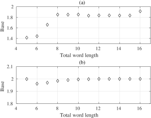
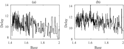
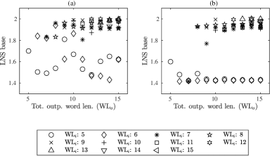
The problem of rounding a non-zero FP number to zero during conversion is the same as stated earlier in Section 3.2 and we exclude values that underflow or overflow during rounding, as also stated earlier in Section 3.2. Fig. 1(b) shows that for the distribution of FP numbers, the LNS base that gives the lowest quantization error is typically close to for all word lengths given in Table 1.
Note, however, that each LNS base gives both a different range of real-domain values, and a different distribution of those values, with bases close to base- having a range closest to a floating point distribution for a given word length. This is reflected in Fig. 1(b) where bases close to base- provide the least quantization error across all word lengths. We consider a second experiment where we apply a constant scaling factor to all LNS values, so that the range of LNS values is the same for all bases. With this scaling, different bases lead to different distributions of LNS values, but the range is constant. We use a scaling factor that is the ratio of the maximum floating point and LNS number for each base. Fig. 1(a) shows the effect of keeping the range of LNS values constant through scaling with different bases resulting in distributions that can reduce the quantization error, compared to base-. For very short word lengths of – , the optimal base for quantization error is much lower than base-.
The average absolute representation error, as a percentage of in the log domain and for a scaled LNS distribution, for a few select bases is shown in Table 2 along with the difference of other bases to the best base that gives the minimum representation error, in columns two and three. Other columns describe another type of error which will be explained shortly.
It can be seen from Table 2 that bases other than base- can give significant reduction in error, with a minimum improvement for over base- and a maximum of close to three order of magnitude for larger word lengths. However, the distribution and range of inputs may be domain dependent. A base that results in a distribution of values that is suitable for one domain might be a poor match for another domain. Thus, matching the LNS base to an input distribution may be useful when designing a hardware accelerator that targets a specific domain. But for general-purpose LNS processing, it is probably not worthwhile to build a base that is specific to one domain into the hardware LNS units. Our experiments show that we can adapt the LNS base to reduce the rounding when converting some input distribution to LNS. However, any reduction in conversion error may also be domain-dependent. In contrast, our approach in the next section improves the accuracy of arithmetic, and is less domain-dependent.
| Number format | Base | Avg. abs. repr. error (%) | Avg. abs. arith. error (%) | |||
| Q(2,2) | ||||||
| Q(2,3) | ||||||
| Q(3,3) | ||||||
| Q(4,3) | ||||||
| Q(4,4) | ||||||
| Q(4,5) | ||||||
| Q(4,6) | ||||||
| Q(4,7) | ||||||
| Q(4,8) | ||||||
| Q(4,9) | ||||||
| Q(4,10) | ||||||
| Q(5,10) | ||||||
-
Scaling factor,
-
Number of values rounded to zero in the real domain
5 LNS Addition and Subtraction
The set of LNS numbers is not closed under addition and subtraction. For example, if the exponent consists only of integer bits (i.e. ), then base- has real-domain numbers . The sum of two numbers in this set may not be a member of the set. For example, , but is not an element of the set. In practical LNSs, we round the results of addition and subtraction to the nearest representable LNS number. Thus, the and operations are not exact in LNS, leading to rounding error in these fundamental operations. These rounding errors are inherent in logarithmic number systems, regardless of how addition and subtraction are implemented.
However, different bases lead to the LNS containing different sets of values. For example, the set of LNS numbers with an integer exponent and base- contains numbers of the form
In this number system, if we add , the nearest representable LNS number is . Thus, both the set of representable values and the size of rounding errors depends on the base. A common way to compute LNS addition and subtraction uses the identities [6]:
| (8) |
where
| (9) |
where is the base, (op is for addition and for subtraction) and (where ). The functions and are non-linear, as shown in Fig. 2

The challenge of computing function can offset the gains achieved by other useful properties of LNS. A number of methods exist such look-up tables, CORDIC, Taylor series expansion or function approximation [8, 6]. We use the look-up table method, which requires space complexity, and is suitable for word lengths up to -bits [7]. For the low precision word sizes we consider, in the range bits, the look-up tables are relatively small.
We represent the and functions as look-up tables for different bases. LNS with fixed-point exponent is not closed under addition or subtraction, so we round the values in the tables to the nearest representable LNS number. Different LNS bases lead to number systems containing different sets of numbers. Thus, these look-up tables are different for each base, and therefore the rounding errors are different for each base.
Typically, in an LNS arithmetic unit, look-up tables are implemented as simple read-only memories (ROMs). However, in some cases, the table entries for the two functions are trivial with a very few non-zero values and thus realizing them as logic gates can be beneficial than implementing them as ROMs.
5.1 Realization of Large LNS/Small Linear Values in the Subtraction Tables
According to Equation 9, the first entry in the tables correspond to when and are equal. This entails two things. First, output of the subtraction of such numbers will be zero and that for , the first value corresponds to , which is . Similar to this, for the next few values, the difference between and is very small implying that subtraction between these two values results in a very small number. This also means that of Equation 8 returns a very large negative value.
These large negative values in the subtraction table correspond to very small values in the real domain, which are smaller than the smallest representable number. This number corresponds to . One needs to make a decision about their representation in the tables. In the real domain, values that are smaller than the smallest representable number are either rounded to zero or the smallest representable number, depending on the distance between the number itself and the two adjacent numbers. However, one cannot represent real zero in the LNS domain as that is equivalent to . Thus, the underlying question is the representation of linear zero/LNS in the subtraction tables.
Since in these cases the output of subtraction either results in a zero or a very small value that is to be rounded to zero in the real domain, we can utilize this by storing zeros in the table and having a small logic circuit that can detect such cases and forcing the output to zero. Storing zeros simplifies the logic circuitry synthesized for realizing the subtraction tables.
5.2 Evaluation of Arithmetic Error
We computed the arithmetic error as a percentage of in the log domain (where ) and considered bases ranged from and , similar to what was done for representation error. The rounding was computed in the log domain with the error measured as defined in Section 3.2.
The result is shown in Fig. 3(a,b) for various word lengths ranging from – bits (including one sign bit) where only the base that achieves the minimum arithmetic error for a given word length is shown. The error measures do not include errors generated when values are rounded to zero in the real domain and remain within the bounds given by Equation 6. Also shown in Fig. 3(c,d) is the variation in the average absolute arithmetic error as a percentage of (in the log domain) for and that for this particular case, base- and base- provide the lowest arithmetic error. This is also indicated in Table 2, where the results for arithmetic error were presented along with representation error. This is a and improvement for the addition and subtraction tables over standard base-.
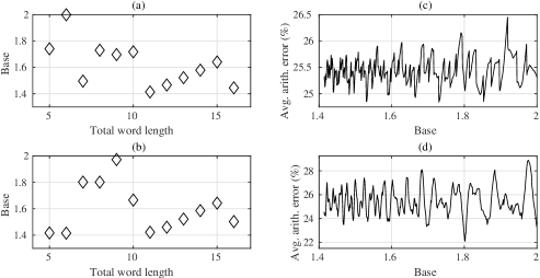
When rounding to nearest, the average arithmetic error will be around of the with the maximum absolute error being . Figure 3(a,b) shows that base- is not the best choice, especially for smaller word lengths.
As mentioned in Section 4, the errors generated due to representation an input distribution is highly domain dependent. However, the values in addition/subtraction tables are dependent on the particular arithmetic operation and the base in which they are represented and this result shows that rounding error for LNS arithmetic can be reduced by selection of an appropriate base.
However, different bases give minimum rounding error for the addition and subtraction tables for different word lengths. These bases do not correspond to the bases which give minimum representation error as shown in Fig. 1. In order to compare the arithmetic and representation error for different interesting bases, Table 2 shows them for each of these bases. It also identifies the best base for each type of error. Also shown are the number of values that are rounded to zero in the real domain. These values are not counted when computing the arithmetic error, for reasons explained in Section 3.2.
Typically, for the fixed point exponent, rounding to nearest results in a maximum error of one half of the and average error of one quarter of the . However, it can be seen in Table 2 that for very short word lengths, the average arithmetic error for bases other than base- is much lower than , specially for the subtraction table. For e.g., base- gives an arithmetic error of of for while base gives of (in the log domain) for . These errors converge to around as we increase the word length.
Furthermore, as compared to base-, significant improvements can be achieved as compared to base- of up to and for addition and subtraction tables, respectively for . It can also be seen that the representation error for bases which give minimum arithmetic error is typically within the range expected of average rounding error, bar only one exception when the word length specification matches that of half-precision floating point ().
6 Synthesis of Addition and Subtraction Tables
A number of methods exist in literature for realizing Equation 8 in hardware, as mentioned in Section 5. However, since we are dealing with short word lengths, table based approach is the preferred choice [7].
The functions of are evaluated by storing pre-computed values in a look-up table and then reading the appropriate value based on the input. The values in the table are quantized to the given word length, various choices for which are listed in Table 1. Typically, look-up tables are realized using read-only ROMs. However, if the table entries are fairly simple, they can be realized using logic gates rather than ROMs. One can also realize some columns of the table using logic gates and others using a ROM depending on the complexity of the columns.
Thus, to realize tables, one has three options:
-
•
Synthesize the whole table as a ROM
-
•
Synthesize the whole table using logic gates
-
•
Synthesize parts of the table using logic gates and parts using a ROM
A simple, fixed ROM usually consume only one transistor per bit for data storage [32]. However, even a simple fixed ROM will have additional circuitry as a row/column decoder, sense amplifiers and precharge transistors [33]. A simple differential sense amplifier will consist of five transistors [34] while one needs one precharge transistor per one column of bits. The address decoding for a memory is typically performed by a combination of row and column decoders if memories are arranged as a matrix of words rather than a one dimensional array of individual words or only one address decoder if arranged as a one dimensional array structure.
In the case of realizing the tables using logic gates, one can either synthesize the logic for individual column of bits independently or combine the columns to enable the synthesis tool to share logic to realize various columns of bits. In our experiments, the total synthesis cost, which we present in terms of transistors, for a combined synthesis of columns of bits is lower than synthesizing individual columns separately. We use the open source ABC synthesis tool [35] and provide the tool with tables described using the Berkeley logic interchange format (BLIF) file [36] and a library containing only NAND, NOR and Inverter gates to enable us to estimate the number of transistors. Each NAND and NOR gate is typically made up of four transistors while the inverter is made up of two transistors [34]. This can be described as a first degree estimation as we do not take into account the differences in the sizes of the two different types of transistors, the NMOS (N-type Metal Oxide Semiconductor transistor) and PMOS (P-type metal oxide semiconductor transistor) which are used to realize the gates using the complementary MOS technology [34].
However, the question about when to use logic gates and when to use ROM will depend on a threshold. The threshold will be the point when the cost of implementing using gates goes beyond that of ROM which has a constant cost of implementation.
Consider the example of -bit LNS which requires only with the sign bit not stored. If realized as an array structure, the cost for such a ROM will be transistors for the storage, transistors for the precharge, transistors for sense amplifiers and transistors for a decoder. The implementation cost for the decoder was estimated by synthesizing the decoder using the ABC synthesis tool which was provided a BLIF file describing the truth table of it. This makes for a total cost of transistors.
However, if we implement the memory as a matrix of words, one will need a row and column decoder which cost and transistors respectively, making the total cost of the memory to be: transistors. This number can be further reduced by investigating the values each of the addition and subtraction table takes. For the subtraction table, one needs all bits of output, however, for the addition table, one can discard the two most significant bits (as they are zero) and only store the least significant five bits. This is also evident by Fig. 2 where the range of is limited between zero and one while that of is much larger. This can reduce the total cost for the addition table to transistors. All of this is summarized in Table 3.
| Type of ROM | Storage | Precharge | Sense amplifier | Decoder | Total |
|---|---|---|---|---|---|
| ROM with one decoder | |||||
| ROM with two decoders | |||||
| -bit ROM with two decoders |
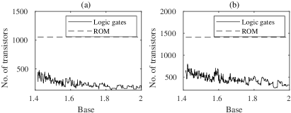
Comparing the cost of ROM with logic gates for realizing complete table shows that for all bases, tables realized using gates has lower area as compared to ROM, as shown in Fig. 4 for -bit LNS for all combination of bases between and , with a minimum savings of and for the addition and subtraction tables, respectively.
6.1 Tables using Gates and ROM
Another approach to realize these tables is to realize some columns using logic gates and some using ROM. This may appear beneficial because for those columns with only a few , a gate based realization will result in very small circuits while for the columns where changes in the value are too frequent, a ROM based implementation may be better or of similar complexity as compared to a gate based implementation.
However, experimental evaluation shows that is not the case, as shown in Fig. 5 for select bases which give the minimum and maximum transistor count for each table. The x-axis in each sub-figure shows the number of memory columns where rev. means that columns are combined starting from least significant column while the other alternative shows the starting point is the most significant columns. For the addition table, the two most significant columns are not shown as they are all zeros.
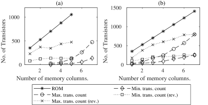
Figure 5 shows that the maximum transistor count for the addition table increases from transistors for a single column to transistors for all columns combined using logic gates for base-. This is an improvement of to . Similarly, the savings in transistor count for the subtraction case, in the worst case, is to . Even when combining the columns starting from the most significant column results in lower transistor count as compared to realizing the tables using a ROM.
Thus, considering only the perspective of transistor count, realizing the tables using only logic gates results in a lower transistor count as compared to a simple ROM. Fig. 5 also indicates that for -bit LNS, a base of and gives minimum transistor count for addition and subtraction table, respectively. Thus with a selection of base other than base-, one can also reduce the implementation cost.
6.2 Delay of Logic Circuit for Tables
Typically, for a given word length, the latency of reading a word from a ROM will be the same across all reads, specially if the word being read are in different rows. In a typical implementation, the row address is asserted first to read the whole row (consisting of multiple words) into the sense amplifiers from where the exact word is selected using the column address. The latency of the two decoders ( and , as given in Section 6) each for - and -bit memories is and time units respectively. Only considering the sum of the delay of the two decoders and ignoring the delay associated with the actual reading of the value from transistors, sense amplifiers and any refresh times required, the total delay is time units.
However, the delays associated with realizing the tables as logic gates for different bases and -bit output is shown in Fig. 6. The difference between the delay associated with logic gates and ROM based implementation is not significant. With a very significant difference between the transistors required to realize the two alternatives for realizing the addition and subtraction tables, as shown in Figs. 4 and 5, it can be concluded that it is better to use logic gates for realizing the tables for -bit LNS.
7 Deciding the Trade-off for Addition and Subtraction Tables
Four parameters have been discussed in the previous sections. They are:
-
•
Representation error
-
•
Arithmetic error for and
-
•
Area in terms of transistors count for realizing tables using gates for and
-
•
Delay for realizing tables using gates for and
For each parameter, there are unique bases in the LNS that gives the corresponding minimum value. The most important of the these parameters are the two types of errors.
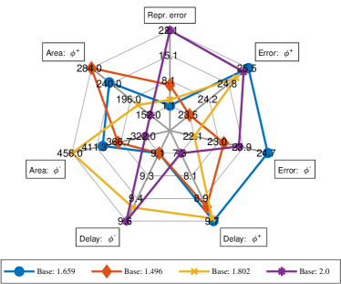
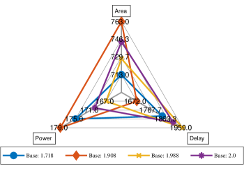
The trade-offs involved for one particular word length of is shown in Fig. 7 for various bases. Similar trade-offs exist for other word lengths. All parameters have their importance in the overall design and implementation and each base is optimal in one of the four parameters defined above but none of the base is optimal in all of the four parameters. This figure emphasize our point of the need of analyzing different bases and the priorities while designing and implementing any system. However, it has been clearly shown that base- is not optimal under different word lengths and for different parameters.
8 Higher Precision Tables for Very Short Word Lengths
As mentioned earlier, a number of works use very short word lengths for realizing different systems for deployment on edge devices. However, short word lengths can introduce significant precision errors for addition and subtraction. One way to circumvent this is to use tables with higher precision for table values (referred from here on as mixed precision tables for exploratory convenience) and rounding the result only after all required operations for, say, computing the sum of products of data and coefficients in an FIR filter is complete. Thus, there is only one source of arithmetic error at the output (at the cost of higher hardware cost).
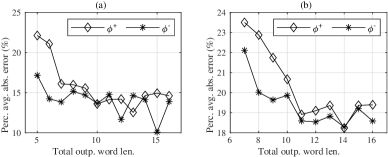
The number format given in Table 1 was used for the analysis with fractional word length successively increased up to a maximum of total word length of (including the sign bit) for each case. For e.g., for the case of , the input word length is -bits while the output word length is varied from – bits. The results for two different total input word length, Q(2,2) and Q(3,3), are shown in Fig. 8, where each value represents the minimum percentage average absolute arithmetic error. For each value, the base that gives this minimum value is unique. As discussed earlier in Section 5.2, for shorter word lengths, the arithmetic error can be reduced much lower than of for bases other than base-.
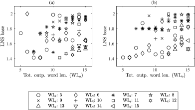
For each number format given in Table 1 and all output word lengths, there is no single optimal base which gives the least arithmetic error for various combinations of integer and fractional bits. This phenomenon is further emphasized in Fig. 9 which identifies the various bases which give the least arithmetic error for total output word length. The legend shows the original total word length (without extended fractional bits). For e.g., the plot shows the optimal base for output word lengths ranging from – bits for the case of . Again it re-emphasizes the earlier reached conclusion that bases other than base- should be considered when designing a system as it can give lower error and implementation cost.
8.1 Synthesis of Higher Precision Tables for Very Short Word Lengths
The other key issue to deal with extra fractional bits is the size of these tables, once they are realized in hardware. As shown in Figs. 4 and 5, it is better to realize the tables using gates. However, with increasing output word length for the tables, one needs to analyze whether the conclusion reached in Section 6 still stands. For this, the addition and subtraction tables were synthesized using both ROM and standard cell gates for all input and output word length combinations. Table 4 shows the number of transistors required to realize the ROMs based on the model earlier defined in Section 6. The size of decoders for the various tables were chosen so as to achieve minimum transistor count for their implementation.
| Input word length () | Transistor count for ROM (with various output word lengths ()) | |||||||||||
|---|---|---|---|---|---|---|---|---|---|---|---|---|
| 168 | 196 | 224 | 252 | 280 | 308 | 336 | 364 | 392 | 420 | 448 | 476 | |
| – | 345 | 401 | 457 | 513 | 569 | 625 | 681 | 737 | 793 | 849 | 905 | |
| – | – | 661 | 749 | 837 | 925 | 1013 | 1101 | 1189 | 1277 | 1365 | 1453 | |
| – | – | – | 1408 | 1584 | 1760 | 1936 | 2112 | 2288 | 2464 | 2640 | 2816 | |
| – | – | – | – | 2736 | 3040 | 3344 | 3648 | 3952 | 4256 | 4560 | 4864 | |
| – | – | – | – | – | 5844 | 6452 | 7060 | 7668 | 8276 | 8884 | 9492 | |
| – | – | – | – | – | – | 11832 | 12952 | 14072 | 15192 | 16312 | 17432 | |
| – | – | – | – | – | – | – | 25400 | 27640 | 29880 | 32120 | 34360 | |
| – | – | – | – | – | – | – | – | 52728 | 57016 | 61304 | 65592 | |
| – | – | – | – | – | – | – | – | – | 113020 | 121596 | 130172 | |
| – | – | – | – | – | – | – | – | – | – | 237312 | 254080 | |
| – | – | – | – | – | – | – | – | – | – | – | 506112 | |
The addition () and subtraction () tables were also synthesized for all input and output word length combinations using standard cell logic gates. For each case, the base which gives the minimum transistor count is unique and a distribution of these bases is shown in Fig. 10. This figure, together with the results shown in Fig. 9, identifies the various bases which give minimum arithmetic error and implementation cost, respectively, with lower the word length, the more smaller bases give minimum transistor count.
However, arithmetic error is more important than transistor count to ensure correctness of result. Although the hardware cost of realizing tables with bases giving minimum arithmetic error is larger than the best case in terms of transistor count, it is still significantly better than realizing it in ROMs. Results for the subtraction table are shown in Table 5 as typically it is more complex to realize than the addition table and shows an order of magnitude improvement, with a minimum reduction of in transistor count to a maximum of nearly reduction.
| Input word length () | Transistor Count for ROM (with various output word lengths ()) | |||||||||||
|---|---|---|---|---|---|---|---|---|---|---|---|---|
| 64 | 96 | 122 | 120 | 156 | 186 | 208 | 214 | 244 | 254 | 282 | 290 | |
| – | 158 | 244 | 264 | 394 | 416 | 486 | 452 | 530 | 614 | 662 | 788 | |
| – | – | 456 | 454 | 686 | 808 | 834 | 810 | 1114 | 1026 | 1336 | 1484 | |
| – | – | – | 494 | 530 | 608 | 872 | 1218 | 1074 | 1768 | 1428 | 2582 | |
| – | – | – | – | 878 | 1326 | 1744 | 2996 | 2122 | 3962 | 3018 | 4460 | |
| – | – | – | – | – | 1746 | 3604 | 4196 | 5150 | 6040 | 4310 | 7528 | |
| – | – | – | – | – | – | 6132 | 7130 | 8916 | 10080 | 10664 | 12458 | |
| – | – | – | – | – | – | – | 10448 | 13072 | 15884 | 16184 | 19132 | |
| – | – | – | – | – | – | – | – | 18962 | 21918 | 27644 | 31194 | |
| – | – | – | – | – | – | – | – | – | 33438 | 41068 | 50580 | |
| – | – | – | – | – | – | – | – | – | – | 63140 | 75726 | |
| – | – | – | – | – | – | – | – | – | – | – | 66608 | |
It can also be seen from Table 5 that as the output word length increases, for each input word length, the transistor count does not increase significantly, making the mixed precision approach an attractive one given the reduced error measurement.
9 LNS Adder and Multiplier Design in Fixed and Floating Point Number System
As identified in Sections 1 and 2, logarithmic number system (LNS) finds application in signal processing and neural networks. Both of these systems are based heavily on the operation of addition and multiplication. The key advantage of LNS over fixed and floating point stem from its inherent simplification of multiplication into addition. However, the drawback with LNS is that it can only approximate the addition operation since addition is not closed under LNS, as outlined in Section 5.
Since multiplication in LNS is reduced to addition, the circuit to realize an LNS multiplier will be similar in complexity to that of a fixed point adder [37]. This is because the exponent of the LNS is typically represented using fixed point. In order to ascertain which number system to use from a hardware complexity purpose it is important to realize the hardware circuit for LNS addition/subtraction and compare it against fixed point multiplier. Since in applications like neural networks the dominant number system used is floating point, it is important to realize floating point addition and multiplication circuits to analyze which number system provides the smallest circuit.
The circuit to perform addition and subtraction in LNS is given in Fig. 11 and is a modified form of the circuit given by Kenny et al in [6]. In the circuit, the functions of and are implemented using look-up tables, as mentioned in Section 6. The zero detect module shown takes into account whether the two numbers being added are both zero (shown by the bit of Equation(1)), the difference of two number is zero or so small that the result will be rounded to zero in the real/linear domain, as discussed in Section 5.1.

Addition and multiplier circuits were synthesized for logarithmic, fixed and floating point number systems for word length ranging from five to -bits using Cadence Genus with the 45nm GSCL liberty cell library from the Free45PDK. For LNS, the bases were varied from to , similar to how LNS is analyzed in the previous sections. The results are shown in Table 6 where indicates integer and fractional bits and does not include the sign bit. For fixed point, it needs to be read as since complement number representation is assumed and for floating point, results for both adder (Float.A) and multiplier (Float.M) are presented.
As evident in Table 6 the LNS adder requires lower or similar area as compared to fixed point multipliers for short word lengths up to . Although the floating point multiplier is the smaller of all circuits (for most of the cases), the LNS multiplier and fixed-point adder will be more simpler and smaller than it, thus overall, floating point will not have the smallest of the circuit. Also important to realize is that for LNS, the same circuit is used to perform both addition and subtraction which opens up the possibility of re-using the same circuit for the two operations if the input sample rate allows for some level of multiplexing. Furthermore, for LNS, the adder and subtractor were realized using the look-up table approach for implementing the functions and in Equation (8). They can also be realized using different techniques like weighted sum of bit-products [6] which can reduce the area complexity. However, in this work all error calculations are based on table based implementations, the same method was used for realizing circuits for consistency.
| Number format | Circuit type | Area () | Delay () | Power () | Number format | Circuit type | Area () | Delay () | Power () |
|---|---|---|---|---|---|---|---|---|---|
| Fixed | 495 | 874 | 101 | Fixed | 688 | 1035 | 146 | ||
| Float.M | 415 | 991 | 80 | Float.M | 576 | 1467 | 101 | ||
| Float.A | 565 | 1868 | 108 | Float.A | 706 | 2325 | 120 | ||
| LNS () | 445 | 1316 | 109 | LNS () | 577 | 1650 | 148 | ||
| LNS () | 423 | 1214 | 107 | LNS () | 564 | 1583 | 147 | ||
| Fixed | 890 | 1190 | 195 | Fixed | 1143 | 1328 | 251 | ||
| Float.M | 680 | 1504 | 126 | Float.M | 730 | 1620 | 135 | ||
| Float.A | 913 | 2922 | 170 | Float.A | 1002 | 3314 | 170 | ||
| LNS () | 744 | 1900 | 170 | LNS () | 883 | 2170 | 197 | ||
| LNS () | 713 | 1832 | 175 | LNS () | 857 | 2061 | 191 | ||
| Fixed | 1332 | 1515 | 303 | Fixed | 1599 | 1753 | 379 | ||
| Float.M | 962 | 1931 | 180 | Float.M | 1102 | 2307 | 216 | ||
| Float.A | 1145 | 3179 | 222 | Float.A | 1305 | 3557 | 249 | ||
| LNS () | 1325 | 2477 | 263 | LNS () | 1622 | 2477 | 263 | ||
| LNS () | 1244 | 2660 | 264 | LNS () | 1572 | 2930 | 347 | ||
| Fixed | 1856 | 1890 | 458 | Fixed | 2208 | 2109 | 541 | ||
| Float.M | 1328 | 2518 | 258 | Float.M | 1553 | 2831 | 318 | ||
| Float.A | 1460 | 4118 | 288 | Float.A | 1653 | 4688 | 350 | ||
| LNS () | 2643 | 3374 | 552 | LNS () | 4319 | 4342 | 824 | ||
| LNS () | 2523 | 3316 | 550 | LNS () | 4113 | 4022 | 804 | ||
| Fixed | 2531 | 2502 | 646 | Fixed | 2842 | 2652 | 726 | ||
| Float.M | 1796 | 3008 | 380 | Float.M | 2062 | 3364 | 438 | ||
| Float.A | 1769 | 4528 | 355 | Float.A | 1958 | 5358 | 423 | ||
| LNS () | 7468 | 5419 | 1269 | LNS () | 13155 | 6328 | 1897 | ||
| LNS () | 7289 | 5176 | 1234 | LNS () | 13032 | 6341 | 1906 |
For each number format, the result for LNS other than base- is the base which gives the lowest area. This does not correspond to the shortest delay through the circuit or the lowest power consumption. Fig. 12 gives a better insight into the inherent trade-offs involved here.
10 Finite-Impulse Response (FIR) Filter: An Application
Frequency selective finite-length impulse response (FIR) filters are used in many applications and are therefore a key building block in a digital signal processing system[38]. The difference equation that defines the output of an th-order (length ) FIR filter is:
| (10) |
where is the output sequence, is the input sequence, and are the coefficients. The direct form of FIR filter to realize Equation(10) is shown in Fig. 13.

The arithmetic complexity of FIR filters primarily depends on the number of multiplications, which according to (10) is proportional to the filter order. The filter order is, for linear-phase single stage FIR (SSF) filters, roughly proportional to the inverse of the width of the transition band [38].
With LNS reducing multiplication to an addition, it finds application in applications like FIR filters where the main operator contributing towards overall hardware complexity is multiplication. However, as stated earlier, addition/subtraction in LNS is non-trivial and requires a table based implementation as shown in Fig. 11. As shown in Section 9, LNS provides lower hardware cost in terms of area for short word length adders/subtractors as compared to its counterparts, it is important to analyze whether these benefits extend to FIR filters.
For this analysis, a order FIR filter was implemented in hardware using the same setup as described in Section 9 with fixed, floating and logarithmic number systems. The input, output and filter coefficients were assumed to be in respective number systems. For LNS, the FIR filter was realized for a select number of bases identified earlier in Tables 2 and 6. The results of this analysis is shown in Table 7.
The results shown in Table 7 are consistent with those shown in Table 6. FIR filters realized using logarithmic number systems achieve a lower area (minimum savings of ) while also having the shortest delay (minimum improvement of )and lower power consumption (minimum improvement of )as compared to its fixed and floating point counterparts up to the word length corresponding to . Overall, LNS based FIR filters also are the fastest even though occupies an area that is, at a maximum, nearly more than others.
| Number format | Circuit type | Area () | Delay () | Power () | Number format | Circuit type | Area () | Delay () | Power () |
|---|---|---|---|---|---|---|---|---|---|
| Fixed | 4914 | 193 | 1700 | Fixed | 6841 | 197 | 2424 | ||
| Float | 7891 | 414 | 3346 | Float | 10877 | 411 | 5200 | ||
| LNS () | 3663 | 185 | 1542 | LNS () | 5301 | 189 | 2443 | ||
| LNS () | 3454 | 185 | 1297 | LNS () | 4620 | 185 | 1828 | ||
| Fixed | 8964 | 202 | 3239 | Fixed | 11456 | 208 | 4251 | ||
| Float | 12554 | 458 | 5694 | Float | 13693 | 524 | 5275 | ||
| LNS () | 6691 | 194 | 3007 | LNS () | 8393 | 195 | 3231 | ||
| LNS () | 6568 | 194 | 2957 | LNS () | 8044 | 195 | 3117 | ||
| Fixed | 14104 | 207 | 5269 | Fixed | 16857 | 216 | 6601 | ||
| Float | 16418 | 540 | 6042 | Float | 19250 | 560 | 7907 | ||
| LNS () | 11945 | 190 | 4810 | LNS () | 16954 | 195 | 7406 | ||
| LNS () | 12436 | 194 | 4969 | LNS () | 16554 | 195 | 7223 | ||
| Fixed | 20860 | 246 | 8091 | Fixed | 23762 | 244 | 9373 | ||
| Float | 23351 | 587 | 9999 | Float | 27019 | 619 | 11221 | ||
| LNS () | 27674 | 190 | 12295 | LNS () | 45148 | 195 | 18193 | ||
| LNS () | 27183 | 190 | 12019 | LNS () | 44707 | 190 | 11896 | ||
| Fixed | 27866 | 256 | 11087 | Fixed | 31347 | 251 | 12698 | ||
| Float | 30055 | 674 | 13238 | Float | 37063 | 659 | 15873 | ||
| LNS () | 81810 | 189 | 32375 | LNS () | 146520 | 189 | 47353 | ||
| LNS () | 79898 | 195 | 31760 | LNS () | 149660 | 185 | 48731 |
The large area for LNS based FIR filters for larger word lengths is due to the exponential increase in the memory size required for implementing the and functions, as given in Equation 8. This can be reduced by using approaches like the co-transformation approach by Arnold et al. in [39], the multi-table approach proposed by Coleman et al. in [7] or the multipartite table methods proposed by Dinechin et al. in [40].
| Base | ||||||||||
|---|---|---|---|---|---|---|---|---|---|---|
| Fixed LNS | ||||||||||
| LNS Fixed | ||||||||||
| Base | ||||||||||
| Fixed LNS | ||||||||||
| LNS Fixed | ||||||||||
Typically conversion can be carried out offline and all calculations can be done online in LNS. However, to show the cost of conversion between logarithmic and fixed point, conversion circuits were realized as look-up tables and synthesized using the same process as FIR filter. Only conversion between LNS and fixed point is shown since FIR filters are typically implemented using fixed point. The results are shown in Table 8 and it can be seen that the cost of realizing FIR filters using LNS is still lower than using fixed point, albeit with reduced margins, including conversion results, up to word length of . Optimized circuits for conversion have been proposed in the literature by Nam et al. in [41], Zhu et al. in [42] and others which can help in reducing this cost.
11 Conclusion
Logarithmic number system (LNSs) are a valuable alternative to floating point for embedded systems and domain-specific hardware accelerators. Existing LNS research has almost exclusively used base-. Although other bases, such as base- or base- have been explored, we show that these are simple aliases of base-, which can be constructed by moving the binary point of the fixed-point exponent in a base- LNS.
In this paper we show that non-base- LNSs can have significant advantages, particularly for short word lengths from bits. We first define a numeric error for LNS that measure as an absolute error in the fixed-point exponent of the LNS, which corresponds to a multiplicative error in the corresponding real domain value. We show that errors in conversion to LNS can be reduced dramatically by choosing an appropriate base and scaling factor, at least for the distribution of FP numbers. In our experiments, we reduce the typical conversion error from to less than .
We note that LNSs with a fixed word size are not closed under addition or subtraction, which leads to rounding errors in these operations. We also show that for a given LNS word size, some LNS bases lead to inherently lower average rounding errors. When rounding to nearest, the maximum arithmetic error for non-special values is 0.5 , and we expect the average to be around 0.25 . For example, in 5-bit (i.e. Q(2,2)) LNS, we show that base- leads to average errors of 0.260 (add) and 0.254 (subtract) . In contrast, base- gives an average error of just 0.227(add) and 0.172 (subtract) . Over millions of operations, even small differences in rounding errors can accumulate to large errors.
Although LNS add/subtract are often implemented with low-latency ROM lookup tables, we show that for small word sizes implementing these functions in dedicated logic is also efficient. The choice of base affects the truth table of the functions computed for LNS add/subtract, and can therefore affect the area and latency of the add/subtract units. By appropriate choice of base, the logic area of the and logic can be reduced by around 2.
We also analyzed mixed precision tables, where the values stored in the tables were of higher precision than the input. This can reduce the errors for low precision arithmetic. The building blocks of adder, subtractor and multiplier are implemented using logarithmic, fixed and floating point numbers and extended to a complete FIR filters and we showed that LNS can be beneficial from all aspects of area, delay and power for very short word lengths.
We conclude that the choice of base affects the conversion errors, arithmetic errors, and hardware implementation of arithmetic units on several dimensions and that LNS can be used to implement different systems, like the FIR filter. Different bases allow different trade-offs between these goals. Although prior research in LNS has generally assumed base-, our results show that other bases can reduce arithmetic and conversion errors while simultaneously reducing the area and latency of add/subtract and FIR units. Thus, when designing a low-precision LNS for custom hardware, one should consider looking beyond base-.
Acknowledgments
This material is based upon work supported, in part, by Science Foundation Ireland under Grant No. 13/RC/2094_P2 and, in part, by the European Union’s Horizon 2020 research and innovation programme under the Marie Skłodowska-Curie grant agreement and Grant No. 754489. Any opinions, findings, and conclusions or recommendations expressed in this material are those of the author and do not necessarily reflect the views of the Science Foundation Ireland and European Union’s Horizon 2020 programme.
We also extend our gratitude to Dr. Oscar Gustafsson of Linköping University, Sweden and Institute of Technology Carlow, Carlow, Ireland for their support.
References
- [1] M. Satyanarayanan. The emergence of edge computing. Computer, 50(1):30–39, January 2017.
- [2] W. Shi, J. Cao, Q. Zhang, Y. Li, and L. Xu. Edge computing: Vision and challenges. 3:637–646, 2016.
- [3] J. Chen and X. Ran. Deep learning with edge computing: A review. 107:1655–1674, 2019.
- [4] S. A. Alam and O. Gustafsson. Design of finite word length linear-phase FIR filters in the logarithmic number system domain. VLSI Des., 2014:14, 2014.
- [5] I. Kouretas, Ch. Basetas, and V. Paliouras. Low-power logarithmic number system addition/subtraction and their impact on digital filters. IEEE Trans. Comput., 62(11):2196–2209, 2013.
- [6] K. Johansson, O. Gustafsson, and L. Wanhammar. Implementation of elementary functions for logarithmic number systems. IET Comput. Digit. Tech., 2(4):295–304, June 2008.
- [7] J. N. Coleman et al. The european logarithmic microprocesor. IEEE Trans. Comput., 57(4):532–546, April 2008.
- [8] A.M. Mansour, A.M. El-Sawy, M.S. Aziz, and A. T. Sayed. A new hardware implementation of base 2 logarithm for FPGA. Int. J. Signal Proc. Syst., 3(2):171–181, 2015.
- [9] Z. G. Feng and K. F. C. Yiu. A new formulation for the design of FIR filters with reduced hardware implementation complexity. In Proc. IEEE Int. Conf. Green Circuits Syst., pages 242–246, Shanghai, China, June 2010.
- [10] M. Rastegari, V. Ordonez, J. Redmon, and A. Farhadi. Xnor-net: Imagenet classification using binary convolutional neural networks, March 2016.
- [11] A. Capotondi, M. Rusci, M. Fariselli, and L. Benini. Cmix-nn: Mixed low-precision cnn library for memory-constrained edge devices. 67(5):871–875, 2020.
- [12] A. Garofalo, M. Rusci, F. Conti, D. Rossi, and L. Benini. Pulp-nn: accelerating quantized neural networks on parallel ultra-low-power risc-v processors. 378, December 2019.
- [13] N. Bruschi, A. Garofalo, F. Conti, G. Tagliavini, and D. Rossi. Enabling mixed-precision quantized neural networks in extreme-edge devices. In Proc. ACM Int. Conf. on Computing Frontiers, pages 217–220, 2020.
- [14] E. Chung and J. Fowers et al. Serving DNNs in real time at datacenter scale with project brainwave. IEEE Micro, 38(2):8–20, March 2018.
- [15] V.B. Lawrence and A.C. Salazar. Finite precision design of linear-phase FIR filters. Bell Syst. Tech. J., 59(9):1575–1598, November 1980.
- [16] I. Hubara, M. Courbariaux, D. Soudry, R. El-Yaniv, and Y. Bengio. Quantized neural networks: Training neural networks with low precision weights and activations. ACM J. Mach. Learn. Res., 18(1):6869–6898, January 2017.
- [17] N. Wang, J. Choi, D. Brand, C.-Y. Chen, and K. Gopalakrishnan. Training deep neural networks with 8-bit floating point numbers. In Proc. Advances in Neural Information Processing Syst., pages 7675–7684, 2018.
- [18] Y. Wang, J. Lin, and Z. Wang. An energy-efficient architecture for binary weight convolutional neural networks. IEEE Trans. VLSI Syst., 26(2):280–293, February 2018.
- [19] E. H. Lee, D. Miyashita, E. Chai, B. Murmann, and S. S. Wong. Lognet: Energy-efficient neural networks using logarithmic computation. In Proc. IEEE Int. Conf. Acoust. Speech Signal Process., pages 5900–5904, March 2017.
- [20] D. Miyashita, E. H. Lee, and B. Murmann. Convolutional neural networks using logarithmic data representation, 2016.
- [21] N. G. Kingsbury and P. J. W. Rayner. Digital filtering using logarithmic arithmetic. Electron. Lett., 7(2):56–58, January 1971.
- [22] M. G. Arnold. Reduced power consumption for MPEG decoding with LNS. In Proc. IEEE Int. Applicat.-Specific Syst. Arch. Processors Conf., pages 65–67, 2002.
- [23] V. Paliouras and T. Stouraitis. Logarithmic number system for low-power arithmetic. In Proc. Int. Workshop Power Timing Modeling Optimization Simulation, volume 1918, pages 285–294, 2000.
- [24] C. Basetas, I. Kouretas, and V. Paliouras. Low-power digital filtering based on the logarithmic number system. In Proc. Int. Workshop Power Timing Modeling Optimization Simulation, volume 4644, pages 546–555. 2007.
- [25] D. V. Satish Chandra. Error analysis of FIR filters implemented using logarithmic arithmetic. IEEE Trans. Circuits Syst. II, 45(6):744–747, June 1998.
- [26] Sebastian Vogel, Mengyu Liang, Andre Guntoro, Walter Stechele, and Gerd Ascheid. Efficient hardware acceleration of CNNs using logarithmic data representation with arbitrary log-base. In Proc. IEEE/ACM Conf. Comput.-Aided Design., ICCAD ’18, pages 9:1–9:8, New York, NY, USA, 2018. ACM.
- [27] M. Arnold, E. Chester, and C. Johnson. Training neural nets using only an approximate tableless LNS ALU. In Proc. IEEE Int. Applicat.-Specific Syst. Arch. Processors Conf., pages 69–72, 2020.
- [28] J. N. Mitchell. Computer multiplication and division using binary logarithms. IRE Trans. Electron. Comp., EC-11(4):512–517, 1962.
- [29] E.E. Swartzlander Jr. and A.G. Alexopoulos. The sign/logarithm number system. IEEE Trans. Comput., C-24(12):1238–1242, December 1975.
- [30] T. Stouraitis and V. Paliouras. Considering the alternatives in low-power design. IEEE Circuits Syst. Mag., 17(4):22–29, August 2002.
- [31] D. V. S. Chandra. Error analysis of FIR filters implemented using logarithmic arithmetic. 45(6):744–747, 1998.
- [32] Wai-Kai Chen, editor. Memory, microprocessor and ASIC. CRC Press, 2003.
- [33] B-.D. Yang and L.-S. Kim. A low-power charge-recycling rom architecture. 4(4):590–600, 2003.
- [34] A. S. Sedra, K. C. Smith, T. C. Carusone, and V. Gaudet. Microelectronic Circuits. Oxford University Press, 8 edition, November 2019.
- [35] Alan Mishchenko. Abc: A system for sequential synthesis and verification, 2005.
- [36] Berkeley logic interchange format (blif). University of California, Berkeley, 1992.
- [37] I. Kouretas and V. Paliouras. Logarithmic number system for deep learning. In Proc. Int. Conf. Modern Circuits and Syst. Technologies., pages 1–4, 2018.
- [38] Sanjit K. Mitra. Digital Signal Processing. TATA McGraw-Hill, University of California, Santa Barbara, 2006.
- [39] M. G. Arnold, T. A. Bailey, J. R. Cowles, and M. D. Winkel. Arithmetic co-transformations in the real and complex logarithmic number systems. IEEE Trans. Comput., 47(7):777–786, 1998.
- [40] F. de Dinechin and A. Tisserand. Some improvements on multipartite table methods. In Proc. IEEE Symp. Comput. Arithmetic, pages 128–135, 2001.
- [41] B. Nam, H. Kim, and H. Yoo. Power and area-efficient unified computation of vector and elementary functions for handheld 3d graphics systems. IEEE Trans. Comput., 57(4):490–504, 2008.
- [42] M. Zhu, Y. Ha, C. Gu, and L. Gao. An optimized logarithmic converter with equal distribution of relative errors. IEEE Transactions on Circuits and Systems II: Express Briefs, 63(9):848–852, 2016.