- CDG
- Coverage Directed Test Generation
- AST
- Abstract Syntax Tree
- CRV
- Constrained Random Verification
- CVE
- Common Vulnerability Exposure
- DV
- Design Verification
- DUT
- Design Under Test
- E2E
- End-to-End
- FSM
- Finite State Machine
- GCP
- Google Cloud Platform
- GCS
- Google Cloud Storage
- HDL
- Hardware Description Language
- HSB
- Hardware Simulation Binary
- HWFP
- Hardware Fuzzing Pipeline
- IP
- Intellectual Property
- LOC
- Lines of Code
- RTL
- Register Transfer Level
- RoT
- Root-of-Trust
- SoC
- System-on-Chip
- SUT
- System Under Test
- SVA
- SystemVerilog Assertion
- TL-UL
- TileLink Uncached Lightweight
- UVM
- Universal Verification Methodology
Fuzzing Hardware Like Software ††thanks: The project depicted is sponsored in part by the Defense Advanced Research Projects Agency, and the National Science Foundation under Grant CNS-1646130. The content of the information does not necessarily reflect the position or the policy of the Government, and no official endorsement should be inferred. Approved for public release; distribution is unlimited.
Abstract
Hardware flaws are permanent and potent: hardware cannot be patched once fabricated, and any flaws may undermine even formally verified software executing on top. Consequently, verification time dominates implementation time. The gold standard in hardware Design Verification (DV) is concentrated at two extremes: random dynamic verification and formal verification. Both techniques struggle to root out the subtle flaws in complex hardware that often manifest as security vulnerabilities. The root problem with random verification is its undirected nature, making it inefficient, while formal verification is constrained by the state-space explosion problem, making it infeasible to apply to complex designs. What is needed is a solution that is directed, yet under-constrained.
Instead of making incremental improvements to existing hardware verification approaches, we leverage the observation that existing software fuzzers already provide such a solution; we adapt it for hardware verification, thus leveraging existing—more advanced—software verification tools. Specifically, we translate RTL hardware to a software model and fuzz that model. The central challenge we address is how best to mitigate the differences between the hardware execution model and software execution model. This includes: 1) how to represent test cases, 2) what is the hardware equivalent of a crash, 3) what is an appropriate coverage metric, and 4) how to create a general-purpose fuzzing harness for hardware.
To evaluate our approach, we design, implement, and open-source a Hardware Fuzzing Pipeline that enables fuzzing hardware at scale, using only open-source tools. Using our pipeline, we fuzz four IP blocks from Google’s OpenTitan Root-of-Trust chip. Our experiments reveal a two orders-of-magnitude reduction in run time to achieve Finite State Machine (FSM) coverage over traditional dynamic verification schemes. Moreover, with our design-agnostic harness, we achieve over 88% HDL line coverage in three out of four of our designs—even without any initial seeds.
Index Terms:
Hardware Security, Design Verification, FuzzingI Introduction
As Moore’s Law [1] and Dennard scaling [2] come to a crawl, hardware engineers must tailor their designs for specific applications in search of performance gains [3, 4, 5, 6, 7]. As a result, hardware designs become increasingly unique and complex. For example, the Apple A11 Bionic System-on-Chip (SoC), released over three years ago in the iPhone 8, contains over 40 specialized Intellectual Property (IP) blocks, a number that doubles every four years [8]. Unfortunately, due to the state-explosion problem, increasing design complexity increases Design Verification (DV) complexity, and therefore, the probability for design flaws to percolate into products. Since 1999, 247 total Common Vulnerability Exposures have been reported for Intel products, and of those, over 77% (or 191) have been reported in the last four years [9]. While this may come as no surprise, given the onslaught of speculative execution attacks over the past few years [10, 11, 12, 13, 14], it highlights the correlation between hardware complexity and design flaws.
Even worse, hardware flaws are permanent and potent. Unlike software, there is no general-purpose patching mechanism for hardware. Repairing hardware is both costly, and reputationally damaging [19]. Moreover, hardware flaws subvert even formally verified software that sits above [20]. Therefore, detecting flaws in hardware designs before fabrication and deployment is vital. Given these incentives, it is no surprise that hardware engineers often spend more time verifying their designs, than implementing them [21, 22].111It is estimated that up to 70% of hardware development time is spent verifying design correctness [22]. Unfortunately, the multitude of recently-reported hardware vulnerabilities [10, 11, 12, 13, 14, 23] suggests current efforts are insufficient.
To address the threat of design flaws in hardware, engineers deploy two main DV strategies: 1) dynamic and 2) formal. At one extreme, dynamic verification involves driving concrete input sequences into a Design Under Test (DUT) during simulation, and comparing the DUT’s behavior to a set of invariants, or gold model. The most popular dynamic verification technique in practice today is known as Constrained Random Verification (CRV) [24, 25, 26, 27]. CRV attempts to decrease the manual effort required to develop simulation test cases by randomizing input sequences in the hopes of automatically maximizing exploration of the DUT state-space. At the opposite extreme, formal verification involves proving/disproving properties of a DUT using mathematical reasoning like (bounded) model checking and/or deductive reasoning. While (random) dynamic verification is effective at identifying surface flaws in even complex designs, it struggles to penetrate deep into a designs state space. In contrast, formal verification is effective at mitigating even deep flaws in small hardware designs, but fails, in practice, against larger designs.
In search of a hybrid approach to bridge these DV extremes, researchers have ported software testing techniques to the hardware domain in hopes of improving hardware test generation to maximize coverage. In the hardware domain, these approaches are referred to as CDG [22, 24, 25, 28, 29, 30, 15, 31, 32, 18]. Like their software counterparts, CDG techniques deploy coverage metrics—e.g., Hardware Description Language (HDL) line, Finite State Machine (FSM), functional, etc.—in a feedback loop to generate tests that further increase state exploration.
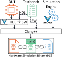
While promising, why has CDG not seen widespread adoption in hardware DV? As Laeufer et al. point out [15], this is likely fueled by several key technical challenges, resulting from dissimilarities between software and hardware execution models. First, unlike software, Register Transfer Level (RTL) hardware is not inherently executable. Hardware designs must be simulated, after being translated to a software model and combined with a design-specific testbench and simulation engine, to form a Hardware Simulation Binary (HSB) (Fig. 2). This level of indirection, increases both the complexity and computational effort in tracing test coverage of the hardware. Second, unlike most software, hardware requires sequences of structured inputs to drive meaningful state transitions, that must be tailored to each DUT. For example, while most software often accepts input in the form of a fixed set of file(s) that contain a loosely-structured set of bytes (e.g., a JPEG or PDF), hardware often accepts input from an ongoing stream of bus transactions. Together, these challenges have resulted in CDG approaches that implement custom: 1) coverage-tracing techniques that still suffer from poor scalability [15, 25], and 2) test generators that have limited compatibility to a small class of DUTs, e.g., processors [16, 32, 18].
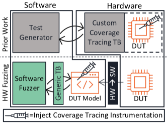
To supplement traditional dynamic verification methods, we propose an alternative CDG technique we call Hardware Fuzzing. Rather than translating software testing methods to the hardware domain, we advocate for translating hardware designs to software models and fuzzing those models directly (Fig. 1). While fuzzing hardware in the software domain eliminates coverage-tracing bottlenecks of prior CDG techniques [15, 16, 25], since software can be instrumented at compile time to trace coverage, it does not inherently solve the design compatibility issue. Moreover, it creates other challenges we must address. Specifically, to fuzz hardware like software, we must adapt software fuzzers to:
- 1.
-
2.
account for differences between how hardware and software process inputs, and its impact on exploration depth.
-
3.
design a general-purpose fuzzing harness and a suitable grammar that ensures meaningful mutation.
To address these challenges, we first propose (and evaluate) strategies for interfacing software fuzzers with HSBs that optimize performance and trigger the HSB to crash upon detection of incorrect hardware behavior. Second, we show that maximizing code coverage of the DUT’s software model, by construction, maximizes hardware code coverage. Third, we design an interface to map fuzzer-generated test-cases to hardware input ports. Our interface is built on the observation that unlike most software, hardware requires piecing together a sequence of inputs to effect meaningful state transitions. Lastly, we propose a new interface for fuzzing hardware in a design agnostic manner: the bus interface. Moreover, we design and implement a generic harness, and create a corresponding grammar that ensures meaningful mutations to fuzz bus transactions. Fuzzing at the bus interface solves the final hurdle to realizing widespread deployability of CDG in hardware DV, as it enables us to reuse the same testbench harness to fuzz any RTL hardware that speaks the same bus protocol, irrespective of the DUT’s design or implementation.
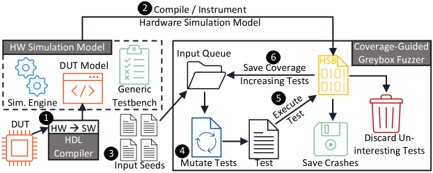
To demonstrate the effectiveness of our approach, we design, implement, and open-source a Hardware Fuzzing Pipeline (HWFP) [33], inspired by Google’s OSS-Fuzz [34], capable of fuzzing RTL hardware at scale (Fig. 5). Using our HWFP we compare Hardware Fuzzing against a conventional CRV technique when verifying over 480 variations of a sequential FSM circuit. Across our experiments, we observe over two orders-of-magnitude reduction in time to reach full FSM coverage by fuzzing hardware like software. Moreover, using our bus-specific hardware fuzzing grammar, we fuzz four commercial IP cores from Google’s OpenTitan silicon Root-of-Trust (RoT) [35]. Even without seeding the fuzzer, we achieve over 88% HDL line coverage after only 1-hour of fuzzing on three of the four cores.
In summary, we:
- •
- •
-
•
develop a technique to map fuzzer-generated testcases across both space and time to create a sequence of inputs to stimulate software models of hardware (§III-B2);
- •
- •
- •
II Background
There are two main hardware verification methods: 1) dynamic and 2) formal. While there have been significant advancements in deploying formal methods in DV workflows [36, 35, 32], dynamic verification remains the gold standard due to its scalability towards complex designs [15]. Therefore, we focus on improving dynamic verification by leveraging advancements in the software fuzzing community. Below, we provide a brief overview of the current state-of-the-art in dynamic hardware verification, and software fuzzing.
II-A Dynamic Verification of Hardware
Dynamic verification of hardware typically involves three steps: 1) test generation, 2) hardware simulation, and 3) test evaluation. First, during test generation, a sequence of inputs are crafted to stimulate the DUT. Next, the DUT’s behavior—in response to the input sequence—is simulated during hardware simulation. Lastly, during test evaluation, the DUT’s simulation behavior is checked for correctness. These three steps are repeated until all interesting DUT behaviors have been explored. How do we know when we have explored all interesting behaviors? To answer this question, verification engineers measure coverage of both: 1) manually defined functional behaviors (functional coverage) and 2) the HDL implementation of the design (code coverage) [37, 38, 39].
II-A1 Test Generation
To maximize efficiency, DV engineers aim to generate as few test vectors as possible that still close coverage. To achieve this goal, they deploy two main test generation strategies: 1) constrained-random and 2) coverage-directed. The former is typically referred to holistically as Constrained Random Verification (CRV), and the latter as Coverage Directed Test Generation (CDG). CRV is a partially automated test generation technique where manually-defined input sets are randomly combined into transaction sequences [26, 27]. While better than an entirely manual approach, CRV still requires some degree of manual tuning to avoid inefficiencies, since the test generator has no knowledge of test coverage. Regardless, CRV remains a popular dynamic verification technique today, and its principles are implemented in two widely deployed (both commercially and academically) hardware DV frameworks: 1) Accellera’s Universal Verification Methodology (UVM) framework (SystemVerilog) [27] and 2) the open-source cocotb (Python) framework [40].
To overcome CRV shortcomings, researchers have proposed CDG [22, 24, 25, 28, 29, 30, 15, 31, 32, 18, 17, 16], or using test coverage feedback to drive future test generation. Unlike CRV, CDG does not randomly piece input sequences together in hopes of exploring new design state. Rather, it mutates prior input sequences that explore uncovered regions of the design to iteratively expand the coverage boundary. Unfortunately, due to deployability challenges, e.g., slow coverage tracing and limited applicability to a small set of DUTs, CDG has not seen widespread adoption in practice [15]. In this paper, we recognize that existing software fuzzers provide a solution to many of these deployability challenges, and therefore advocate for verifying hardware using software verification tools. The central challenges in making this possible are adapting software fuzzers to verify hardware, widening the scope of supported designs, and increasing automation of verification.
 \cprotect
II-A2 Hardware Simulation
While there are several commercial [45, 46, 47] and open-source [41, 48] hardware simulators, most work in the same general manner, as shown in Fig. 2. First, they translate hardware implementations (described in HDL) into a software model, usually in C/C++. Next, they compile the software model and a testbench—either translated from HDL, or implemented in software (C/C++)—and link them with a simulation engine. Together, all three components form an Hardware Simulation Binary (HSB) (Fig. 2) that can be executed to simulate the design. Lastly, the HSB is executed with the inputs from the testbench to capture the design’s behavior. Ironically, even though commercial simulators convert the hardware to software, they still rely on hardware-specific verification tools, likely because software-oriented tools fail to work on hardware models—without the lessons in this paper. To fuzz hardware in the software domain, we take advantage of the transparency in how an open-source hardware simulator, Verilator [41], generates an HSB. Namely, we intercept the software model of the hardware after translation, and instrument/compile it for coverage-guided fuzzing (Fig. 3).
II-A3 Test Evaluation
After simulating a sequence of test inputs, the state of the hardware (both internally and its outputs) are evaluated for correctness. There are two main approaches for verifying design correctness: 1) invariant checking and 2) (gold) model checking. In invariant checking, a set of assertions (e.g., SystemVerilog Assertions or software side C/C++ assertions) are used to check properties of the design have not been violated. In model checking, a separate model of the DUT’s correct behavior is emulated in software, and compared to the DUT’s simulated behavior. We support such features and adopt both invariant violations and golden model mismatches as an analog for software crashes in our hardware fuzzer.
II-B Software Fuzzing
Software fuzzing is an automated testing technique designed to identify security vulnerabilities in software [49]. Thanks to its success, it has seen widespread adoption in both industry [50] and open-source [34] projects. In principle, fuzzing typically involves the following three main steps [51]: 1) test generation, 2) monitoring test execution, and 3) crash triaging. During test generation, program inputs are synthesized to exercise the target binary. Next, these inputs are fed to the program under test, and its execution is monitored. Lastly, if a specific test causes a crash, that test is further analyzed to find the root cause. This process is repeated until all, or most, of the target binary has been explored. Below we categorize fuzzers by how they implement the first two steps.
II-B1 Test Generation
Most fuzzers generate test cases in one of two ways, using: 1) a grammar, or 2) mutations. Grammar-based fuzzers [52, 53, 54, 55, 56, 57] use a human-crafted grammar to constrain tests to comply with structural requirements of a specific target application. Alternatively, mutational fuzzers take a correctly formatted test as a seed, and apply mutations to the seed to create new tests. Moreover, mutational fuzzers are tuned to be either: 1) directed, or 2) coverage-guided. Directed mutational fuzzers [58, 59, 60, 61, 62, 63, 64] favor mutations that explore specific region within the target binary, i.e., prioritizing exploration location. Conversely, coverage-guided mutational fuzzers [42, 43, 44, 65, 66, 67] favor mutations that explore as much of the target binary as possible, i.e., prioritizing exploration completeness. For this work, we favor the use of mutational, coverage-guided fuzzers, as they are both design-agnostic, and regionally generic.
II-B2 Test Execution Monitoring
Fuzzers monitor test execution using one of three approaches: 1) blackbox, 2) whitebox, or 3) greybox. Fuzzers that only monitor program inputs and outputs are classified as blackbox fuzzers [68, 52, 55]. Alternatively, fuzzers that track detailed execution paths through programs with fine-grain program analysis (source code required) and constraint solving are known as whitebox fuzzers [69, 70, 71, 72, 73, 74, 75, 64]. Lastly, greybox fuzzers [42, 58, 59, 44, 65, 54, 62, 63, 56, 57, 66, 76, 77, 67] offer a trade-off between black- and whitebox fuzzers by deploying lightweight program analysis techniques, such as code-coverage tracing. Since Verilator [41] produces raw C++ source code from RTL hardware, our approach can leverage any software fuzzing technique—white, grey, or blackbox. In our current implementation, we deploy greybox fuzzing, due to its popularity in the software testing community.
III Hardware Fuzzing
To take advantage of advances in software fuzzing for hardware DV, we propose translating hardware designs to software models, and fuzzing the model directly. We call this approach, Hardware Fuzzing, and illustrate the process in Fig. 3. Below, we first motivate our approach by describing how hardware is already translated to the software domain for simulation, and that software fuzzers provide a solution to a key technical challenge in CDG: scalable coverage tracing. Then, we pose several challenges in adapting software fuzzers to fuzz HSBs (in a design-agnostic fashion), and present solutions to overcome these challenges.
III-A Why Fuzz Hardware like Software?
We observe two key benefits of fuzzing hardware in the software domain. First, hardware is already translated to a software model for simulation purposes (§II-A2). Second, unlike prior CDG approaches [15, 16], we recognize that software fuzzers already provide an efficient solution for tracing coverage. Below we explain how RTL hardware is translated to executable software, and why software fuzzers implicitly maximize hardware coverage by generating tests that maximize coverage of the HSB.
III-A1 Translating HDL to Software
Today, simulating RTL hardware involves translating HDL into a functionally equivalent software (C/C++) model that can be compiled and executed (§II-A2). To accomplish this, most hardware simulators [48, 41] contain an RTL compiler to perform the translation. Therefore, we leverage a popular open-source hardware simulator, Verilator [41], to translate SystemVerilog HDL into a cycle-accurate C++ model for fuzzing.
Like many compilers, Verilator first performs lexical analysis and parsing (of the HDL) with the help of Flex [78] and Bison [79], to generate an Abstract Syntax Tree (AST). Then, it performs a series of passes over the AST to resolve parameters, propagate constants, replace don’t cares (Xs) with random values, eliminate dead code, unroll loops/generate statements, and perform several other optimizations. Finally, Verilator generates C++ (or SystemC) code representing a cycle-accurate model of the hardware. It creates a C++ class for each Verilog module, and organizes classes according to the original HDL module hierarchy [32].
To interface with the model, Verilator exposes public member variables for each input/output
to the top-level module, and a public eval() method (to be called in a loop) in
the top C++ class. Each input/output member variable is mapped to single/arrayed bool,
uint32_t, or uint64_t data types, depending on the width of each signal.
Each call to eval() updates the model based on the current values assigned to
top-level inputs and internal states variables. Two calls represent a single clock cycle
(one call for each rising and falling clock edges).
III-A2 Tracing Hardware Coverage in Software
To efficiently explore a DUT’s state space, CDG techniques rely on tracing coverage of past test cases to generate future test cases. There are two main categories of coverage metrics used in hardware verification [37, 38, 39]: 1) code coverage, and 2) functional coverage. The coarsest, and most used, code coverage metric is line coverage. Line coverage measures the percentage of HDL lines that have been exercised during simulation. Alternatively, functional coverage measures the percentage of various high-level design functionalities—defined using special HDL constructs like SystemVerilog Coverage Points/Groups—that are exercised during simulation. Regardless of the coverage metric used, tracing HDL coverage during simulation is often slow, since coverage traced in the software (simulation) domain must be mapped back to the hardware domain [38].
In an effort to compute DUT coverage efficiently, and in an HDL-agnostic manner, prior CDG techniques develop custom coverage metrics, e.g., multiplexer coverage [15], that can be monitored by instrumenting the RTL directly. However, this approach has two drawbacks. First, the hardware must be simulated on an FPGA (simulating within software is just as slow). Second, the authors provide no indication that their custom coverage metrics actually translate to coverage metrics DV engineers care about.
Rather than make incremental improvements to existing CDG techniques, we recognize that: 1) software fuzzers provide an efficient mechanism—e.g., binary instrumentation—to trace coverage of compiled C++ hardware models (HSBs), and 2) characteristics of how Verilator translates RTL hardware to software makes mapping software coverage to hardware coverage implicit. On the software side, there are three main code coverage metrics of increasing granularity: 1) basic block, 2) basic block edges, and 3) basic block paths [51]. The most popular coverage-guided fuzzers—AFL [42], libFuzzer [43], and honggfuzz [44]—all trace edge coverage. On the hardware side, Verilator conveniently generates straight-line C++ code for both blocking and non-blocking222Verilator imposes an order on the non-blocking assignments since C++ does not have a semantically equivalent assignment operator [41, 32]. Regardless, this ordering does not effect code coverage. SystemVerilog statements [32], and injects conditional code blocks (basic blocks) for SystemVerilog Assertions and Coverage Points. Therefore, optimizing test-generation edge coverage of the software model of the hardware during simulation, translates to optimizing both code and functional coverage of the hardware itself. We demonstrate this artifact in §VI-B3 of our evaluation.
III-B Adapting Software Fuzzers to Fuzz Hardware
While software fuzzers contain efficient mechanisms for tracing coverage of HSBs—e.g., binary instrumentation—interfacing them with HSBs, in a design-agnostic manner is non-trivial. Below, we highlight several challenges in fuzzing HSBs with software fuzzers, and propose solutions to overcome them.
III-B1 Interfacing Software Fuzzers with HSBs
Naïvely, a DV engineer may interface the HSB directly with a software fuzzer (like [42, 43, 44]) by compiling the HSB source code alongside the testbench harness (Algo. 1) and simulation engine with one of the fuzzer-provided wrappers for Clang. However, they would be ignoring two key differences between typical software applications and HSBs that may degrade fuzzer performance. First, HSBs have other components—a testbench and simulation engine (Fig. 2)—that are not part of the DUT. While the DUT is manipulated through the testbench and simulation engine, instrumenting all components HSBs actually degrades fuzzer performance (§V-C1). Additionally, unlike software, the DUT software model must be reset and initialized, prior to processing any inputs. Depending on the size of the DUT, this process can require special configuration of the testbench, i.e., initializing the fuzzer to snapshot the hardware simulation process after reset and initialization of the DUT (§V-C2).
III-B2 Interpreting Fuzzer-Generated Tests
For most software, a single input often activates an entire set of state transitions within the program.
Consequently, the most popular software fuzzers assume the target binary reads a single dimensional
input—e.g., a single image or document—from either a file, stdin, or a byte
array [42, 44, 43]. Unfortunately, the execution model of hardware is different.
In an HSB, a sequence of inputs is required to activate
state transitions within the DUT. For example, a 4-digit lock (with a keypad) only has a
chance of unlocking if a sequence of four inputs (test cases) are provided. Fuzzing this
lock with single test cases (digits), will fail. Likewise, fuzzing HSBs with software fuzzers
that employ a single-test-case-per-file model will also fail.
Therefore, to stimulate hardware with software fuzzers, we propose a new interface for interpreting
single dimensional fuzzer-generated tests in two dimensions: space and time. We implement
this interface in the form of a generic fuzzing harness (testbench)—shown in
Algo. 1—that continuously: 1) reads byte-level portions of
fuzzer-generated test files, 2) maps these bytes to hardware input ports, and 3) advances
the simulation clock by calling the model’s eval() method twice, until there are
no remaining bytes to process. With our fuzzing harness, we transform one-dimensional
test inputs, into a two-dimensional sequence of inputs.
III-B3 Bus-Centric Harness
While the multi-dimensional fuzzing interface we develop enables fuzzer-generated tests to effect state transitions in hardware, it is not design-agnostic. Specifically, the ports of a hardware model are not iterable (Algo. 1: line 4). A DV engineer would have to create a unique fuzz harness (testbench) for each DUT they verify. To facilitate DUT portability, we take inspiration from how hardware engineers interface IP cores within an SoC [80]. Specifically, we propose fuzzing IP cores at the bus interface using a bus-centric harness.
To implement this harness, we could alter our prior harness (Algo. 1) by mapping bytes from fuzzer-generated test files to temporal values for specific signals of a bus-protocol of our choice. However, this would create an exploration barrier since bus-protocols require structured syntax, and most mutational fuzzers lack syntax awareness [81]. In other words, the fuzzer would likely get stuck trying to synthesize a test file, that when mapped to spatio-temporal bus signal values, produces a valid bus-transaction. Instead, we implement a harness that decodes fuzzer-generated test files into sequences of properly structured bus transactions using a bus-centric grammar we describe below. Our current bus-centric harness is implemented around the TileLink Uncached Lightweight (TL-UL) bus protocol [82] with a 32-bit data bus, and illustrated in Fig. 12.
III-B4 Bus-Centric Grammar
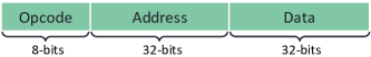
To translate fuzzer-generated test files into valid bus transactions we construct a Hardware Fuzzing grammar. We format our grammar in a compact binary representation to facilitate integration with popular greybox fuzzers that produce similar formats [42, 43, 44]. To match our bus-centric harness, we implement our grammar around the same TL-UL bus protocol [82]. Our grammar consists of Hardware Fuzzing instructions (Fig. 4), that contain: 1) an 8-bit opcode, 2) 32-bit address field, and 3) 32-bit data field. The opcode within each instruction determines the bus transaction the harness performs. We describe the mappings between opcodes and TL-UL bus transactions in Table I.
Note, there are two properties of our grammar that leave room for various harness (testbench) implementations, which we study in §VI-B. First, while we define only three opcodes in our grammar, we represent the opcode with an entire byte, leaving it up to the harness to decide how to map Hardware Fuzzing opcode values to testbench actions. We do this for two reasons: 1) a byte is the smallest addressable unit in most software, facilitating the development of utilities to automate generating compact binary seed files (that comply with our grammar) from high-level markdown languages, and 2) choosing a larger opcode field enables adding more opcodes in the future, should we need to support additional operations in TileLink bus protocol[82]. Second, of the three opcodes we include, not all require address and data fields. Therefore, it is up to the harness to decide how it should process Hardware Fuzzing instructions. Should it read fixed size instruction frames? Or variable size instructions frames, depending on the opcode? To understand which interpretation of our Hardware Fuzzing grammar provides optimal constraints for greybox fuzzing, we study the performance of various binary encodings of our grammar in §VI-B.
| Opcode |
|
|
Testbench Action | ||||
|---|---|---|---|---|---|---|---|
| wait | no | no | advance the clock one period | ||||
| read | yes | no | TL-UL Get (read) | ||||
| write | yes | yes | TL-UL PutFullData (write) |
IV Hardware Fuzzing Pipeline
 \cprotect
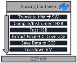
To fuzz hardware at scale we design, implement, and open-source [33] a Hardware Fuzzing Pipeline (HWFP) modeled after Google’s OSS-Fuzz (Fig. 5). First, our pipeline builds a Docker image (from the Ubuntu 20.04 base image) containing a compiler (LLVM version 12.0.0), RTL simulator (Verilator [41] version 4.0.4), software fuzzer, the target RTL hardware, and a generic fuzzing harness (§III-B3). From the image, a container is instantiated on a GCP VM that:
- 1.
- 2.
-
3.
launches the fuzzer for a set period of time, using the
timeoututility, - 4.
-
5.
saves fuzzing and coverage data to a Google Cloud Storage (GCS) bucket, and lastly
-
6.
tears down the VM.
Note, for benchmarking, all containers are instantiated on their own
GCP n1-standard-2 VM with two vCPUs, 7.5 GB of memory,
50 GB of disk, running Google’s Container-Optimized OS.
In our current implementation, we use AFL [42] (version 2.57b) as our fuzzer,
but our HWFP is designed to be fuzzer-agnostic.
Unlike traditional hardware verification toolchains, our HWFP uses only open-source tools, allowing DV engineers to save money on licenses, and spend it on compute. This not only enhances the deployability of our approach, but makes it ideal for adopting alongside existing hardware DV workflows. This is important because rarely are new DV approaches adopted without some overlap with prior (proven) techniques, since mistakes during hardware verification have costly repercussions.
V Evaluation - Part 1
In the first part of our evaluation, we address two technical questions around fuzzing software models of RTL hardware with software fuzzers. First, how should we interface coverage-guided software fuzzers with HSBs? Unlike most software, HSBs contain other components—a testbench and simulation engine (Fig. 2)—that are not the target of testing, yet the fuzzer must learn to manipulate in order to drive the DUT. Second, how does Hardware Fuzzing compare with traditional dynamic verification methods, i.e., CRV, in terms of time to coverage convergence? To address this first set of questions, we perform several End-to-End (E2E) fuzzing analyses on over 480 digital lock hardware designs with varying state-space complexities.
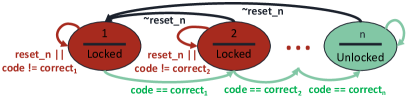
V-A Digital Lock Hardware
In this half of our evaluation, we fuzz various configurations of a digital
lock, whose FSM and HDL are shown in Fig. 6 and
List. 1, respectively. We choose to study this design since the
complexity of its state space is configurable, and therefore, ideal for stress testing
various DV methodologies. Specifically, the complexity is configurable in two
dimensions: 1) the total number of states is configurable by tuning the size, ,
of the single state register, and 2) the probability of choosing the correct
unlocking code sequence is adjustable by altering the size, , of the
comparator/mux that checks input codes against hard-coded (random) values
(List. 1). We develop a utility in Rust, using the kaze
crate [83], to auto-generate 480 different lock state machines of various
complexities, i.e., different values of , , and random correct code
sequences.
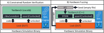
V-B Digital Lock HSB Architectures
To study these designs, we construct two HSB architectures (Fig. 7) using two hardware DV methodologies: CRV and Hardware Fuzzing. The CRV architecture (Fig. 7A) attempts to unlock the lock through a brute-force approach, where random code sequences are driven into the DUT until the unlocked state is reached. If the random sequence fails to unlock the lock, the DUT is reset, and a new random sequence is supplied. If the sequence succeeds, an SVA is violated, which terminates the simulation. The random code sequences are constrained in the sense that only valid code sequences are driven into the DUT, i.e., 1) each code in the sequence is in the range for locks with -bit code comparators, and 2) sequences contain exactly input codes for locks with states. The CRV testbench is implemented with the cocotb [40] framework and simulations are run with Verilator [41].
Alternatively, the Hardware Fuzzing HSB (Fig. 7B) takes input from a software fuzzer that generates code sequences for the DUT. The fuzzer initializes and checkpoints, a process running the HSB (Fig. 2), and repeatedly forks this process and tries various code sequence inputs. If an incorrect code sequence is supplied, the fuzzer forks a new process (equivalent to resetting the DUT) and tries again. If the correct code sequence is provided, an SVA is violated, which the fuzzer registers as a program crash. The difference between CRV and Hardware Fuzzing is that the fuzzer traces coverage during hardware simulation, and will save past code sequences that get closer to unlocking the lock. These past sequences are then mutated to generate future sequences. Thus, past inputs are used to craft more intelligent inputs in the future. To interface the software fuzzer with the HSB, we:
-
1.
implement a C++ testbench harness from Algo. 1 that reads fuzzer-generated bytes from
stdinand feeds them directly to thecodeinput of the lock. - 2.
V-C Interfacing Software Fuzzers with Hardware
There are two questions that arise when interfacing software fuzzers with HSBs. First, unlike most software applications, software models of hardware are not standalone binaries. They must be combined—typically by either static or dynamic linking—with a testbench and simulation engine to form an HSB (§II-A2). Of these three components—DUT, testbench, and simulation engine—we seek to maximize coverage of only the DUT. We do not want to waste fuzzing cycles on the testbench or simulation engine. Since coverage tracing instrumentation provides an indirect method to coarsely steer the fuzzer towards components of interest [58], it would be considered good practice to instrument just the DUT portion of the HSB. However, while the DUT is ultimately what we want to fuzz, the fuzzer must learn to use the testbench and simulation engine to manipulate the DUT. Therefore, what components of the HSB should we instrument to maximize fuzzer performance, yet ensure coverage convergence?
Second, when simulating hardware, the DUT must be reset to a clean state before it can start processing inputs. Traditionally, the testbench portion of the HSB performs this reset by asserting the DUT’s global reset signal for a set number of clock cycles. Since the fuzzer instantiates, and repeatedly forks the process executing the HSB, this reset process will happen hundreds, or (potentially) thousands of times per second as each test execution is processed. While some software fuzzers [42, 43] enable users to perform initialization operations before the program under test is forked—meaning the DUT reset could be performed once, as each forking operation essentially sets the HSB back to a clean state—-this may not always the case. Moreover, it complicates fuzzer–HSB integration, which contradicts the whole premise of our approach, i.e., low-overhead, design-agnostic CDG. Therefore, we ask: is this fuzzing initialization feature required to fuzz HSBs?
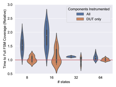
V-C1 Instrumenting HSBs for Fuzzing
To determine the components of the HSB we should instrument, we measure the fuzzing run times to achieve approximate full FSM coverage333We use the term approximate when referring to full FSM coverage, since we are not excising the lock’s reset state transitions (Fig. 6) in these experiments. of several lock designs, i.e., the time it takes the fuzzer to generate a sequence of input codes that unlocks each lock. We measure this by modifying the fuzzer to terminate upon detecting the first crash, which we produce using a single SVA that monitors the condition of the unlocked signal (List. 1). Specifically, using lock designs with 16, 32, and 64 states, and input codes widths of four bits, we construct HSBs following the architecture shown in Fig. 7B. For each HSB, we vary the components we instrument by using different compiler settings for each component. First, we (naïvely) instrument all components, then only the DUT. Next, we fuzz each HSB 50 times, seeding the fuzzer with an empty file in each experiment.
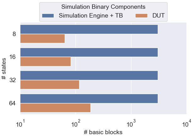
We plot the distribution of fuzzing run times in Fig. 8. Since fuzzing is an inherently random process, we plot only the middle third of run times across all instrumentation levels and lock sizes. Moreover, all run times are normalized to the median DUT-only instrumentation run times (orange) across each lock size. In addition to plotting fuzzing run times, we plot the number of basic blocks within each component of the HSB in Fig. 9. Across all lock sizes, we observe that only instrumenting the DUT does not handicap the fuzzer, but rather improves the rate of coverage convergence! In fact, we perform a Mann-Whitney U test, with a 0.05 significance level, and find all the run-time improvements to be statistically significant. Moreover, we observe that even though the run-time improvements are less significant as the DUT size increases compared to the simulation engine and testbench (Fig. 9), instrumenting only the DUT never handicaps the fuzzer performance.
 \cprotect
 \cprotect
V-C2 Hardware Resets vs. Fuzzer Performance
To determine if DUT resets present a performance bottleneck, we measure the
degradation in fuzzing performance due to the repeated simulation of DUT resets.
We take advantage of a unique feature of a popular greybox fuzzer [42] that
enables configuring the exact location of initializing the
fork server.444By default, AFL [42] instantiates a
process from the binary under test, pauses it, and repeatedly forks it to
create identical processes to feed test inputs to. The component
of AFL that performs process forking is known as the fork server.
This enables the fuzzer to perform any
program-specific initialization operations once, prior to forking children
processes to fuzz. Using this feature, we repeat the same fuzzing run time analysis
performed in §V-C1, except we instrument
all simulation binary components, and compare two variations of the digital lock
HSB shown in Fig. 7B. In one testbench, we use
the default fork server initialization location: at the start of main().
In the other testbench, we initialize the fork server after the point
where the DUT has been reset.
 \cprotect
 \cprotect
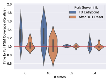
Fig. 10 shows our results. Again, we drop outliers by plotting only the middle third of run times across all lock sizes and fork server initialization points. Additionally, we normalize all run times to the median “after DUT reset” run times (orange) across each lock size. From these results, we apply the Mann-Whitney U test (with 0.05 significance level) between run times. This time, only locks with 8 and 16 states yield p-values less than 0.05. This indicates the overhead of continuously resetting the DUT during fuzzing diminishes as the DUT increases in complexity. Additionally, we note that even the largest digital locks we study (64 states), are smaller than the smallest OpenTitan core, the RISC-V Timer, in terms of number of basic blocks in the software model (Fig. 9 & Table II).
V-D Hardware Fuzzing vs. CRV
Using the techniques we learned from above, we perform a run-time comparison analysis between Hardware Fuzzing and CRV,555CRV is widely deployed in any DV testbenches built around the cocotb [40] or UVM [27] frameworks, e.g., all OpenTitan [35] IP core testbenches. the current state-of-the-art hardware dynamic verification technique. We perform these experiments using digital locks of various complexities, from 2 to 64 states, and code widths of 1 to 8 bits. The two HSB architectures we compare are shown in Fig. 7, and discussed in §V-B. Note, the fuzzer was again seeded with an empty file to align its starting state with the CRV tests.
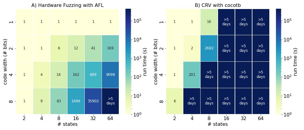
Similar to our instrumentation and reset experiments (§V-C) we measure the fuzzing run times required to achieve full FSM coverage of each lock design, i.e., the time to unlock each lock. We illustrate these run times in heatmaps shown in Fig. 11. We perform 20 trials for each experiment and average these run times in each square of a heatmap. While the difference between the two approaches is indistinguishable for extremely small designs, the advantages of Hardware Fuzzing become apparent as designs increase in complexity. For medium to larger lock designs, Hardware Fuzzing achieves full FSM coverage faster than CRV by over two orders-of-magnitude, even when the fuzzer is seeded with an empty file. Moreover, many CRV experiments were terminated early (after running for five days) to save money on GCP instances.
VI Evaluation - Part 2
In the second part of our evaluation, we address two remaining questions. First, how should we format our grammar to enable the fuzzer to learn it quickly? To facilitate widespread deployment of Hardware Fuzzing, it is imperative DV engineers do not have to tailor fuzzing harnesses (testbenches) to specific designs, as is the case with existing CDG methods [22, 24, 25, 28, 29, 30, 15]. Lastly, how does Hardware Fuzzing perform in practice on real hardware IP cores? To address these questions, we perform E2E fuzzing analyses on four commercial hardware cores from Google’s OpenTitan [35] SoC.
VI-A OpenTitan IP
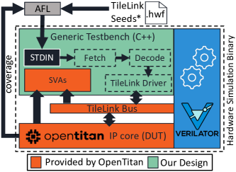
The four OpenTitan IP blocks we study are the: AES, HMAC, KMAC, and RISC-V Timer cores. While each core performs different functions, they all conform to the OpenTitan Comportability Specification [80], which implies they are all controlled via reads and writes to memory-mapped registers over a TL-UL bus. By adhering to a uniform bus protocol, we are able to re-use a generic fuzzing harness (Fig. 12), facilitating the deployability of our approach. Below, we highlight the functionality of each IP core. Additionally, in Table II, we report the complexity of each IP core in both the hardware and software domains, in terms of Lines of Code (LOC), number of basic blocks, and number of SVAs provided in each core’s HDL. Software models of each hardware design are produced using Verilator, as we describe in §III-A1.
 \cprotect
VI-A1 AES
The OpenTitan AES core implements the Advanced Encryption Standard with key sizes of 128, 192, and 256 bits, and with the following cipher block modes: ECB, CBC, CFB, OFB, and CTR. Configuration settings, keys, and plaintext are delivered to the core through TileLink write operations to memory-mapped registers in a documented address range. Likewise, ciphertext is retrieved from the core through TileLink read operations. The core targets medium performance (one clock cycle per round of encryption). It implements a 128-bit wide data path—shared by encryption and decryption operations—that translates to encryption/decryption latencies of 12, 14, and 16 clock cycles per 128-bit plaintext block, in 128, 192, and 256 bit key modes, respectively. Of the cores we study, it is the second most complex in terms of LOC in both the hardware (HDL) and software domains (Table II).
VI-A2 HMAC
The OpenTitan HMAC implements a SHA-256 hash message authentication code generator for the purpose of checking the integrity of incoming messages. The HMAC core can operate in two modes: 1) SHA-256 mode only, or 2) HMAC mode. In the former mode, the core simply computes the SHA-256 hash of a provided message. In the latter mode, the core computes the HMAC (defined in RFC 2104 [84]) of a message using the SHA-256 hashing algorithm and a provided secret key. Regardless of mode, the SHA-256 engine operates on 512-bit message chunks at any given time, provided to the core through a message FIFO. Input messages can be read little- or big-endian and likewise, message digests can be stored in output registers either little- or big-endian. Configuration settings, input messages, HMAC keys, and operation commands are delivered to the core through TileLink write operations to memory-mapped registers. Likewise, message digests are retrieved from the core through TileLink read operations. In its current state, the core can hash a single 512-bit message in 80 clock cycles, and can compute its HMAC in 340 clock cycles. Of the cores we study, it is approximately half as complex as the AES core, in terms of LOC in both the hardware and software domains (Table II).
VI-A3 KMAC
The OpenTitan KMAC core is similar to the HMAC core, except it implements a Keccak Message Authentication Code [85] and SHA-3 hashing algorithms. However, compared to the HMAC core, the KMAC core is more complex, as there are several more configurations. Specifically, there are many SHA-3 hashing functions that are supported—SHA3-224/256/384/512, SHAKE128/256, and cSHAKE128/256—and the function (by default) operates on 1600 bits of internal state. Like the HMAC core, the KMAC core can simply compute hashes or message authentication codes depending on operation mode, and input messages/output digests can be configured to be read/stored in little- or big-endian. The time to process a single input message block is dominated by computing the function, which takes 72 clock cycles for 1600 bits of internal state, in the current implementation of the core. Configuration settings, input messages, output digests, keys, and operation commands are all communicated to/from the core through TileLink writes/reads to memory-mapped registers.
Of the cores we study, the KMAC core is the most complex, especially in the software domain (Table II). The software model of the KMAC core contains almost 120k lines of C++ code. This is mostly an artifact of how Verilator maps dependencies between large registers and vectored signals: it creates large multidimensional arrays and maps each corresponding index at the word granularity. Fortunately, this artifact is optimized away during compilation, and the number of basic blocks in the DUT portion of the HSB is reduced.
VI-A4 RV-Timer
The OpenTitan RISC-V timer core is the simplest core we fuzz. It consists of a single 64-bit timer with 12-bit prescaler and an 8-bit step configurations. It can also generate system interrupts upon reaching a pre-configured time value. Like the other OpenTitan cores, the RV-Timer core is configured, activated, and deactivated via TileLink writes to memory-mapped registers.
VI-B Optimizing the Hardware Fuzzing Grammar
Recall, to facilitate widespread adoption of Hardware Fuzzing we design a generic testbench fuzzing harness that decodes a grammar and performs corresponding TL-UL bus transactions to exercise the DUT (Fig. 12). However, there are implementation questions surrounding how the grammar should be decoded (§III-B4):
-
1.
How should we decode 8-bit opcodes when the opcode space defines less than valid testbench actions?
-
2.
How should we pack Hardware Fuzzing instruction frames that conform to our grammar?
VI-B1 Opcode Formats
In its current state, we define three opcodes in our grammar that correspond to three actions our generic testbench can perform (Table I): 1) wait one clock cycle, 2) TL-UL read, and 3) TL-UL write. However, we chose to represent these opcodes with a single byte (Fig. 4). Choosing a larger field than necessary has implications regarding the fuzzability of our grammar. In its current state, 253 of the 256 possible opcode values may be useless depending on how they are decoded by the testbench. Therefore we propose, and empirically study, two design choices for decoding Hardware Fuzzing opcodes into testbench actions:
-
•
Constant: constant values are used to represent each opcode corresponding to a single testbench action. Remaining opcode values are decoded as invalid, and ignored.
-
•
Mapped: equal sized ranges of opcode values are mapped to valid testbench actions. No invalid opcode values exist.
VI-B2 Instruction Frame Formats
Of the three actions our testbench can perform—wait, read, and write—some require additional information. Namely, the TL-UL read action requires a 32-bit address field, and the TL-UL write action requires 32-bit data and address fields. Given this, there are two natural ways to decode Hardware Fuzzing instructions (Fig. 4):
-
•
Fixed: a fixed instruction frame size is decoded regardless of the opcode. Address and data fields could go unused depending on the opcode.
-
•
Variable: a variable instruction frame size is decoded. Address and data fields are only appended to opcodes that correspond to TL-UL read and write testbench actions. No address/data information goes unused.
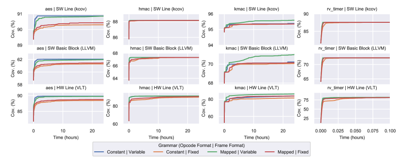
VI-B3 Results
To determine the optimal Hardware Fuzzing grammar, we fuzz four OpenTitan IP blocks—the
AES, HMAC, KMAC, and RV-Timer—for 24 hours
using all combinations of opcode and instruction frame formats mentioned above.
For each core we seed the fuzzer with 8–12 binary Hardware Fuzzing seed files
(in the corresponding Hardware Fuzzing grammar) that correctly drive each core, with the
exception of the RV-Timer core, which we seed with a single wait operation
instruction due to its simplicity. For each experiment, we extract and plot three
DUT coverage metrics over fuzz times in Fig. 13.
These metrics include: 1) line coverage of the DUT software model, 2) basic
block coverage of the same, and 3) line coverage of the DUT’s HDL.
Software line coverage is computed using kcov [86], software basic
block coverage is computed using LLVM [87], and hardware line coverage
is computed using Verilator [41]. Since we perform 10 repetitions
of each fuzzing experiment, we average and consolidate each coverage time series
into a single trace.
From these results we draw two conclusions. First, variable instruction frames seem to perform better than fixed frames, especially early in the fuzzing exploration. Since AFL prioritizes keeping test files small, we expect variable sized instruction frames to produce better results, since this translates to longer hardware test sequences, and therefore deeper possible explorations of the (sequential) state space. Second, the opcode type seems to make little difference, for most experiments, since there are only 256 possible values, a search space AFL can explore very quickly. Lastly, we point out that for simple cores, like the RV-Timer, Hardware Fuzzing is able to achieve 85% HDL line coverage in less than a minute (hence we do not plot the full 24-hour trace).
VI-C Hardware Fuzzing in Practice
Finally, we address the question: How does Hardware Fuzzing perform in practice? First, we show that with no knowledge of how to properly use the DUT, we achieve almost 90% HDL line coverage across the OpenTitan [35] cores we study. Second, we compare Hardware Fuzzing against the most popular DV technique today, CRV, demonstrating over two orders-of-magnitude faster coverage-convergence times.
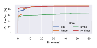 \cprotect
Unlike most software applications that are fuzzed [34], we observe that software models of hardware are quite small (Table II). So, we decided to experiment fuzzing each OpenTitan core we study for one hour, using a single empty seed file as starting input. We plot the results of this experiment in Fig. 14. After only one hour of fuzzing with no proper starting seeds, we achieve over 88% HDL line coverage across three of the four OpenTitan IP cores we study, and over 65% coverage of the remaining design.
VII Discussion
VII-1 Detecting Bugs During Fuzzing
The focus of Hardware Fuzzing is to provide a scalable yet flexible solution for integrating
CDG with hardware simulation. However, test generation and
hardware simulation comprise only two-thirds of the hardware verification
process (§II-A). The final, and
arguably most important, step is detecting incorrect hardware behavior, i.e.,
test evaluation in §II-A3.
For this there are two approaches: 1) invariant checking and 2) (gold) model checking.
In both cases, we trigger HSB crashes upon detecting incorrect hardware behavior,
which software fuzzers log. For invariant checks, we use SVAs that send the HSB
process the SIGABRT signal upon assertion violation. Likewise, for gold model
checking testbenches any mismatches between models results in a SIGABRT.
VII-2 Additional Bus Protocols
To provide a design-agnostic interface to fuzz RTL hardware, we develop a design-agnostic testbench harness (Fig. 12). Our harness decodes fuzzer-generated tests using a bus-specific grammar (§III-B4), and produces corresponding TL-UL bus transactions that drive a DUT. In our current implementation, our generic testbench harness conforms to the TL-UL bus protocol [82]. As a result, we can fuzz any IP core that speaks the same bus protocol (e.g., all OpenTitan cores [35]). To fuzz cores that speak other bus protocols (e.g., Wishbone, AMBA, Avalon, etc.), users can simply write a new harness for the bus they wish to support.
VII-3 Hardware without a Bus Interface
For hardware cores that perform I/O over a generic set of ports that do not conform to any bus protocol, we provide a generic testbench harness that maps fuzzer-generated input files across spatial and temporal domains by interpreting each fuzzer-generated file as a sequence of DUT inputs (Algo. 1). We demonstrate this Hardware Fuzzing configuration when fuzzing various digital locks (Fig. 7B). However, if inputs require any structural dependencies, we advise developing a grammar and corresponding testbench—similar to our bus-specific grammar (§III-B4)—to aid the fuzzer in generating valid test cases. Designers can use the lessons in this paper to guide their core-specific grammar designs.
VII-4 Limitations
While Hardware Fuzzing is both efficient and design-agnostic, there are some limitations. First, unlike software there is no notion of a hardware sanitizer, that can add safeguards against generic classes of hardware bugs for the fuzzer to sniff out. While we envision hardware sanitizers being a future active research area, for now, DV engineers must create invariants or gold models to check design behavior against for the fuzzer to find crashing inputs. Second, there is notion of analog behavior in RTL hardware, let along in translated software models. In its current implementation, Hardware Fuzzing is not effective against detecting side-channel vulnerabilities that rely on information transmission/leakage through analog domains.
VIII Related Work
There are two categories of prior CDG approaches: 1) design-agnostic and 2) design-specific.
VIII-1 Design-Agnostic
Laeufer et al. ’s RFUZZ [15] is the most relevant prior work,
which attempts to build a full-fledged design-agnostic RTL fuzzer. To achieve
their goal, they propose a new RTL coverage metric—mux toggle
coverage—that measures if the control signal to a 2:1 multiplexer expresses both
states (0 and 1). Unlike Hardware Fuzzing, they instrument the HDL directly, and develop
their own custom RTL fuzzer (Fig. 1). Unfortunately,
RFUZZ must be accelerated on FPGAs since coverage tracing is slow, and it is
unclear how their mux toggle coverage maps to existing RTL coverage
metrics DV engineers care about most, e.g., code coverage and functional
coverage [38, 37]. Gent et al. [17] propose an
automatic test pattern generator based on custom coverage metrics, for which they
also instrument the RTL directly to trace. Unfortunately, like RFUZZ, the
scalability of their approach remains in question, given their coverage tracing method,
and unlike RFUZZ, they do not accelerate their simulations on FPGAs.
VIII-2 Design-Specific
Unlike the design-agnostic approaches, the following work proposes CDG techniques exclusively for processors. Zhang et al. propose Coppelia [32], a tool that uses a custom symbolic execution engine (built on top of KLEE [70]) on software models of the RTL. Coppelia’s goal is to target specific security-critical properties of processors; Hardware Fuzzing enables combining such static methods with fuzzing (i.e., concolic execution [69]) for free, overcoming the limits of symbolic execution alone. Two other processor-specific CDG approaches are Squillero’s MicroGP [16] and Bose et al. ’s [18] that use a genetic algorithms to generate random assembly programs that maximize RTL code coverage of a processor. Unlike Hardware Fuzzing, these approaches require custom DUT-specific grammars to build assembly programs from.
IX Conclusion
Hardware Fuzzing is an effective solution to CDG for hardware DV. Unlike prior work, we take advantage of feature rich software testing methodologies and tools, to solve a longstanding problem in hardware DV. To make our approach attractive to DV practitioners, we solve several key deployability challenges, including developing generic interfaces (grammar & testbench) to fuzz RTL in a design- agnostic manner. Using our generic grammar and testbench, we demonstrate how Hardware Fuzzing can achieve over 88% HDL code coverage of three out of four commercial-grade hardware designs in only one hour, with no knowledge of the DUT design or implementation. Moreover, compared to standard dynamic verification practices, we achieve over two order-of-magnitude faster design coverage with Hardware Fuzzing.
Acknowledgment
We thank Scott Johnson, Srikrishna Iyer, Rupert Swarbrick, Pirmin Vogel, Philipp Wagner, and other members of the OpenTitan team for their technical expertise that enabled us to demonstrate our approach on the OpenTitan IP ecosystem.
References
- [1] G. E. Moore, “Cramming more components onto integrated circuits,” 1965.
- [2] R. H. Dennard, F. H. Gaensslen, V. L. Rideout, E. Bassous, and A. R. LeBlanc, “Design of ion-implanted mosfet’s with very small physical dimensions,” IEEE Journal of Solid-State Circuits, 1974.
- [3] T. Chen, Z. Du, N. Sun, J. Wang, C. Wu, Y. Chen, and O. Temam, “Diannao: A small-footprint high-throughput accelerator for ubiquitous machine-learning,” ACM SIGARCH Conference on Architectural Support for Programming Languages and Operating Systems (ASPLOS), 2014.
- [4] T. Nowatzki, V. Gangadhan, K. Sankaralingam, and G. Wright, “Pushing the limits of accelerator efficiency while retaining programmability,” in IEEE International Symposium on High Performance Computer Architecture (HPCA), 2016.
- [5] N. Jouppi, C. Young, N. Patil, and D. Patterson, “Motivation for and evaluation of the first tensor processing unit,” IEEE Micro, 2018.
- [6] R. Hameed, W. Qadeer, M. Wachs, O. Azizi, A. Solomatnikov, B. C. Lee, S. Richardson, C. Kozyrakis, and M. Horowitz, “Understanding sources of inefficiency in general-purpose chips,” in the 37th annual International Symposium on Computer Architecture (ISCA), 2010.
- [7] I. Magaki, M. Khazraee, L. V. Gutierrez, and M. B. Taylor, “ASIC clouds: Specializing the datacenter,” in 2016 ACM/IEEE 43rd Annual International Symposium on Computer Architecture (ISCA). IEEE, 2016, pp. 178–190.
- [8] S. Shao and E. Wang, “Die photo analysis,” http://vlsiarch.eecs.harvard.edu/research/accelerators/die-photo-analysis/.
- [9] M. Corporation, “Cve details: Intel: Vulnerability statistics,” August 2019, https://www.cvedetails.com/vendor/238/Intel.html.
- [10] P. Kocher, J. Horn, A. Fogh, , D. Genkin, D. Gruss, W. Haas, M. Hamburg, M. Lipp, S. Mangard, T. Prescher, M. Schwarz, and Y. Yarom, “Spectre attacks: Exploiting speculative execution,” in 40th IEEE Symposium on Security and Privacy (S&P’19), 2019.
- [11] M. Lipp, M. Schwarz, D. Gruss, T. Prescher, W. Haas, A. Fogh, J. Horn, S. Mangard, P. Kocher, D. Genkin, Y. Yarom, and M. Hamburg, “Meltdown: Reading kernel memory from user space,” in 27th USENIX Security Symposium (USENIX Security’18), 2018.
- [12] J. Van Bulck, M. Minkin, O. Weisse, D. Genkin, B. Kasikci, F. Piessens, M. Silberstein, T. F. Wenisch, Y. Yarom, and R. Strackx, “Foreshadow: Extracting the keys to the Intel SGX kingdom with transient out-of-order execution,” in 27th USENIX Security Symposium (USENIX Security’18), 2018.
- [13] S. van Schaik, A. Milburn, S. Österlund, P. Frigo, G. Maisuradze, K. Razavi, H. Bos, and C. Giuffrida, “RIDL: Rogue in-flight data load,” in 40th IEEE Symposium on Security and Privacy (S&P’19), 2019.
- [14] C. Canella, D. Genkin, L. Giner, D. Gruss, M. Lipp, M. Minkin, D. Moghimi, F. Piessens, M. Schwarz, B. Sunar, J. Van Bulck, and Y. Yarom, “Fallout: Leaking data on meltdown-resistant CPUs,” in ACM SIGSAC Conference on Computer and Communications Security (CCS), 2019.
- [15] K. Laeufer, J. Koenig, D. Kim, J. Bachrach, and K. Sen, “RFUZZ: coverage-directed fuzz testing of RTL on FPGAs,” in IEEE/ACM International Conference on Computer-Aided Design (ICCAD). IEEE, 2018.
- [16] G. Squillero, “Microgp—an evolutionary assembly program generator,” Genetic Programming and Evolvable Machines, 2005.
- [17] K. Gent and M. S. Hsiao, “Fast multi-level test generation at the rtl,” in 2016 IEEE Computer Society Annual Symposium on VLSI (ISVLSI), 2016.
- [18] M. Bose, J. Shin, E. M. Rudnick, T. Dukes, and M. Abadir, “A genetic approach to automatic bias generation for biased random instruction generation,” in Proceedings of the Congress on Evolutionary Computation. IEEE, 2001.
- [19] T. Kim, “Intel’s alleged security flaw could cost chipmaker a lot of money, Bernstein says,” https://www.cnbc.com/2018/01/03/intels-alleged-security-flaw-could-cost-chipmaker-a-lot-of-money-bernstein.html.
- [20] K. Yang, M. Hicks, Q. Dong, T. Austin, and D. Sylvester, “A2: Analog malicious hardware,” in IEEE Symposium on Security and Privacy (SP), 2016.
- [21] L.-T. Wang, Y.-W. Chang, and K.-T. T. Cheng, Electronic design automation: synthesis, verification, and test. Morgan Kaufmann, 2009.
- [22] S. Fine and A. Ziv, “Coverage directed test generation for functional verification using bayesian networks,” in the 40th annual Design Automation Conference (DAC), 2003.
- [23] D. Moghimi, B. Sunar, T. Eisenbarth, and N. Heninger, “TPM-FAIL: TPM meets Timing and Lattice Attacks,” in 29th USENIX Security Symposium (USENIX Security’20), 2020. [Online]. Available: https://www.usenix.org/conference/usenixsecurity20/presentation/moghimi
- [24] M. Cieplucha, “Metric-driven verification methodology with regression management,” Journal of Electronic Testing, 2019.
- [25] C. Ioannides, G. Barrett, and K. Eder, “Introducing xcs to coverage directed test generation,” in IEEE International High Level Design Validation and Test Workshop (HLDVT), 2011.
- [26] J. Yuan, C. Pixley, A. Aziz, and K. Albin, “A framework for constrained functional verification,” in International Conference on Computer Aided Design (ICCAD). IEEE, 2003.
- [27] Accellera, “Universal Verification Methodology (UVM),” https://www.accellera.org/downloads/standards/uvm.
- [28] M. Teplitsky, A. Metodi, and R. Azaria, “Coverage driven distribution of constrained random stimuli,” in Proceedings of the Design and Verification Conference (DVCon), 2015.
- [29] O. Guzey and L.-C. Wang, “Coverage-directed test generation through automatic constraint extraction,” in IEEE International High Level Design Validation and Test Workshop (HLDVT), 2007.
- [30] F. Wang, H. Zhu, P. Popli, Y. Xiao, P. Bodgan, and S. Nazarian, “Accelerating coverage directed test generation for functional verification: A neural network-based framework,” in Proceedings of the Great Lakes Symposium on VLSI, 2018.
- [31] R. Zhang and C. Sturton, “A recursive strategy for symbolic execution to find exploits in hardware designs,” in ACM SIGPLAN International Workshop on Formal Methods and Security (FSM), 2018.
- [32] R. Zhang, C. Deutschbein, P. Huang, and C. Sturton, “End-to-end automated exploit generation for validating the security of processor designs,” in 51st Annual IEEE/ACM International Symposium on Microarchitecture (MICRO). IEEE, 2018.
- [33] T. Trippel, “Hardware Fuzzing Pipeline,” https://github.com/googleinterns/hw-fuzzing.
- [34] K. Serebryany, “OSS-Fuzz - google’s continuous fuzzing service for open source software,” in USENIX Security Symposium, 2017.
- [35] lowRISC, “Opentitan,” https://opentitan.org/.
- [36] R. Kaivola, R. Ghughal, N. Narasimhan, A. Telfer, J. Whittemore, S. Pandav, A. Slobodová, C. Taylor, V. Frolov, E. Reeber et al., “Replacing testing with formal verification in intel core i7 processor execution engine validation,” in International Conference on Computer Aided Verification (CAV). Springer, 2009.
- [37] S. Tasiran and K. Keutzer, “Coverage metrics for functional validation of hardware designs,” IEEE Design & Test of Computers, 2001.
- [38] J.-Y. Jou and C.-N. J. Liu, “Coverage analysis techniques for hdl design validation,” Proceedings of Asia Pacific CHip Design Languages, 1999.
- [39] A. Piziali, Functional verification coverage measurement and analysis. Springer Science & Business Media, 2007.
- [40] P. Ventures, “cocotb,” https://github.com/cocotb/cocotb.
- [41] W. Snyder, “verilator,” https://www.veripool.org/wiki/verilator.
- [42] M. Zalewski, “American fuzzy lop,” https://lcamtuf.coredump.cx/afl/.
- [43] LLVM Project, “libFuzzer – a library for coverage-guided fuzz testing,” https://llvm.org/docs/LibFuzzer.html.
- [44] R. Swiecki, “honggfuzz,” https://honggfuzz.dev/.
- [45] Synopsys, “VCS,” https://www.synopsys.com/verification/simulation/vcs.html.
- [46] Mentor Graphics, “ModelSim,” https://www.mentor.com/products/fv/modelsim/.
- [47] Cadence Design Systems, “Xcelium Logic Simulation,” https://www.cadence.com/en\_US/home/tools/system-design-and-verification/simulation-and-testbench-verification/xcelium-simulator.html.
- [48] S. Williams, “Icarus Verilog,” http://iverilog.icarus.com/.
- [49] M. Sutton, A. Greene, and P. Amini, Fuzzing: brute force vulnerability discovery. Pearson Education, 2007.
- [50] E. Bounimova, P. Godefroid, and D. Molnar, “Billions and billions of constraints: Whitebox fuzz testing in production,” in 2013 35th International Conference on Software Engineering (ICSE). IEEE, 2013.
- [51] S. Nagy and M. Hicks, “Full-speed fuzzing: Reducing fuzzing overhead through coverage-guided tracing,” in Symposium on Security and Privacy (S&P). IEEE, 2019.
- [52] Mozilla Security, “Dharma: A generation-based, context-free grammar fuzzer,” https://www.overleaf.com/project/5e163844e63c070001079faa.
- [53] J. Johnson, “gramfuzz,” https://github.com/d0c-s4vage/gramfuzz.
- [54] C. Aschermann, T. Frassetto, T. Holz, P. Jauernig, A.-R. Sadeghi, and D. Teuchert, “NAUTILUS: Fishing for deep bugs with grammars.” in Network and Distributed Systems Security Symposium (NDSS), 2019.
- [55] Peach Tech, “Peach Fuzzing Platform,” https://www.peach.tech/products/peach-fuzzer/.
- [56] J. Wang, B. Chen, L. Wei, and Y. Liu, “Skyfire: Data-driven seed generation for fuzzing,” in IEEE Symposium on Security and Privacy (S&P), 2017.
- [57] ——, “Superion: Grammar-aware greybox fuzzing,” in IEEE/ACM International Conference on Software Engineering (ICSE), 2019.
- [58] M. Böhme, V.-T. Pham, and A. Roychoudhury, “Coverage-based greybox fuzzing as markov chain,” IEEE Transactions on Software Engineering, 2017.
- [59] P. Zong, T. Lv, D. Wang, Z. Deng, R. Liang, and K. Chen, “FuzzGuard: Filtering out unreachable inputs in directed grey-box fuzzing through deep learning,” in USENIX Security Symposium, 2020.
- [60] H. Chen, Y. Xue, Y. Li, B. Chen, X. Xie, X. Wu, and Y. Liu, “Hawkeye: Towards a desired directed grey-box fuzzer,” in ACM SIGSAC Conference on Computer and Communications Security (CCS), 2018.
- [61] C. Aschermann, S. Schumilo, A. Abbasi, and T. Holz, “Ijon: Exploring deep state spaces via fuzzing,” in IEEE Symposium on Security and Privacy (S&P), 2020.
- [62] S. Österlund, K. Razavi, H. Bos, and C. Giuffrida, “ParmeSan: Sanitizer-guided greybox fuzzing,” in USENIX Security Symposium, 2020.
- [63] W. You, P. Zong, K. Chen, X. Wang, X. Liao, P. Bian, and B. Liang, “Semfuzz: Semantics-based automatic generation of proof-of-concept exploits,” in ACM SIGSAC Conference on Computer and Communications Security (CCS), 2017.
- [64] T. Wang, T. Wei, G. Gu, and W. Zou, “TaintScope: A checksum-aware directed fuzzing tool for automatic software vulnerability detection,” in IEEE Symposium on Security and Privacy (S&P), 2010.
- [65] K. Serebryany, “Continuous fuzzing with libfuzzer and addresssanitizer,” in Cybersecurity Development (SecDev). IEEE, 2016.
- [66] D. Vyukov, “syzkaller,” https://github.com/google/syzkaller.
- [67] S. Rawat, V. Jain, A. Kumar, L. Cojocar, C. Giuffrida, and H. Bos, “VUzzer: Application-aware evolutionary fuzzing,” in Network and Distributed Systems Security Symposium (NDSS), 2017.
- [68] M. Vuagnoux, “Autodaf´e: an act of software torture,” http://autodafe.sourceforge.net/tutorial/index.html.
- [69] N. Stephens, J. Grosen, C. Salls, A. Dutcher, R. Wang, J. Corbetta, Y. Shoshitaishvili, C. Kruegel, and G. Vigna, “Driller: Augmenting fuzzing through selective symbolic execution.” in Network and Distributed Systems Security Symposium (NDSS), 2016.
- [70] C. Cadar, D. Dunbar, D. R. Engler et al., “KLEE: Unassisted and automatic generation of high-coverage tests for complex systems programs.” in USENIX Symposium on Operating Systems Design and Implementation (OSDI), 2008.
- [71] S. K. Cha, T. Avgerinos, A. Rebert, and D. Brumley, “Unleashing mayhem on binary code,” in IEEE Symposium on Security and Privacy (S&P), 2012.
- [72] H. Huang, P. Yao, R. Wu, Q. Shi, and C. Zhang, “PANGOLIN: Incremental hybrid fuzzing with polyhedral path abstraction,” in IEEE Symposium on Security and Privacy (S&P), 2020.
- [73] I. Yun, S. Lee, M. Xu, Y. Jang, and T. Kim, “QSYM: A practical concolic execution engine tailored for hybrid fuzzing,” in USENIX Security Symposium, 2018.
- [74] V. Chipounov, V. Kuznetsov, and G. Candea, “S2E: A platform for in-vivo multi-path analysis of software systems,” ACM SIGPLAN International Conference on Architectural Support for Programming Languages and Operating Systems (ASPLOS), 2011.
- [75] P. Godefroid, M. Y. Levin, and D. Molnar, “SAGE: whitebox fuzzing for security testing,” Queue, 2012.
- [76] H. Peng, Y. Shoshitaishvili, and M. Payer, “T-fuzz: fuzzing by program transformation,” in IEEE Symposium on Security and Privacy (S&P), 2018.
- [77] J. Hertz and T. Newsham, “ProjectTriforce: AFL/QEMU fuzzing with full-system emulation,” https://github.com/nccgroup/TriforceAFL.
- [78] V. Paxson, W. Estes, and J. Millaway, “Lexical analysis with flex,” University of California, 2007.
- [79] The GNU Project, “Bison,” https://www.gnu.org/software/bison/.
- [80] l. Contributors, “OpenTitan: Comportability Definition and Specification,” November 2020, https://docs.opentitan.org/doc/rm/comportability_specification/.
- [81] M. Zalewski, “afl-fuzz: making up grammar with a dictionary in hand,” https://lcamtuf.blogspot.com/2015/01/afl-fuzz-making-up-grammar-with.html.
- [82] S. Inc., “SiFive: TileLink Specification,” November 2020, version 1.8.0.
- [83] J. Taylor, “Kaze: an HDL embedded in Rust,” November 2020, https://docs.rs/kaze/0.1.13/kaze/.
- [84] H. Krawczyk, M. Bellare, and M. Bellare, “HMAC: Keyed-hashing for message authentication,” RFC Editor, RFC 2104, February 1997. [Online]. Available: \url{https://www.rfc-editor.org/rfc/rfc2104.txt}
- [85] J. Kelsey, S.-j. Chang, and R. Perlner, “SHA-3 derived functions: cSHAKE, KMAC, TupleHash, and ParallelHash,” National Institute of Standards and Technology, Tech. Rep., 2016.
- [86] S. Kagstrom, “kcov,” https://github.com/SimonKagstrom/kcov.
- [87] C. Lattner and V. Adve, “LLVM: A compilation framework for lifelong program analysis and transformation,” in International Symposium on Code Generation and Optimization (CGO), San Jose, CA, USA, 2004.