mmWall: A Reconfigurable Metamaterial Surface for mmWave Networks
Abstract.
To support faster and more efficient networks, mobile operators and service providers are bringing 5G millimeter wave (mmWave) networks indoors. However, due to their high directionality, mmWave links are extremely vulnerable to blockage by walls and human mobility. To address these challenges, we exploit advances in artificially-engineered metamaterials, introducing a wall-mounted smart metasurface, called mmWall, that enables a fast mmWave beam relay through the wall and redirects the beam power to another direction when a human body blocks a line-of-sight path. Moreover, our mmWall supports multiple users and fast beam alignment by generating multi-armed beams. We sketch the design of a real-time system by considering (1) how to design a programmable, metamaterials-based surface that refracts the incoming signal to one or more arbitrary directions, and (2) how to split an incoming mmWave beam into multiple outgoing beams and arbitrarily control the beam energy between these beams. Preliminary results show the mmWall metasurface steers the outgoing beam in a full -degrees, with an single-beam efficiency and double-beam efficiency.
1. Introduction
The use of millimeter-wave (mmWave) spectrum has emerged in the 5G era as a key next generation wireless network technology to fulfill users’ demands for high spectral efficiency and low latency wireless networks. Higher carrier frequencies offer greater network capacity: for instance, the maximum carrier frequency of the 4G-LTE band at 2.4 GHz provides an available spectrum bandwidth of only 100 MHz, while mmwave (above 24 GHz) can easily hold spectral bandwidths five to ten times greater, enabling multi-Gbit/second data rates. This way, mmWave enables a plethora of mobile, wireless applications, such as VR/AR for multiplayer games, camera-tracking in smart stores, and robotic automation in smart warehouses, that are currently infeasible due to their requirements of high bandwidth.
However, mmWave technology faces a big challenge due to its weak ability to diffract around obstacles with a size significantly larger than the wavelength. Since mmWave has an extremely short wavelength, it experiences huge losses when traversing walls, and thus requires a line-of-sight (LoS) path between the transmitter and receiver. Moreover, to compensate for the propagation loss, mmWave uses highly directional antennas to focus the signal power in a narrow beam. Since the mmWave beam is very narrow, communication glitches occur whenever humans walk across such “pencil-beam”, resulting in a significant SNR drop of dB (abari2017enabling, ).
One naïve solution is to deploy multiple mmWave AP in every room to guarantee the LoS communication. However, this not only increases the cost of mmWave implementation, but also incurs huge complexity in coordinating a massive number of mmWave APs, especially in the presence of human mobility. Instead of simply increasing the endpoints of the wireless links and leaving the wireless channel itself unchanged, we ask a following question: can we build a smarter radio environment, one that electronically reconfigures itself to relay the mmWave beam?
To answer this question, we propose a Reconfigurable Metasurface for mmWave Network (mmWall), a tunable smart surface made of metamaterial. Unlike a conventional wireless relay system, our reconfigurable metasurface does not have transmitting and receiving antennas, nor an amplifier. Once the incoming beam hits the metasurface, it naturally refracts the beam into a desired direction, regardless of whether the transmitter and receiver are located in the same room ("mirror" mode) or in the different room ("lens" mode). Also, it can split the incoming signal into multiple beams and concurrently steer the multi-armed beams.
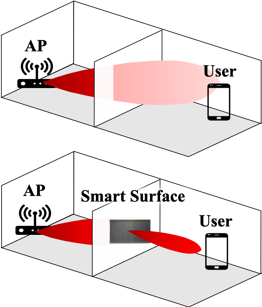
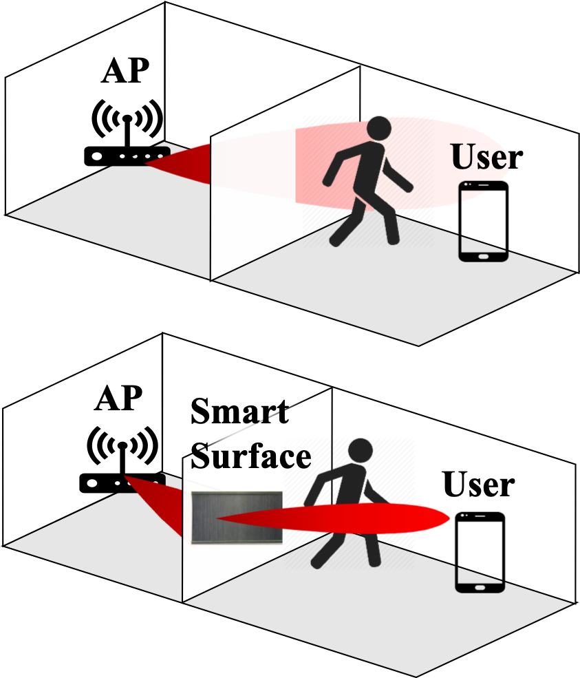
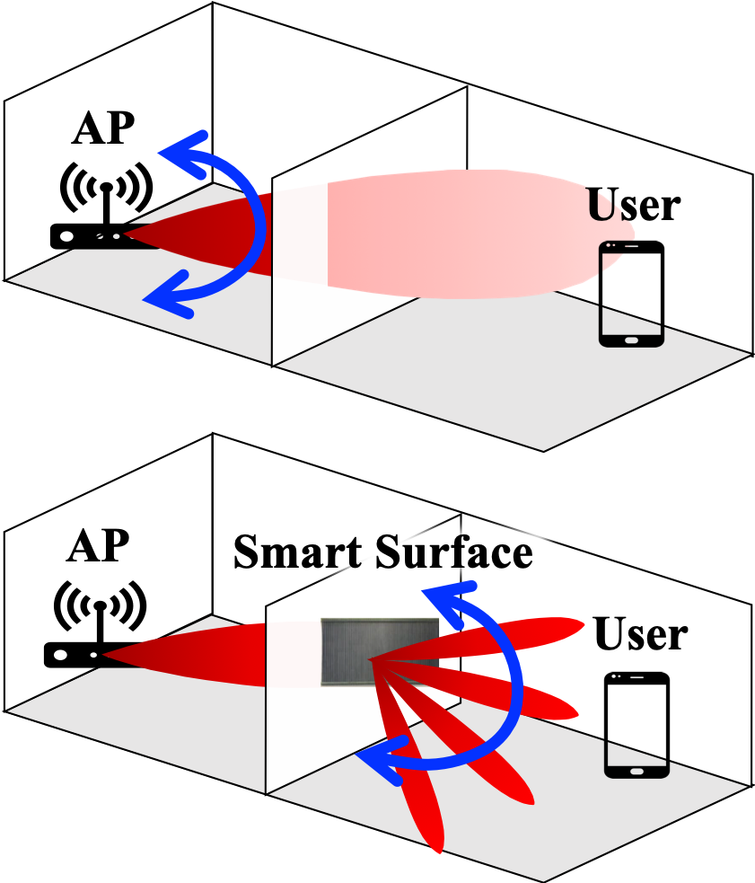
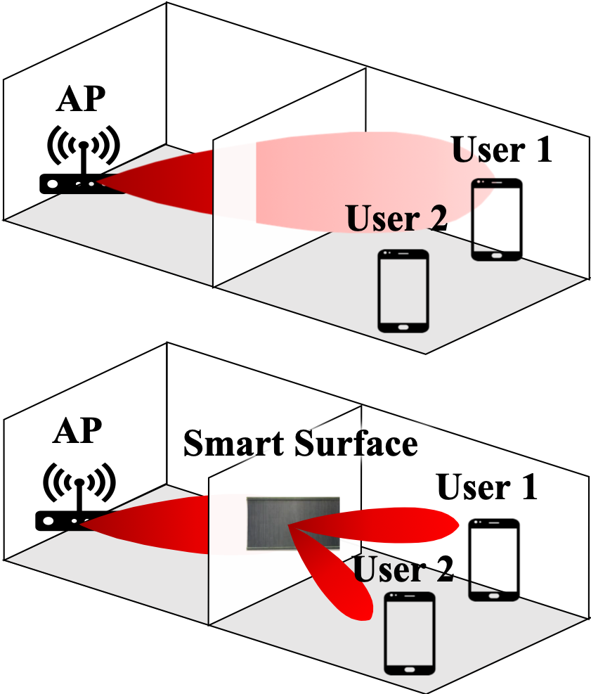
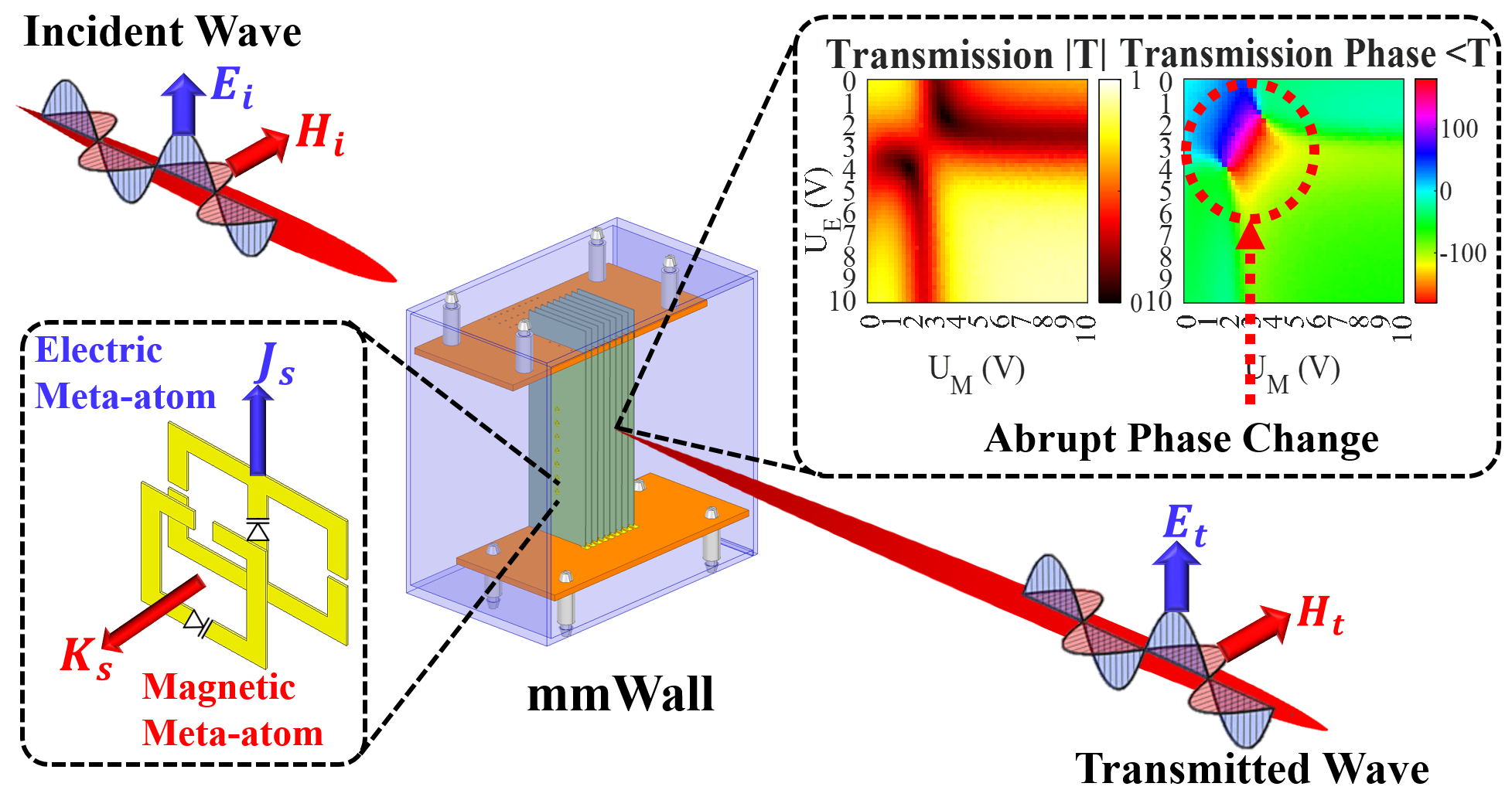
As illustrated in Fig. 1, we can summarize the key advantages of mmWall as follow: (1) mmWall relays and re-focuses the beam at the wall. This way, the beam does not attenuate as it traverses the wall; (2) mmWall provides an alternative path when the direct path is blocked by a human body. (3) Due to a narrow beam, the current solutions for aligning the beams scan the entire space to find the best direction, which incurs a large time delay. By generating the multi-armed beams with different spatial directions and sweeping them concurrently, mmWall enables the fast beam search at the wall; (4) mmWall enables multi-cast by creating and directing one beam per each user; (5) Each element of metasurface, known as a meta-atom, is at least five times smaller than the conventional antenna. mmWall thus has a larger number of elements than the phased array antenna and yields a significant gain enhancement; (6) In general, multiple RF chains are used to generate multiple beams, resulting in a huge power consumption and complex hardware design. In contrast, mmWall doesn’t have a single RF chain and therefore intrinsically consumes low-power.
Roadmap. Section 2 theoretically analyzes Huygens’ metasurface at a finer level. Section 3 introduces a novel approach to scale Huygens’ metasurface to higher mmWave frequency and elaborate how this metasurface relays one or more beams with a full-angle coverage of degrees. In Section 4 we then conduct a preliminary study to prove the efficiency of beam relay and steering performance. Section 5 presents the related works, Section 6 addresses the mobile applications of mmWall, and Section 7 concludes the paper with discussion.
2. Primer: Huygens Metasurfaces
Huygens’ metasurfaces (HMSs) (ding2020metasurface, ; liu2018huygens, ; chen2017reconfigurable, ; zhang2018space, ) comprise a layer of co-located orthogonal electric and magnetic meta-atom, facing each other across dielectric substrate (See metallic rings in Fig. 2). This meta-atom pair introduces a discontinuity in the electromagnetic fields and hence providing the means for manipulation of all attributes of the incident field, including its magnitude and phase. Specifically, as the incident wave () passes through the magnetic meta-atom, the magnetic field of the incident wave induces the rotating current within the metallic loop of the magnetic meta-atom that in turn produces its own magnetic field , which enhance or oppose the incident field. Similarly, the electric meta-atom is excited by the electric field of the incident wave, resulting in the oscillating current loops that creates its own electric response . When these electric and magnetic response of the Huygens’ meta-atom pair interact with the fields of the incident wave, it creates an abrupt phase shift. Hence, by controlling the electric and magnetic responses, Huygens’ metasurface steers the incoming wave to a desired direction. For readers interested in the detailed description refer to (chen2018huygens, ).
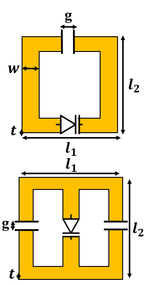
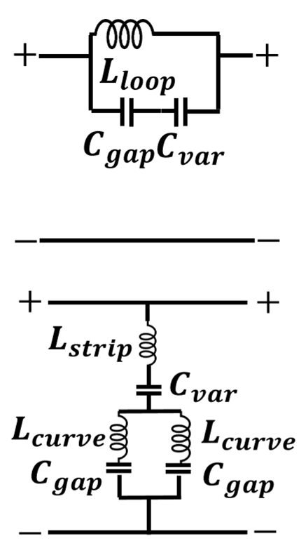
Theoretical Analysis. To induce the magnetic or electric response, the magnetic and electric meta-atom each acts as a resonant circuit, a circuit consisting of an inductor and a capacitor . Figure 3 shows the design parameters of the Huygens’ meta-atoms. The gap of a metallic loop induces a capacitance while the metallic loop itself generates an inductance. Specifically, we can simplify the equation of a gap capacitance as: where is free-space permittivity with the the length of the gap , width of the metallic ring , and metal thickness . The simplified equation of inductance is written as: where is free-space permeability, and and are the dimension of the meta-atom. Since HMS is engineered to oscillate at a resonant frequency , we must modify value to design HMS at a desired frequency. Consider a circuit with one gap capacitor and one inductor (i.e. magnetic meta-atom). We can simplify the expression for the circuit as follow:
| (1) |
where is the speed of light, and is the area of meta-atom, which is equivalent to in Fig. 3(a).
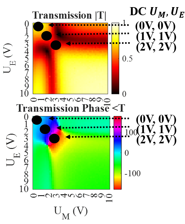
Active HMS. To render HMS reconfigurable, tunable electrical components, such as varactors and p-i-n diodes, are loaded to the meta-atom so that it can tune a metasurface element through voltage bias lines. For mmWall, varactor is used as a voltage-controlled capacitor. As seen in Fig. 3(c), this varactor capacitor forms a series circuit with the gap capacitor . Assuming the equivalent circuit diagram of the magnetic meta-atom, the total capacitance can be written as: . Hence, by applying voltages across varactor, we can slightly shift the resonant frequency from the designed frequency to . Therefore we provide different transmission phases at the targeting frequency . The upper-right graphs in Fig. 2 shows the amplitude of the transmission coefficient and the phase of the transmission coefficient with varying voltage and for the electric and magnetic meta-atoms, respectively. This pattern is called Huygens’ pattern, and it has a full transmission-phase coverage of degrees with a high amplitude.
3. Design
mmWall is a programmable metasurface that operates at mmWave frequency, fully controls the direction of the mmWave beam, and splits the relayed mmWave beam into multiple directions. In this section, we describe our solutions to the challenges in designing the mmWall.
3.1. mmWall meta-atom design
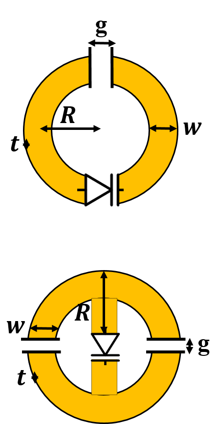
To design mmWall’s meta-atoms to be effective at mmWave frequencies, we need to redesign the meta-atom such that its targeting resonant frequency matches the mmWave frequency at GHz. Given the Eq. 1, we can increase the targeting frequency to GHz by decreasing the area , ring width , and/or increasing the gap size . Accordingly, the simplest, conventional solution is to directly scale down the size of the meta-atom design, such that each and equals , which is a standard meta-atom size. At mmWave, however, a meta-atom with size is too small such that once we load a smallest-available varactor, its packaging completely distorts the tailored electromagnetic surface properties. Hence, we instead reduce the area by changing the rectangular meta-atom into a circular design with the radius . To load varactor, we then fix and to twice the size of varactor (i.e. breaking the convention). New meta-atom design for mmWall is illustrated in Fig. 3(b). With this new meta-atom design, we reduce the area by a factor of , which in turn lowers the inductance and increases the resonant frequency, given the resonant frequency equation. Then, based on theoretical analysis we derived, we fine-tune other geometric parameters until the targeting frequency reaches GHz.
3.2. mmWall relay beam-steering
The conventional phased array antenna calculates the total field pattern by multiplying the element factor, a pattern produced by a single element, to the array factor, a pattern produced by an array of elements. Consider array of identical antennas with spacing and amplitude . The array factor is:
| (2) |
where with as the wavelength of the operating frequency, and is the steering angle. As seen in Eq 2, the phase shift of each element is different. More specifically, the phase of element is larger than the phase of element by , since the path length to element is longer than element. Consequently, to steer the beam towards a particular direction, the phased array antenna must apply different phases for each array element, and the larger the phase difference is, the greater the phased array antenna steers.
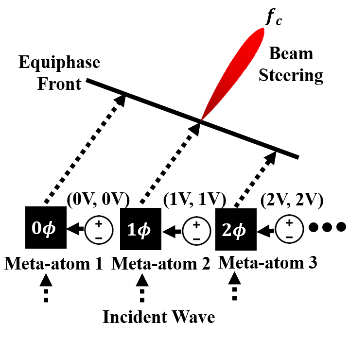
Similarly, mmWall applies a different phase shift at each meta-atom to steer the beam. Specifically, we leverage a full degree transmission-phase coverage of HMS to provide different phase shifts. Let’s assume that we have an array of meta-atom pairs as shown in Fig. 4. For the meta-atom pair, we apply for the magnetic meta-atom and for the electric meta-atom, such that () = (). When we directly map this voltage pair to the Hugyens’ pattern in Fig. 4, the meta-atom pair provides a transmission-phase of with a high transmission-amplitude . For the meta-atom pair, is applied to both meta-atoms, resulting in a different phase shift, , with a high transmission amplitude and so on. At last, we can formulate the array factor as follow:
| (3) |
This equation corresponds to Eq. 2, and therefore we can steer the beam using HMS by varying the voltages. We must note that while the existing relay systems requires two phase antenna arrays, one to receive the incoming signal and another to transmit a new signal with a time delay, our mmWall only need a single array of the meta-atoms as it directly shift the phase of the existing signal.
3.3. mmWall beam splitting and searching
To transform an incoming beam into multi-armed beams, mmWall adopts an additional degree-of-freedom, time, in the control line. In other words, we convolve a high frequency mmWave signal with a low frequency signal and thus achieve a desired Fourier series. More specifically, we add time-modulation in the voltage signal to achieve a time-varying transmission-amplitude |T| and phase <T. When this time-varying transmission signal is periodic, its Fourier transformation becomes harmonics and creates multiple beams with different frequencies, also known as sidebands. Hence, by applying a proper time-varying voltage signal, mmWall can generate the time-varying signal response, in which its Fourier transformation creates a desired number of beams at desired frequencies. Let us define each of time-varying voltage signal and for the electric and magnetic meta-atom as where is the voltage amplitude, is the voltage offset, and is a normalized Fourier series with a modulation frequency , time , and phase . Our goal is to find the solution to the following optimization problem:
| (4) |
where is an optimal set of the voltage waveform coefficients (,,,,). is a mapping function from the voltage waveform to the Huygens’ pattern in Fig. 4, and is a Fourier transformation of the time-varying transmission signal.
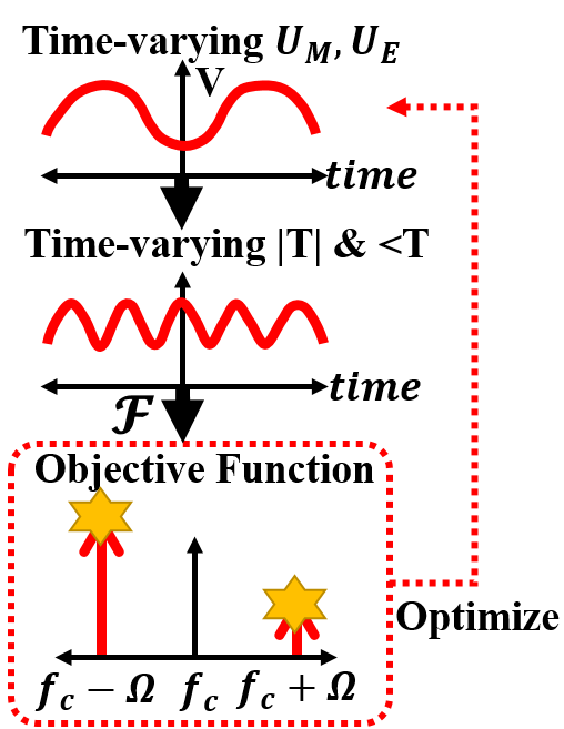
Finally, is the objective function characterizing the scattered power of the desired beams at a desired frequency bin.
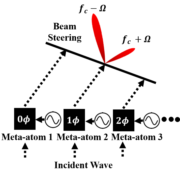
Example. In Fig. 4, we apply a constant DC voltage to each meta-atom, resulting in a constant transmission-amplitude |T| and phase <T that creates a single beam at a carrier frequency . Consider the multi-armed beams scenario in Fig. 5. Its goal is to split the beam into two, one at and another at where is the voltage modulation frequency. Let’s assume that we want to concentrate more energy towards the beam at than the beam at . We can redefine our goal to search for a proper , such that has a large peak at and relatively low peak at . Accordingly, in Fig. 5, our objective function is to maximize the sum of the weighted power at and at , as denoted with the stars. After optimizing with the genetics algorithm, mmWall concurrently steer the multi-armed beams by applying different phase shifts to the optimized voltage waveform of each meta-atom pair, as seen in Fig. 5.
Mirror Mode. mmWall can also reflect the signal back as a mirror. To convert the transmissive mode to the reflective mode, we can simply add degrees phase shift to either or . When the phase of and is identical, the mmWall acts as a "lens" whereas with degree phase difference between and , our mmWall acts as a "mirror".
4. Preliminary Results
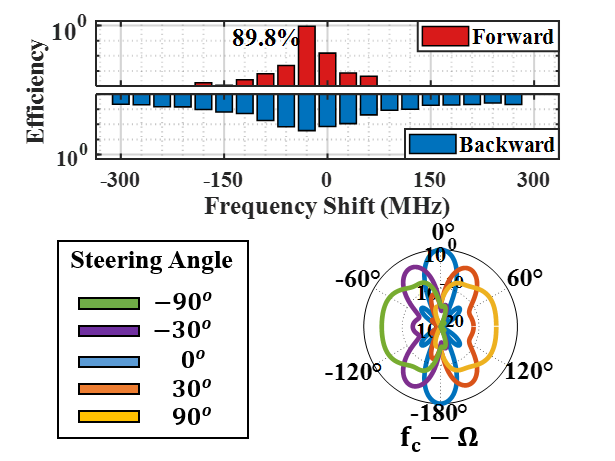
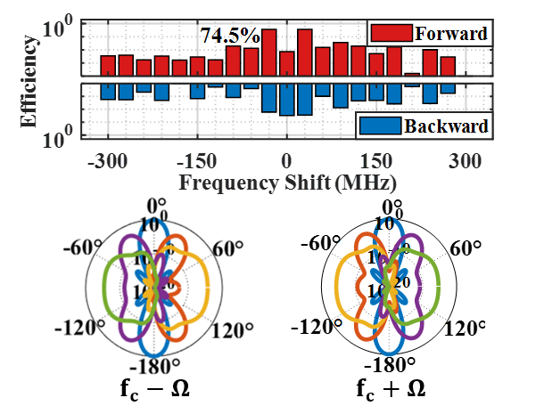
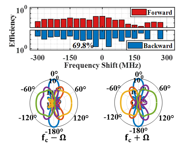
To evaluate mmWall’s ability to relay and steer the mmWave beams, we ran HFSS simulation on our mmWall design with meta-atoms. We also modeled each electric component based on its Simulation Program with Integrated Circuit Emphasis (SPICE) model. We use mmWave signals at GHz and set the voltage modulation frequency to MHz. We evaluate three scenarios: single transmissive beam, two transmissive beams, and two reflective beams. For a single beam, we transform the incident wave at to the signal at whereas for the multi-armed beam scenarios, we translate the incoming beam into two beams, one at and another at .
Beam Efficiency. Figure 6 demonstrates the efficiency of mmWall. For a single transmissive beam (Fig. 6(a)), we observe a single peak at the MHz frequency shift of the forward spectrum. Here, the frequency shift of MHz indicates carrier frequency at GHz, and MHz frequency shift denotes GHz - MHz, which is equivalent to . This peak has efficiency, indicating that nearly of the incident signal is relayed with only dB loss. For the double transmissive beams and double reflective beams, the sum of beam efficiency at and is (approx. dB loss) and (approx. dB loss), accordingly. Furthermore, as we steer the beam away from degree where degree means no phase shift applied across the meta-atoms, the peak power of the beam weakens, slightly. For all three scenarios, there is about dB loss as we steer the beam by or degree. At or degree of the beam-steering angle, there is approximately dB signal loss. We must further note that for the double-beam scenarios, mmWall correctly steers the beam at and another beam at in different directions, simultaneously.
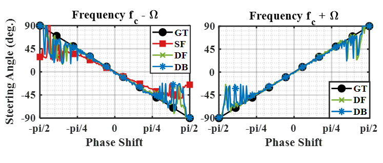
Beam Steering Accuracy. Figure 7 evaluates the beam steering performance of three scenarios as we vary the relative phase value across different meta-atoms. We specifically measure the angle of the peak of the beam. The graph on left shows the steering performance of the beam at for all three scenarios, and the graph on right illustrates steering accuracy of the beam at for the double beam scenarios. The ground-truth values are colored in black with the circle markers. For every scenario, the beam steering angle is highly accurate except for the angle below phase shift and above phase shift. This is because as it steers to a larger angle, the beam may not look symmetric, and thus peak may not be in its center of the beam.
5. Related Work
Smart Surfaces. LAIA (li2019towards, ) helps endpoints by collecting radio energy from one side of the wall, phase-shifting it, and transmitting it to the other side such that the signals arriving in different paths combine constructively. RFocus (arun2020rfocus, ) is a software-controlled surface, made up of thousands of switching elements to focus reflections from a transmitter to a receiver. However, both LAIA and RFocus operate at GHz that has much smaller path loss. Hence, their goal is intrinsically different from ours. First, they don’t address the issue of beam directionality since the beam at GHz is not narrow. Instead, they simply change the phase of the destructively interfering signals to improve overall signal strength. Second, since the effect of blockage is negligible, they don’t consider the human blockage. MoVR (abari2017enabling, ) is a programmable mmWave reflector consists of two directional phased-array antennas. When the LoS signal between the AP and VR headset is blocked by human mobility, the AP steers its beam towards the MoVR, which in turn reflects it towards the headset. However, MoVR only works in a reflective "mirror" mode. In contrast, our mmWall can both relay the beam to another room and/or reflect it back to the same room. Furthermore, unlike mmWall, MoVR cannot generate multiple beams.
Reconfigurable Metasurfaces. Artificially-engineered surfaces, called “meta-surfaces”, have been studied extensively by applied physicists to explore unique electromagnetic properties that do not exist in naturally occurring material. Recent work has proposed metasurfaces that can alter existing signals in the environment itself, such as creating materials with a negative refraction index (smith2004metamaterials, ), engineering complex beam patterns, and manipulating the signal polarization (chen2020pushing, ; wu2019tunable, ). Especially, Huygens’ metasurface (HMS) has gained an attention as a new paradigm for beam refraction, beamforming, and perfect reflection due to its key features: a full transmission-phase coverage of degrees and near-unity transmission. Unlike HMS that manipulates incoming waves in a passive manner, ample works have proposed the active-controlled Huygens’ metasurfaces (chen2017reconfigurable, ; zhang2018space, ; liu2018huygens, ) by loading a tunable electric component like varactors. While these designs have shown a great promise in controlled experiments that quantify performance at a low frequency (approx. to GHz), we cannot directly scale them to higher frequencies due to the conflict between the required meta-atom size and the size of varactor. Furthermore, they have not been integrated into an end-to-end system for wireless communication. In contrast, we present a system that directly improve wireless communication.
6. Mobile Applications
We describe the potential mobile, wireless applications that mmWall can support in real-time and significantly improve.
Virtual and/or Augmented Reality. We have witnessed major advances in virtual reality (VR), augmented reality (AR) and mixed reality (MR) in the gaming and entertainment industry and educational institutions. For instance, VR and AR can not only provide immersive gaming experiences, but also help in guiding the curated objects in a museum with digital versions of artists and enable life-like training simulations to prepare public safety professionals. However, such applications are currently limited in terms of mobility as they require a physical connection via HDMI cable to exchange multiple Gbps of data between a data source (PC or game console) and the headset. For this reason, multiple companies have advocated the use of mmWave links for such applications, which, in turn, experiences a significant difficulty with the presence of obstacles and reflections. Several mmWave relay systems (abari2017enabling, ; tan2018enabling, ) have attempted to solve this link-blockage problem using reconfigurable mmWave reflectors that provide an alternative path when the existing links are blocked. However, these systems only allow mobility within a single room as they can only reflect the signal back. Our mmWall, on the other hand, adaptively establishes a robust mmWave connection through both a reflective and transmissive path across the wall, thus enhancing the ability to move around through live events, with better sense of "presence".
Serverless Computing. Serverless computing is a cloud computing system in which the end users run applications without a traditional server operating system. Instead, the service operators provide and manage machine resources on demand. The most prominent platforms include Amazon Web Service (AWS), Google Cloud, Microsoft Azure, and Cloudflare. In particular, Google Cloud recently launched Game Servers, a managed service that provides gamers a cloud backend for running their games, including multi-player games. Such services open up a plethora of computing opportunities for mobile devices, which are often limited in computational resources. However, the strict latency constraints exist when the operators support real-time services like Game Servers, and these constraints exacerbate when the end users are mobile. With mmWall, we can significantly reduce this latency by continuously supporting multiple Gbps regardless of whether the users walk across the offices or not. Furthermore, mmWall operates on both the downlink and the uplink, which are necessary for such services that require bi-directional communication. Thereby, mmWall can improve the Quality of Service (QoS) for the mobile devices using serverless computing.
Robotic Automation. Robotic automation requires high speed connectivity to stream video to the backend servers in order to accomplish the complex collaborative tasks. In fact, mmWave networks can play a significant role in providing high speed connectivity. However, when it comes to the smart robotic wearhouses and retailors, there are an enormous amount of end-nodes to support. Deploying multiple mmWave AP in every corner and space may allow multiple Gbps connection through LoS paths but with a massive number of mobile robots, it adds additional complexity to the handover process. The use of mmWall not only mitigates complexity in coordinating the communication between the APs and the robots, but also leaves the end-node unchanged. Only the AP and mmWall need to be configured so that mmWall delegates the task of the AP.
7. Discussion
System Design. A high-level idea of our system architecture is as follow: initially, the AP knows the location of mmWall embedded on the wall. If the signal strength of the link between the AP and user is weak, the AP redirects its beam to mmWall. Then, mmWall generates multi-armed beams and concurrently steer them to scan the space and finds the best path to the user (refer to (hassanieh2018fast, ) for beam-alignment using multi-beams). mmWall then reconfigures itself to form one beam with a maximum gain and steers the beam towards the user for data communication. In multi-user scenario, mmWall divides the beam and steer one beam to each user for multi-cast. Bluetooth, GHz, or sub- GHz band can be used to exchange control information between the AP and mmWall and to initially discover the AP at the end user side if the user is not in the same room as the AP. When there are multiple rooms adjacent to a room where the AP is located, we may deploy a single mmWall on each wall between the adjacent rooms.
Uplink Relay. We have previously discussed having metasurface that relays the AP signal to the user on the downlink. However, a single mmWall can act as either a downlink relay or a uplink relay. Said differently, a wave propagating in the reverse direction interacts with the electric and magnetic response induced by mmWall in the same way as a wave propagating in the downlink direction. Thus, by properly applying the phase shifts to the uplink signal, we can steer the incident beam towards the AP.
Implementation Cost. Given that mmWave links require LoS communication, we can assume that every room needs at least two mmWave APs for a full-coverage. With two rooms, the number of the AP scales to four, and with three rooms, the number of the AP scales to six. Since the state-of-the-art Wi-Fi 6 routers cost roughly (netgear, ), the implementation cost reaches approximately for two rooms and for three rooms and so on. Using a smart metasurface, two rooms require only one mmWall and three rooms need two mmWall on the wall between the adjacent rooms. We can breakdown the cost-driving factors of mmWall into the Roger4003C substrate, which costs approximately (spwindustrial, ), and varactor, which costs each (macom, ), Therefore, we can assume that the implementation cost of mmWall is cheaper than deploying multiple mmWave APs.
Power Consumption. Metasurface consumes much less power than conventional array system that leverages patch arrays and phase shifters. It is because metasurface eliminates the need for complicated RF chains, power amplifier, baseband processor, and/or active phase shifters. Said differently, the radiation pattern emitted by mmWall is the superposition of the field transmitted from many meta-atoms, whose amplitude are determined by the tunable resonance response of the meta-atoms and the phase accumulated by their transmitted fields. Since mmWall tunes each meta-atom using simple electric components like varactors (macom, ), it requires minimal additional power for beam steering (POOLE2016519, ). In contrast, many conventional array antennas employ active phase shifters, which consume significant power (shlezinger2020dynamic, ).
8. Conclusion
This paper presents mmWall, a smart surface system that reconfigures itself to relay the beam as a "lens" or "mirror" at the walls, provide abundant path options to remedy mmWave blockage, speed-up the beam alignment process, and to support multiple users, simultaneously. We also present promise for its capability through comprehensive experiments in HFSS simulation. The results demonstrate that mmWall metasurface steers the outgoing beam in a full -degrees, with an single-beam efficiency and double-beam efficiency. We will fabricate this design to build an real smart surface prototype, and focus on refining its system architecture.
9. Acknowledgements
This work is supported by the National Science Foundation under grant CNS-1617161.
References
- [1] O. Abari, D. Bharadia, A. Duffield, and D. Katabi. Enabling high-quality untethered virtual reality. In 14th USENIX Symposium on Networked Systems Design and Implementation (NSDI 17), pages 531–544, 2017.
- [2] V. Arun and H. Balakrishnan. Rfocus: Beamforming using thousands of passive antennas. In 17th USENIX Symposium on Networked Systems Design and Implementation (NSDI 20), pages 1047–1061, 2020.
- [3] K. Chen, Y. Feng, F. Monticone, J. Zhao, B. Zhu, T. Jiang, L. Zhang, Y. Kim, X. Ding, S. Zhang, et al. A reconfigurable active huygens’ metalens. Advanced materials, 29(17):1606422, 2017.
- [4] L. Chen, W. Hu, K. Jamieson, X. Chen, D. Fang, and J. Gummeson. Pushing the physical limits of iot devices with programmable metasurfaces. arXiv preprint arXiv:2007.11503, 2020.
- [5] M. Chen, M. Kim, A. M. Wong, and G. V. Eleftheriades. Huygens’ metasurfaces from microwaves to optics: a review. Nanophotonics, 7(6):1207–1231, 2018.
- [6] X. Ding, Z. Wang, G. Hu, J. Liu, K. Zhang, H. Li, B. Ratni, S. N. Burokur, Q. Wu, J. Tan, et al. Metasurface holographic image projection based on mathematical properties of fourier transform. PhotoniX, 1(1):1–12, 2020.
- [7] H. Hassanieh, O. Abari, M. Rodriguez, M. Abdelghany, D. Katabi, and P. Indyk. Fast millimeter wave beam alignment. In Proceedings of the 2018 Conference of the ACM Special Interest Group on Data Communication, pages 432–445, 2018.
- [8] Z. Li, Y. Xie, L. Shangguan, R. I. Zelaya, J. Gummeson, W. Hu, and K. Jamieson. Towards programming the radio environment with large arrays of inexpensive antennas. In 16th USENIX Symposium on Networked Systems Design and Implementation (NSDI 19), pages 285–300, 2019.
- [9] M. Liu, D. A. Powell, Y. Zarate, and I. V. Shadrivov. Huygens’ metadevices for parametric waves. Physical Review X, 8(3):031077, 2018.
- [10] MACOM. Macom technology solutions, solderable gaas constant gamma flip-chip varactor diode , mavr-000120-1411. https://www.macom.com/products/product-detail/MAVR-000120-14110P.
- [11] Netgear. Nighthawk ax12 wifi 6 router - rax120 12-stream router. https://www.netgear.com/home/wifi/routers/rax120.
- [12] C. Poole and I. Darwazeh. Chapter 15 - microwave oscillator design. In C. Poole and I. Darwazeh, editors, Microwave Active Circuit Analysis and Design, pages 519 – 558. Academic Press, Oxford, 2016.
- [13] N. Shlezinger, G. C. Alexandropoulos, M. F. Imani, Y. C. Eldar, and D. R. Smith. Dynamic metasurface antennas for 6g extreme massive mimo communications. arXiv preprint arXiv:2006.07838, 2020.
- [14] D. R. Smith, J. B. Pendry, and M. C. Wiltshire. Metamaterials and negative refractive index. Science, 305(5685):788–792, 2004.
- [15] spwindustrial. Rogers h.frequency laminates r4003c , 18" x 24" .032" thick, 1/1 oz cu. https://spwindustrial.com/rogers-h-frequency-laminates-r4003c-18-x-24-032-thick-1-1-oz-cu/.
- [16] X. Tan, Z. Sun, D. Koutsonikolas, and J. M. Jornet. Enabling indoor mobile millimeter-wave networks based on smart reflect-arrays. In IEEE INFOCOM 2018-IEEE Conference on Computer Communications, pages 270–278. IEEE, 2018.
- [17] Z. Wu, Y. Ra’di, and A. Grbic. Tunable metasurfaces: A polarization rotator design. Physical Review X, 9(1):011036, 2019.
- [18] L. Zhang, X. Q. Chen, S. Liu, Q. Zhang, J. Zhao, J. Y. Dai, G. D. Bai, X. Wan, Q. Cheng, G. Castaldi, et al. Space-time-coding digital metasurfaces. Nature communications, 9(1):1–11, 2018.