Néel domain wall as a tunable filter for optically excited magnetostatic waves
Abstract
We present a concept of a tunable optical excitation of spin waves and filtering their spectra in a ferromagnetic film with 180∘ Néel domain wall. We show by means of micromagnetic simulation that the fluence of the femtosecond laser pulse and its position with respect to the domain wall affect the frequencies of the excited spin waves, and the presence of the domain wall plays crucial role in control of the spin waves’ spectrum. The predicted effects are understood by analyzing the changes of the spin waves’ dispersion under the impact of the laser pulse.
I Introduction
In magnonics, spin waves (SW) are used to implement alternative methods of transferring information in magnetic nanostructures that can replace traditional transistor circuits [1, 2, 3, 4]. Unlike electric charges, SW can propagate in materials even without free charge carriers [5, 6]. Thus, SW propagation is not associated with Joule losses which reduction is the challenging problem in traditional electronics. Different types of magnetic ordering support SW with frequencies in the range from GHz to THz [7, 8, 9, 10], extending the operation rates of magnonics circuits.
Developing approaches for controlling SW is essential for bringing magnonics concepts to applications. Control of SW amplitude, phase, velocity, and propagation direction have been demonstrated by introducing various types of magnetic non-uniformity in the SW guiding media [11, 12, 13, 14]. Particularly, topological defects such as domain walls (DW) and skyrmions change amplitude and phase of SW passing through them [15, 16, 17, 18, 19, 20, 21, 22, 23, 24, 25]. In parallel, tunable magnetic non-uniformities, e.g., those induced by illuminating a magnetic structure with light, are of particular interest since they allow creating reconfigurable magnonic elements [26, 27, 28, 29]. Furthermore, changing magnetic properties of a medium locally by femtosecond laser pulses appears to be one of the efficient ways to generate propagating spin waves and to tune their characteristics [14, 30, 31, 32, 33, 34].
There is a broad range of mechanisms enabling manipulation of magnetic ordering by laser pulses [35, 36, 37], including ultrafast demagnetization, inverse magneto-optical effects, excitation of coherent phonons, ultrafast change of magnetic anisotropy. The last one is a versatile mechanism as the anisotropy could be of different nature: magnetocrystalline, shape-, strain-induced, etc. Furthermore, laser-induced anisotropy changes as a triggering mechanism of magnetization dynamics can be realized in metals, semiconductors, and dielectrics [38] through ultrafast heating [39, 40, 41], excitation of lattice distortions [42], photomagnetic effects [43], etc. Therefore, it is appealing to realize a tunable source of SW by combining the advantages of ultrafast laser-induced excitation of SW with their control by local magnetic defects, such as DW.
In this Article, we present a micromagnetic study of magnetostatic spin waves (MSW) optically excited in the vicinity of a 180∘ Néel DW in a thin ferromagnetic film. MSW are triggered by changes of the magnetic anisotropy of the film resulting from ultrafast laser-induced increase of the lattice temperature occurring within a few picoseconds after the excitation [39, 40, 41]. We show that the laser-excited area and the DW effectively form a tunable source of MSW. Excitation of selected frequencies in the MSW spectrum is found to be controlled by the laser spot - DW distance, as well as by laser pulse fluence and laser spot width.
II Model details
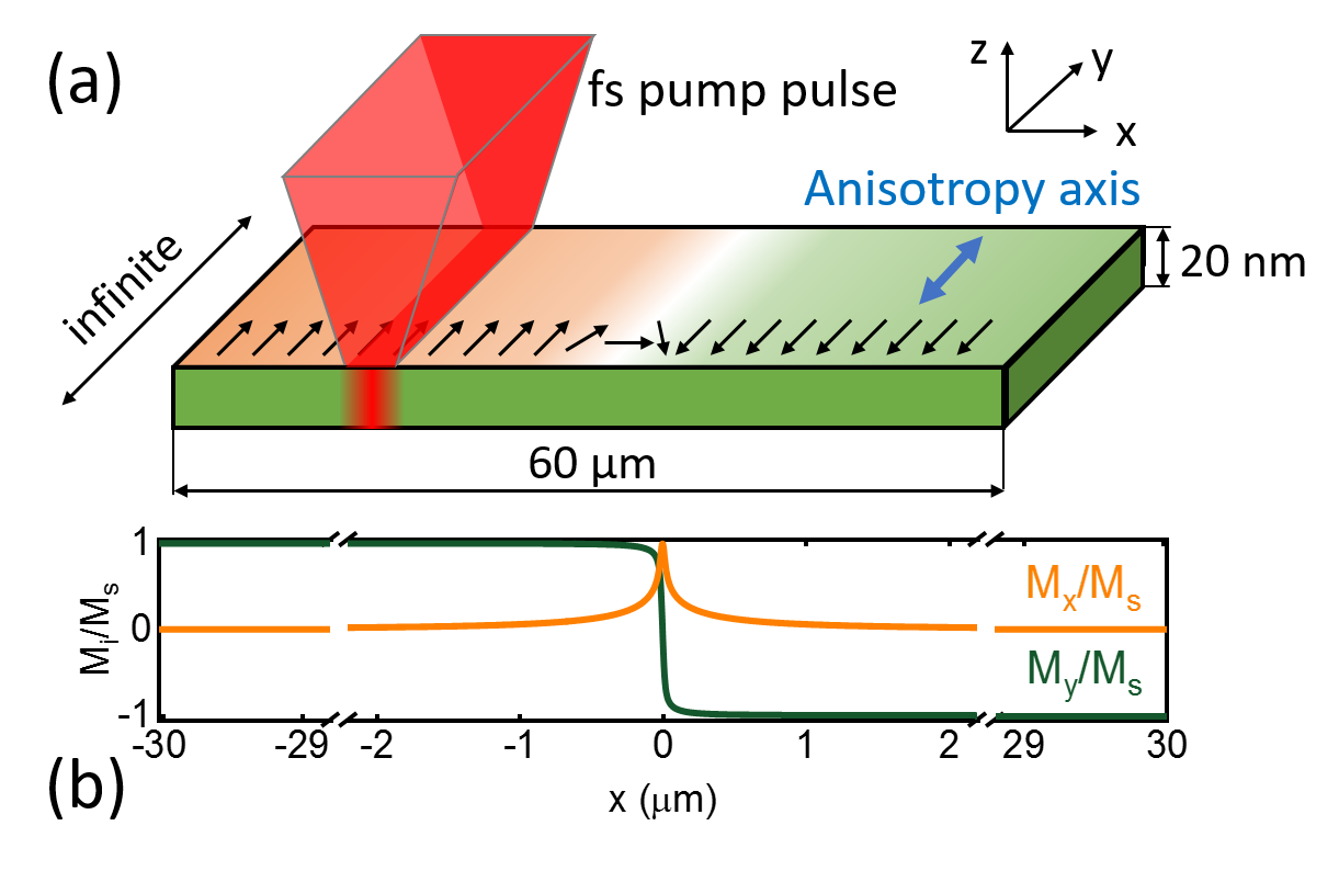
We use micromagnetic numerical calculations on a model system of a ferromagnetic strip. The material parameters of the strip are: the saturation magnetization = 800 kA/m, exchange stiffness = 1.310-11 J/m, Gilbert damping constant =0.008, uniaxial anisotropy parameter = 5 kJ/m3. The strip has a width of 60 m in the -direction, infinite length in the -direction, and a thickness of 20 nm, as shown in Fig.1(a). Easy axis of magnetic anisotropy is along the -axis.
The Object Oriented MicroMagnetic Framework OOMMF [44] is utilized for solving the Landau–Lifshitz–Gilbert equation [45, 46]:
| (1) |
where is magnetization, is time, is the Gilbert gyromagnetic ratio, is the effective field consisting of anisotropy, exchange and magnetostatic fields. We consider the case when no external magnetic field is applied. The solution of Eq. (1) is the dynamics of as a function of following the excitation with the laser pulse. We use a time step of 100 fs and a total time window of 4 ns. A cell size of nm3 is chosen to be smaller than both the magnetostatic exchange length and the magnetocrystalline exchange length [47]. The infinite strip length along the -axis is modeled with 1D periodic boundary conditions. The calculated initial distribution of is a two-domain state with the 180∘ Néel DW at the center of the strip, ; is oriented in the film plane (Fig.1(b)).
We assume the impact of the optical laser pulse as a local relative reduction of the anisotropy parameter resulting from the laser-induced heating. As found in various experiments, reduction of the anisotropy parameter occurs at a picosecond time scale [40, 39], and, thus, can be approximated in our model by the instantaneous decrease of . Following recovery of to its equilibrium value occurs at time scales of the order of a few nanoseconds, and is neglected in our model.
We consider the pump spot having Gaussian profile along -axis and elongated infinitely along -axis to model the excitation of plane SW, similar to recent all-optical experiments [48, 14, 49]. The resulting spatial-temporal profile of the anisotropy change is
| (2) |
where is the position of the pump spot center, is a Heaviside function, characterizes the width of the pump. In the following, we refer to as the pump width. It is worth noting that the minimum accessible value of is limited by the diffraction limit and is of a few hundreds of nanometers. Thus, the range of wavenumbers for optically excited SW propagating laterally has the upper limit of [50, 32]. Thus, wavenumbers lesser than 10 rad/m are exited in optical experiments, what corresponds to the magnetostatic type of SW. Nonetheless, exchange perpendicular standing SW are accessible by optical excitation in flat metal films [51, 52] and complex dielectric structures [53]. Such waves do not propagate laterally and are omitted from the consideration below.
The analysis of MSW properties is based on monitoring the temporal and spatial evolution of the out-of-plane component of the magnetization as laser-induced MSW are usually detected in all-optical pump-probe experiments using polar magneto-optical Kerr effect in reflection [33, 32, 51, 50] or Faraday effect in transmission [30, 14, 48, 31, 49]. Similar to all optical pump-probe experiments, we assume the detection of at a variable position .
III Results and discussion
III.1 Excitation of spin waves
Figure 2(a) shows the spatial-temporal distribution of for the pump pulse positioned at m. The calculations show the propagation of MSW packets from the pump spot in both directions along the -axis.
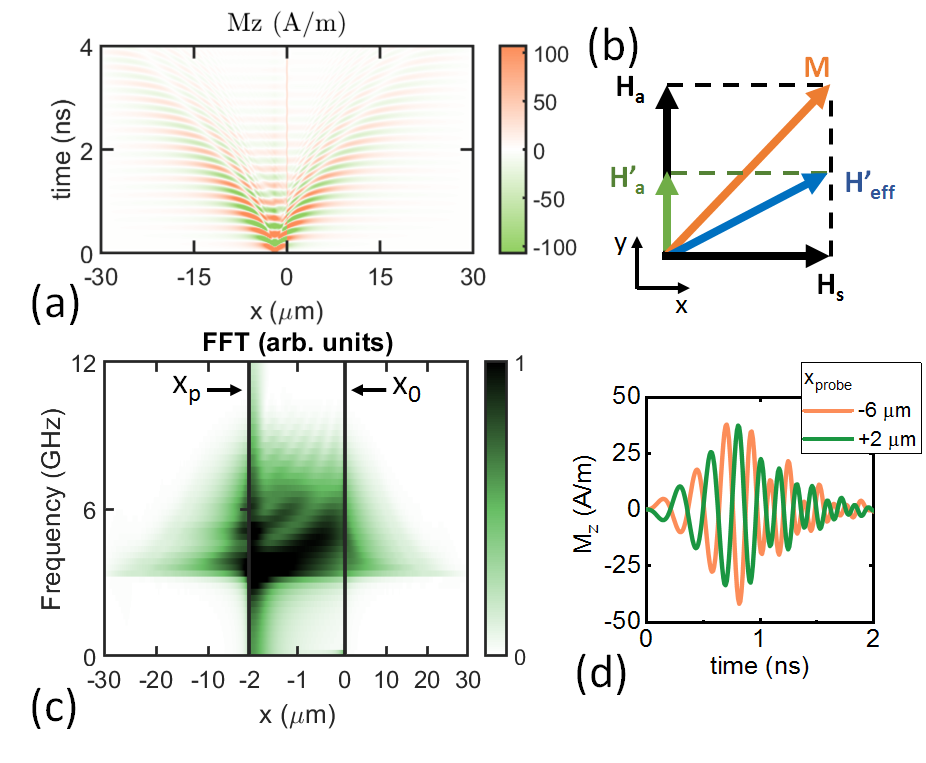
The excitation of MSW is enabled by an abrupt reorientation of effective field caused by the pump, as shown schematically in Fig.2(b). At equilibrium, is a sum of stray field and anisotropy field , where , is the unit vector along the -axis. Non-zero component of along -axis is proportional to . Stray field appears because of the presence of the DW and decreases with the distance from the wall (Fig.1(b)). As decreases due to laser-induced change of the anisotropy parameter , changes its magnitude and orientation to at the time scale much shorter than the magnetization precession period. This leads to a non-zero angle between and in the -plane at with corresponding non-zero torque acting on :
| (3) |
where is the unit vector along the -axis. Non-zero T triggers the precession of M within the pump spot, which in turn launches the propagation of MSW outside the spot.
Equation (III.1) shows that the described mechanism of MSW excitation requires presence of the DW. Indeed, the absence of DW means the initial single domain state of the film with and aligned along axis and resulting at any . Thus, the change of alters , but does not affect the direction of . The presence of DW in the two-domain state provides non-zero (Fig.1(b)) with the corresponding non-zero -component of in the vicinity of . Therefore, the presence of DW in our system enables MSW excitation via ultrafast changes of magnetic anisotropy even in zero applied magnetic field.
III.2 Spectrum of MSW optically excited in the DW vicinity
Here we turn to the analysis of the MSW features related to the DW presence. The spatial-temporal maps show the reflection and transmission of the MSW from/through DW (Fig.2(a)). For detailed movie of the MSW propagation see Suppl. Mat. [54]. The reflection is due to nonuniform in the DW vicinity. Indeed, the orientation of defines the MSW dispersion law [55], where and are MSW frequency and wavenumber, respectively. Far from DW, and are orthogonal and corresponds to the surface mode of MSW [56]. In the DW vicinity, acquires a projection on the -axis resulting in corresponding changes of . Thus, the DW works as a non-uniformity of the effective refractive index for MSW, and, as a consequence, a fraction of MSW packet is reflected from DW [17]. The reflected MSW interferes with the MSW propagating directly from the pump spot at . We note that the DW displacement resulting from the interaction with the MSW wavepacket is found to be of 4 nm only (1 cell of the mesh) and, thus is omitted from the consideration below.
To analyze in detail the MSW interference at various , we performed one-dimensional fast Fourier transform (1D FFT) of the temporal signals at different . The resulting - maps (Fig.2(c)) demonstrate an evolution of MSW packet’s spectrum with , possessing a fir-tree-shape. In particular, there are multiple peaks in the FFT spectra at due to the interference. The range does not reveal any pronounced interference pattern, and the MSW spectrum possesses a single broad maximum. Thus, below, we focus our discussion on the properties of MSW at . However, we note that DW brings the phase shift of to the MSW packet at (Fig.2(d)). The effect could be described as a switch of a spin angular momentum of magnons passing through the DW and was observed in resent experiments [24].
At , we distinguish two ranges, and , with different interference patterns and multipeak spectra. The region can be seen as a resonator formed by DW and the area excited with the pump pulse. Here DW works as a partially reflecting mirror for MSW, as described above, and the pump spot produces non-uniformity of and, thus, acts as a second mirror of the resonator. Indeed, the changes of modify with corresponding variation of inside the pump spot. As a result the spot works as a potential gap for some MSW frequencies, as discussed below in Sec. D. Detailed discussion about the traps of MSW induced by continuous wave lasers could be found elsewhere [57, 58].
In the region , MSW exit the DW-pump resonator and possess spectrum with equidistant peaks. As we show below, the properties of the resonator are defined by the pump parameters, and it enables controllable variations of MSW spectra. Below, we focus on discussion of the region as the frequency composition of MSW packet does not varies with here.
III.3 Effect of the pump position on the MSW spectrum
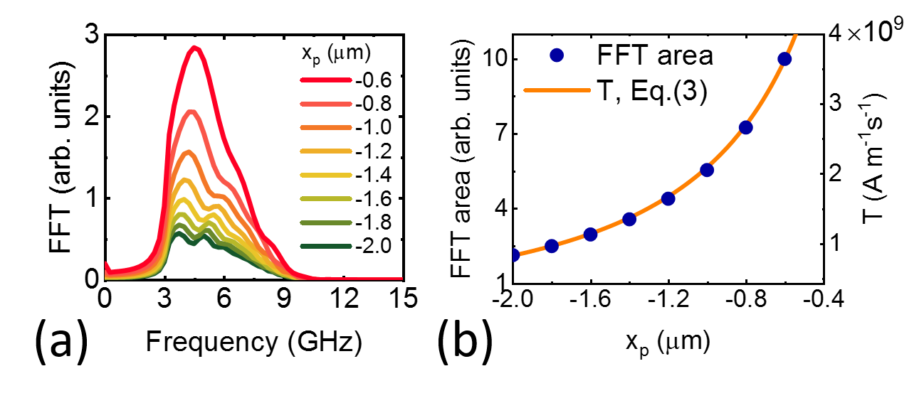
Figure 3(a) shows spectra of the MSW obtained at m for different positions of the pump spot . As can be seen, the variation of affects the shape and amplitude of MSW spectrum at . This is a result of the changes of the DW-pump resonator length , on the one hand, and the spatial variation of in the DW vicinity, on the other hand.
The pump position defines , that, in turn, affects the resonance peaks in the spectrum of MSW and their spectral positions. The number of peaks is also defined by . In particular, for larger more peaks with smaller distance between them occur within the MSW spectrum (Fig.3(a)). Additionally, the choice of defines the amplitude of the excited MSW as follows. defines the value of and inside the pump spot. They are maximal in the DW vicinity, leading to a maximal laser-induced torque (Eq. (III.1)) near the DW. Thus, for smaller , larger amplitude of MSW is observed. To demonstrate it, we find the amplitude of the spectrally broad MSW packet as the area under the FFT curve and plot it as a function of in Fig. 3(b). As can be seen, the change of the MSW packet amplitude with follows the dependence from Eq.(III.1).
III.4 Effect of pump fluence and width on the MSW spectrum
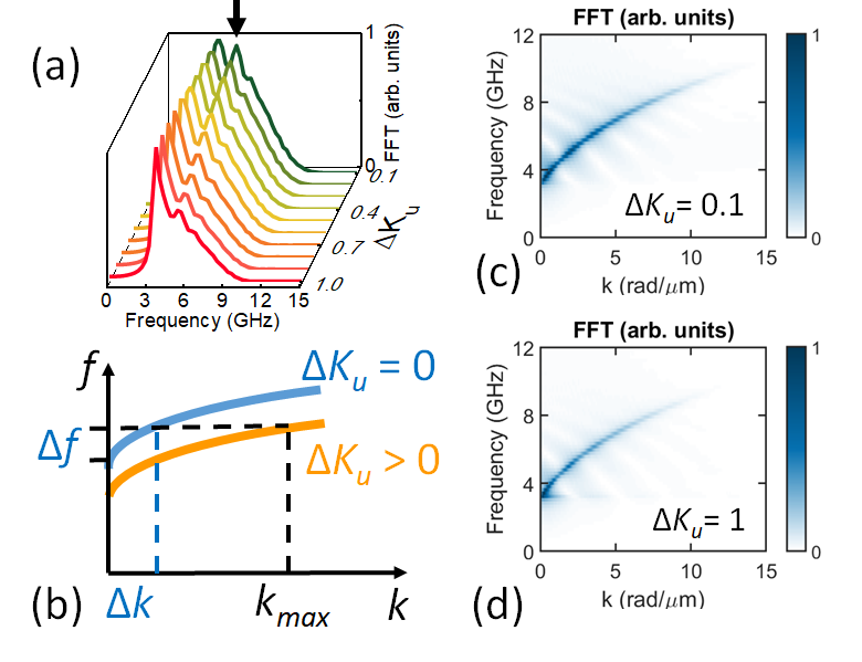
To simulate the effect of the optical pump fluence variation on the MSW properties, we performed calculations for different values of at constant . As a result, the change of leads to the change of MSW spectrum. Particularly, the increase of narrows the spectrum width and decreases the relative amplitude of high-frequency resonance peaks (Fig.4(a)).
The effect of pump fluence on MSW spectra could be described qualitatively in terms of shift due to (Fig.4(b)). The spectrum of the excited MSW packet is limited by two factors – the time scale of decrease, and the range of excited MSW wavenumbers . Typical is within a few hundreds of fs in the experiments, and is within the THz range, which is substantially larger than MSW frequency in ferromagnets. The maximum value of excited MSW wavenumbers is defined by the width of the spatial Fourier transform of the pump spot [30, 32, 50]. Thus, the spectral range of the excited MSW spans from to (Fig.4(b)). The decrease of leads to a negative frequency shift of inside the pump spot due to decrease of (lower curve in Fig.4(b)). Thus, a smaller spectral width of the MSW is observed outside the laser spot as there is a cut-on frequency (upper curve in Fig.4(b)). The increase of leads to the smaller range of for MSW propagating outside the spot.
The effect of the MSW spectrum narrowing is seen in the calculation results (Fig.4(a)). Notably, the ratio between the amplitudes of resonance peaks changes with . The increase of leads to narrowing of the range of the MSW wavenumbers detected outside of the pump spot, as follows from the scheme (Fig.4(b)) and verified by reconstruction of from the calculated - maps with the 2D FFT (Fig.4(c,d)).
The dispersion scheme (Fig.4(b)) explains also the spatial decay of the low-frequency part of the MSW spectrum evident in Fig.2(c). Outside of the pump spot, only the high-frequency part of MSW packet can propagate as the lower frequencies are forbidden at (upper curve in Fig.4(b)). As a result, the magnetization precession with is observed only within the laser-excited spot, which is seen as a ”trunk” of the ”tree” at on the - map (Fig.2(c)). The shape of ”coma” is related to the stronger spatial decay of the high frequency part of the MSW packet upon propagation. Indeed, the propagation length of the MSW with certain is determined by its lifetime and phase velocity as
| (4) |
Thus, the positive slope of leads to faster spatial decay of MSW with higher .
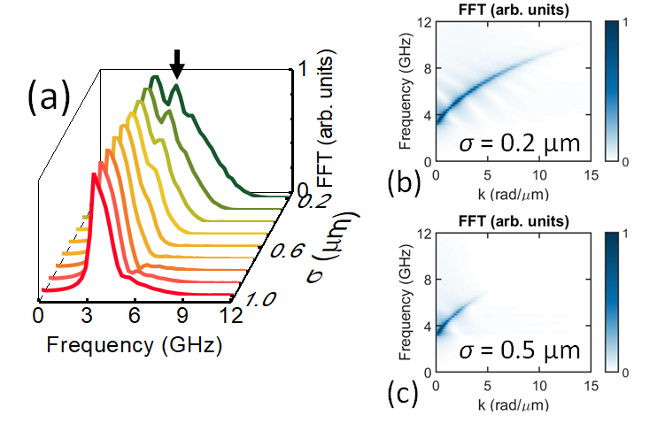
The increase of the pump spot width at constant leads to narrowing of MSW spectra, as demonstrated in Fig.5(a). The effect is a result of the decrease of the maximal wavevector if MSW excited at larger . Therefore, in this case, the spectrum of exited MSW appears to be narrower with the suppressed high-frequency part (Fig.4(b)). The effect of the spectra narrowing is clearly seen in the reconstructed dispersions of MSW (Fig.5(b,c)). Notably, for small values of there are additional resonance peaks appearing in the MSW spectra caused by DW-pump resonator.
IV Conclusions
We have shown the number of features of MSW optically excited by a femtosecond laser pulse in the vicinity of DW in the thin strip of a ferromagnet. Firstly, the presence of DW makes it possible to excite MSW via the change of magnetic anisotropy induced by ultrafast laser heating in zero applied magnetic field, as the internal magnetic field of the stripe is non-uniform. This contrasts with the case of the single domain state, when the excitation of MSW via such anisotropy change requires an applied magnetic field. Secondly, focused optical pulse produces local changes in magnetic properties and, therefore, DW-pump spot system forms the resonator for MSW. As a result of the interference of MSW propagating from the pump spot and reflected by the DW, the spectrum of the MSW packet outside the resonator possesses a complex structure with several resonance peaks. The properties of the resonator depend on the pump parameters and position, enabling the adjustment of MSW spectrum. For instance, the pump position allows tuning the frequencies and amplitudes of the peaks in the spectrum of MSW packets. The increase of laser pulse fluence leads to the narrowing of MSW spectrum and the change of the ratio between the amplitudes of the resonance peaks in the spectrum. Such tuning of the MSW packet is not available in traditional RF methods of SW excitation as a RF field does not vary the magnetic properties of SW guiding media. Moreover, as the time scale of the anisotropy change with fs-laser pulses is of about 1 ps, the presented SW resonator could be realized as an element of ultrafast optically reconfigurable magnonics [26, 27].
Finally, we note that the laser-induced anisotropy changes can also have different origins apart from ultrafast heating. Thus, there are no principal restrictions on the sign and value of , as well as on its temporal evolution. Furthermore, the presented concept of MSW excitation and spectrum modification is expected to work near any magnetic non-uniformity inducing spatially varying stray and/or demagnetizing fields. Such a non-uniformity can be induced by Néel or Bloch DW, magnetic skyrmion, bubble domain, impurities, etc. Each type of non-uniformity presents an individual interest for the study as the internal structure, size, and topology affect its interaction with SW drastically [17, 25]. Importantly, the position and internal structure of magnetic non-uniformities, DW in particular, can be controlled by external magnetic and electric [59] fields, spin-polarized currents [60], and even by propagating SW [20, 17, 21, 22, 23], opening additional paths to tune the SW properties in magnonic devices.
Author statement
N.E. Khokhlov: Methodology, Software, Writing - Review & Editing, Supervision A.E. Khramova: Conceptualization, Writing - Original Draft Ia.A. Filatov: Formal analysis P.I. Gerevenkov: Software, Visualization B.A. Klinskaya: Visualization A.M. Kalashnikova: Conceptualization, Writing - Review & Editing
acknowledgments
The authors thank V.I. Belotelov for fruitful discussions. N.E.Kh. and A.E.Kh. acknowledge financial support by the Russian Foundation for Basic Research (project No. 19-32-50128) and the ”BASIS” Foundation (grants No. 19-1-3-42-1 and 18-2-6-202-1).
Competing interests
The authors declare no competing interests.
References
- Lenk et al. [2011] B. Lenk, H. Ulrichs, F. Garbs, and M. Mnzenberg, The building blocks of magnonics, Physics Reports 507, 107 (2011).
- Nikitov et al. [2015] S. A. Nikitov, D. V. Kalyabin, I. V. Lisenkov, A. N. Slavin, Y. N. Barabanenkov, S. A. Osokin, A. V. Sadovnikov, E. N. Beginin, M. A. Morozova, Y. P. Sharaevsky, Y. A. Filimonov, Y. V. Khivintsev, S. L. Vysotsky, V. K. Sakharov, and E. S. Pavlov, Magnonics: a new research area in spintronics and spin wave electronics, Phys. Usp. 58, 1002 (2015).
- Chumak et al. [2015] A. V. Chumak, V. I. Vasyuchka, A. A. Serga, and B. Hillebrands, Magnon spintronics, Nature Physics 11, 453 (2015).
- Mahmoud et al. [2020] A. Mahmoud, F. Ciubotaru, F. Vanderveken, A. V. Chumak, S. Hamdioui, C. Adelmann, and S. Cotofana, Introduction to spin wave computing, Journal of Applied Physics 128, 161101 (2020).
- Kajiwara et al. [2010] Y. Kajiwara, K. Harii, S. Takahashi, J. Ohe, K. Uchida, M. Mizuguchi, H. Umezawa, H. Kawai, K. Ando, K. Takanashi, S. Maekawa, and E. Saitoh, Transmission of electrical signals by spin-wave interconversion in a magnetic insulator, Nature 464, 262 (2010).
- Hou et al. [2019] D. Hou, Z. Qiu, and E. Saitoh, Spin transport in antiferromagnetic insulators: progress and challenges, NPG Asia Mater 11, 35 (2019).
- Wang et al. [2002] Z. Wang, M. Kuok, S. Ng, D. Lockwood, M. Cottam, K. Nielsch, R. Wehrspohn, and U. Gösele, Spin-wave quantization in ferromagnetic nickel nanowires, Physical review letters 89, 027201 (2002).
- Cramer et al. [2017] J. Cramer, E.-J. Guo, S. Geprägs, A. Kehlberger, Y. P. Ivanov, K. Ganzhorn, F. Della Coletta, M. Althammer, H. Huebl, R. Gross, J. Kosel, M. Kläui, and S. T. B. Goennenwein, Magnon Mode Selective Spin Transport in Compensated Ferrimagnets, Nano Lett. 17, 3334 (2017).
- Rezende et al. [2019] S. M. Rezende, A. Azevedo, and R. L. Rodríguez-Suárez, Introduction to antiferromagnetic magnons, Journal of Applied Physics 126, 151101 (2019).
- Lebrun et al. [2020] R. Lebrun, A. Ross, O. Gomonay, V. Baltz, U. Ebels, A.-L. Barra, A. Qaiumzadeh, A. Brataas, J. Sinova, and M. Kläui, Long-distance spin-transport across the Morin phase transition up to room temperature in ultra-low damping single crystals of the antiferromagnet -, Nat Commun 11, 6332 (2020).
- Vasiliev et al. [2007] S. Vasiliev, V. Kruglyak, M. Sokolovskii, and A. Kuchko, Spin wave interferometer employing a local nonuniformity of the effective magnetic field, Journal of Applied Physics 101, 113919 (2007).
- Sadovnikov et al. [2015] A. V. Sadovnikov, C. S. Davies, S. V. Grishin, V. V. Kruglyak, D. V. Romanenko, Y. P. Sharaevskii, and S. A. Nikitov, Magnonic beam splitter: The building block of parallel magnonic circuitry, Appl. Phys. Lett. 106, 192406 (2015).
- Stigloher et al. [2016] J. Stigloher, M. Decker, H. S. Körner, K. Tanabe, T. Moriyama, T. Taniguchi, H. Hata, M. Madami, G. Gubbiotti, K. Kobayashi, T. Ono, and C. H. Back, Snell’s law for spin waves, Phys. Rev. Lett. 117, 037204 (2016).
- Hioki et al. [2020a] T. Hioki, Y. Hashimoto, and E. Saitoh, Bi-reflection of spin waves, Commun Phys 3, 188 (2020a).
- Hertel et al. [2004] R. Hertel, W. Wulfhekel, and J. Kirschner, Domain-wall induced phase shifts in spin waves, Phys. Rev. Lett. 93, 257202 (2004).
- Buijnsters et al. [2016] F. J. Buijnsters, Y. Ferreiros, A. Fasolino, and M. I. Katsnelson, Chirality-dependent transmission of spin waves through domain walls, Phys. Rev. Lett. 116, 147204 (2016).
- Chang et al. [2018] L.-J. Chang, Y.-F. Liu, M.-Y. Kao, L.-Z. Tsai, J.-Z. Liang, and S.-F. Lee, Ferromagnetic domain walls as spin wave filters and the interplay between domain walls and spin waves, Scientific reports 8, 1 (2018).
- Albisetti et al. [2020] E. Albisetti et al., Synthetic Antiferromagnets: Optically Inspired Nanomagnonics with Nonreciprocal Spin Waves in Synthetic Antiferromagnets, Advanced Materials 32, 2070063 (2020).
- Hämäläinen et al. [2018] S. J. Hämäläinen, M. Madami, H. Qin, G. Gubbiotti, and S. van Dijken, Control of spin-wave transmission by a programmable domain wall, Nat Commun 9, 4853 (2018).
- Han et al. [2009] D.-S. Han, S.-K. Kim, J.-Y. Lee, S. J. Hermsdoerfer, H. Schultheiss, B. Leven, and B. Hillebrands, Magnetic domain-wall motion by propagating spin waves, Appl. Phys. Lett. 94, 112502 (2009).
- Dadoenkova et al. [2019] N. N. Dadoenkova, Y. S. Dadoenkova, I. L. Lyubchanskii, M. Krawczyk, and K. Y. Guslienko, Inelastic Spin‐Wave Scattering by Bloch Domain Wall Flexure Oscillations, Phys. Status Solidi RRL 13, 1800589 (2019).
- Yan et al. [2011] P. Yan, X. S. Wang, and X. R. Wang, All-magnonic spin-transfer torque and domain wall propagation, Phys. Rev. Lett. 107, 177207 (2011).
- Wang et al. [2012] X.-g. Wang, G.-h. Guo, Y.-z. Nie, G.-f. Zhang, and Z.-x. Li, Domain wall motion induced by the magnonic spin current, Phys. Rev. B 86, 054445 (2012).
- Han et al. [2019] J. Han, P. Zhang, J. T. Hou, S. A. Siddiqui, and L. Liu, Mutual control of coherent spin waves and magnetic domain walls in a magnonic device, Science 366, 1121 (2019).
- Lan and Xiao [2021] J. Lan and J. Xiao, Skew scattering and side jump of spin wave across magnetic texture, Phys. Rev. B 103, 054428 (2021).
- Vogel et al. [2015] M. Vogel, A. V. Chumak, E. H. Waller, T. Langner, V. I. Vasyuchka, B. Hillebrands, and G. von Freymann, Optically-reconfigurable magnetic materials, Nature Physics 11, 487 (2015).
- Grundler [2015] D. Grundler, Reconfigurable magnonics heats up, Nature Physics 11, 438 (2015).
- Vogel et al. [2018] M. Vogel, R. Aßmann, P. Pirro, A. V. Chumak, B. Hillebrands, and G. von Freymann, Control of spin-wave propagation using magnetisation gradients, Scientific Reports 8, 11099 (2018).
- Sadovnikov et al. [2019] A. V. Sadovnikov, E. N. Beginin, S. E. Sheshukova, Y. P. Sharaevskii, A. I. Stognij, N. N. Novitski, V. K. Sakharov, Y. V. Khivintsev, and S. A. Nikitov, Route toward semiconductor magnonics: Light-induced spin-wave nonreciprocity in a structure, Phys. Rev. B 99, 054424 (2019).
- Satoh et al. [2012] T. Satoh, Y. Terui, R. Moriya, B. A. Ivanov, K. Ando, E. Saitoh, T. Shimura, and K. Kuroda, Directional control of spin-wave emission by spatially shaped light, Nature Photonics 6, 662 (2012).
- Jäckl et al. [2017] M. Jäckl, V. I. Belotelov, I. A. Akimov, I. V. Savochkin, D. R. Yakovlev, A. K. Zvezdin, and M. Bayer, Magnon accumulation by clocked laser excitation as source of long-range spin waves in transparent magnetic films, Phys. Rev. X 7, 021009 (2017).
- Khokhlov et al. [2019] N. Khokhlov, P. Gerevenkov, L. Shelukhin, A. Azovtsev, N. Pertsev, M. Wang, A. Rushforth, A. Scherbakov, and A. Kalashnikova, Optical excitation of propagating magnetostatic waves in an epitaxial galfenol film by ultrafast magnetic anisotropy change, Phys. Rev. Applied 12, 044044 (2019).
- Au et al. [2013] Y. Au, M. Dvornik, T. Davison, E. Ahmad, P. S. Keatley, A. Vansteenkiste, B. Van Waeyenberge, and V. V. Kruglyak, Direct excitation of propagating spin waves by focused ultrashort optical pulses, Phys. Rev. Lett. 110, 097201 (2013).
- Muralidhar et al. [2021] S. Muralidhar, R. Khymyn, A. A. Awad, A. Alemán, D. Hanstorp, and J. Åkerman, Femtosecond laser pulse driven caustic spin wave beams, Phys. Rev. Lett. 126, 037204 (2021).
- Kimel et al. [2020] A. Kimel, A. Kalashnikova, A. Pogrebna, and A. Zvezdin, Fundamentals and perspectives of ultrafast photoferroic recording, Physics Reports 852, 1 (2020).
- Kirilyuk et al. [2010] A. Kirilyuk, A. V. Kimel, and T. Rasing, Ultrafast optical manipulation of magnetic order, Rev. Mod. Phys. 82, 2731 (2010).
- Walowski and Münzenberg [2016] J. Walowski and M. Münzenberg, Perspective: Ultrafast magnetism and thz spintronics, Journal of Applied Physics 120, 140901 (2016).
- Baranov et al. [2019] P. G. Baranov et al., Spintronics of semiconductor, metallic, dielectric, and hybrid structures (100th anniversary of the ioffe institute), Phys. Usp. 62, 795 (2019).
- Shelukhin et al. [2018] L. A. Shelukhin, V. V. Pavlov, P. A. Usachev, P. Y. Shamray, R. V. Pisarev, and A. M. Kalashnikova, Ultrafast laser-induced changes of the magnetic anisotropy in a low-symmetry iron garnet film, Phys. Rev. B 97, 014422 (2018).
- Carpene et al. [2010] E. Carpene, E. Mancini, D. Dazzi, C. Dallera, E. Puppin, and S. De Silvestri, Ultrafast three-dimensional magnetization precession and magnetic anisotropy of a photoexcited thin film of iron, Phys. Rev. B 81, 060415 (2010).
- Bigot et al. [2005] J.-Y. Bigot, M. Vomir, L. Andrade, and E. Beaurepaire, Ultrafast magnetization dynamics in ferromagnetic cobalt: The role of the anisotropy, Chemical Physics 318, 137 (2005).
- Kats et al. [2016] V. N. Kats, T. L. Linnik, A. S. Salasyuk, A. W. Rushforth, M. Wang, P. Wadley, A. V. Akimov, S. A. Cavill, V. Holy, A. M. Kalashnikova, and A. V. Scherbakov, Ultrafast changes of magnetic anisotropy driven by laser-generated coherent and noncoherent phonons in metallic films, Phys. Rev. B 93, 214422 (2016).
- Stupakiewicz et al. [2017] A. Stupakiewicz, K. Szerenos, D. Afanasiev, A. Kirilyuk, and A. V. Kimel, Ultrafast nonthermal photo-magnetic recording in a transparent medium, Nature 542, 71 (2017).
- Donahue and Porter [1999] M. Donahue and D. G. Porter, OOMMF user’s guide, version 1.0, NIST Interagency Report No. 6376, National Institute of Standards and Technology, Gaithersburg, MD (1999), http://math.nist.gov/oommf.
- Landau and Lifshitz [1935] L. Landau and E. Lifshitz, To the theory of magnetic permeability dispersion in ferromagnetic solids, Sov. Phys 8, 153 (1935).
- Gilbert [2004] T. L. Gilbert, A phenomenological theory of damping in ferromagnetic materials, IEEE Transactions on Magnetics 40, 3443 (2004).
- Abo et al. [2013] G. S. Abo, Y.-K. Hong, J. Park, J. Lee, W. Lee, and B.-C. Choi, Definition of magnetic exchange length, IEEE Trans. Magn. 49, 4937 (2013).
- Hioki et al. [2020b] T. Hioki, R. Tsuboi, T. H. Johansen, Y. Hashimoto, and E. Saitoh, Snell’s law for spin waves at a 90° magnetic domain wall, Appl. Phys. Lett. 116, 112402 (2020b).
- Matsumoto et al. [2020] K. Matsumoto, I. Yoshimine, K. Himeno, T. Shimura, and T. Satoh, Observation of evanescent spin waves in the magnetic dipole regime, Phys. Rev. B 101, 184407 (2020).
- Kamimaki et al. [2017] A. Kamimaki, S. Iihama, Y. Sasaki, Y. Ando, and S. Mizukami, Reciprocal excitation of propagating spin waves by a laser pulse and their reciprocal mapping in magnetic metal films, Phys. Rev. B 96, 014438 (2017).
- Kamimaki et al. [2017] A. Kamimaki, S. Iihama, Y. Sasaki, Y. Ando, and S. Mizukami, Micro-focused pulse laser-induced propagating spin waves in permalloy films with different thicknesses, IEEE Transactions on Magnetics 53, 1 (2017).
- van Kampen et al. [2002] M. van Kampen, C. Jozsa, J. T. Kohlhepp, P. LeClair, L. Lagae, W. J. M. de Jonge, and B. Koopmans, All-optical probe of coherent spin waves, Phys. Rev. Lett. 88, 227201 (2002).
- Chernov et al. [2020] A. I. Chernov, M. A. Kozhaev, D. O. Ignatyeva, E. N. Beginin, A. V. Sadovnikov, A. A. Voronov, D. Karki, M. Levy, and V. I. Belotelov, All-dielectric nanophotonics enables tunable excitation of the exchange spin waves, Nano Letters 20, 5259 (2020).
- [54] See Supplemental Material at [URL will be inserted by publisher] with calculated dynamics after SW excitation in a movie format .
- Gurevich and Melkov [1996] A. Gurevich and G. Melkov, Magnetization Oscillations and Waves (Taylor & Francis, 1996).
- Damon and Eshbach [1961] R. W. Damon and J. R. Eshbach, Magnetostatic modes of a ferromagnet slab, Journal of Physics and Chemistry of Solids 19, 308 (1961).
- Kolokoltsev et al. [2012] O. Kolokoltsev, N. Qureshi, E. Mejía-Uriarte, and C. L. Ordóñez-Romero, Hot spin-wave resonators and scatterers, Journal of Applied Physics 112, 013902 (2012).
- Busse et al. [2015] F. Busse, M. Mansurova, B. Lenk, M. von der Ehe, and M. Münzenberg, A scenario for magnonic spin-wave traps, Scientific Reports 5, 12824 (2015).
- Pyatakov et al. [2017] A. Pyatakov, V. Belotelov, D. Kulikova, N. Khokhlov, Z. Pyatakova, and A. Nikolaev, Magnetoelectricity in topological magnetic textures, Journal of Magnetism and Magnetic Materials 440, 60 (2017).
- Yamaguchi et al. [2004] A. Yamaguchi, T. Ono, S. Nasu, K. Miyake, K. Mibu, and T. Shinjo, Real-space observation of current-driven domain wall motion in submicron magnetic wires, Phys. Rev. Lett. 92, 077205 (2004).