Kerr-Nonlinearity-Induced Mode-Splitting in Optical Microresonators
Abstract
The Kerr effect in optical microresonators plays an important role for integrated photonic devices and enables third harmonic generation, four-wave mixing, and the generation of microresonator-based frequency combs. Here we experimentally demonstrate that the Kerr nonlinearity can split ultra-high-Q microresonator resonances for two continuous-wave lasers. The resonance splitting is induced by self- and cross-phase modulation and counter-intuitively enables two lasers at different wavelengths to be simultaneously resonant in the same microresonator mode. We develop a pump-probe spectroscopy scheme that allows us to measure power dependent resonance splittings of up to 35 cavity linewidths (corresponding to 52 MHz) at 10 mW of pump power. The required power to split the resonance by one cavity linewidth is only . In addition, we demonstrate threefold resonance splitting when taking into account four-wave mixing and two counterpropagating probe lasers. These Kerr splittings are of interest for applications that require two resonances at optically controlled offsets, eg. for opto-mechanical coupling to phonon modes, optical memories, and precisely adjustable spectral filters.
Whispering gallery mode (WGM) microresonators have gained much attention in recent years for their wide range of applications, particularly for optical frequency combs Hänsch (2006); Del’Haye et al. (2007), near-field sensing Foreman et al. (2015); Heylman et al. (2017), cavity optomechanics Ruesink et al. (2016); Enzian et al. (2019), PT symmetric systems Peng et al. (2014), and interaction between counterpropagating light Del Bino et al. (2017); Cao et al. (2017); Woodley et al. (2018). The latter effect relies on the interplay between self- and cross-phase modulation (SPM and XPM respectively) in counter-propagating modes. Effects of nonlinearity, including SPM, XPM, and four-wave mixing (FWM), play an important role in many areas of nonlinear photonics and ultrafast optics. An example where all three play a role is in parametric sideband generation Kippenberg et al. (2004); Savchenkov et al. (2004). The Kerr effect has been further utilised to realise optical isolators and circulators Del Bino et al. (2018), switching Haelterman (1991); Daniel and Agrawal (2012); Bino et al. (2021), logic gates Moroney et al. (2020), gyroscopes Kaplan and Meystre (1981); Wang and Search (2014); Silver et al. (2020) and near-field sensors Wang and Search (2015). Orthogonally polarised dual microcomb generation based on XPM has also been reported Bao et al. (2019); Suzuki et al. (2018); Zhang et al. (2020).
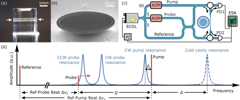
In this work we show direct measurements demonstrating that SPM and XPM split resonances at high-circulating powers in microresonators. More specifically, two continuous wave lasers at different frequencies can be simultaneously resonant in the same resonator mode with a frequency splitting that depends on the power difference between the two lasers. We directly measure the difference between the resonance shifts seen by a strong pump and a weak probe beam that is either copropagating or counterpropagating with the pump. Moreover, in the copropagating measurement, we observe a modified SPM-XPM mode splitting due to FWM contributions. To our knowledge, these are the first spectroscopic measurements of Kerr-effect-induced two-level and three-level splittings for continuous-wave lasers in optical resonators. Importantly, we demonstrate highly resolved splittings of many cavity linewidths, made possible by the extremely high Q-factors () with linewidths around 1 MHz. These fused silica microtoroids Armani et al. (2003) and microrod resonators Del’Haye et al. (2013) are shown in Fig. 1(a,b).
The SPM-XPM splitting occurs due to power differences between the pump and probe beams. For small probe powers, the Kerr-induced frequency shifts in the absence of FWM are
| (1) |
where is a proportionality constant. For the case in which the probe is copropagating with the pump, the factor of two between SPM-XPM can be reduced due to stimulated FWM Carman et al. (1966) taking place in addition to SPM and XPM. The decreased FWM-induced shift leads to a circulating-direction-dependent three-way splitting of the modes. FWM does not occur in the counterpropagating case as it would violate momentum conservation. This is also linked to recently observed resonance frequency splittings through Kerr-interaction with pulses from dissipative Kerr solitons Guo et al. (2017).
We use a weak probe laser to detect the splitting between SPM- and XPM-shifted resonances. To achieve this, we first split the light from a tunable laser source into three branches, as seen in Figs. 1(c) and 1(d), before recombining them into a single tapered fibre Knight et al. (1997) that is coupled to a wide microrod resonator ( Q-factor) Del’Haye et al. (2013). The pump branch (10 - 150 mW power) is up-shifted in frequency relative to the laser by a fixed amount ( ) using an acousto-optic modulator (AOM), and actively locked to a fixed detuning from its (thermally and SPM-shifted) resonance (see Fig. 1(d)). The transmitted pump power detected on the photodiode (PD2) is stabilised by a proportional-integral (PI) controller feeding back to the pump frequency. The active lock ensures that all other beams can be referenced relative to the pump frequency, and thus the thermally and SPM-shifted resonance. The thermally induced frequency shift affects the SPM- and XPM-resonance equally and only increases in Fig. 1(d), while the microresonator thermally self-stabilizes the pump resonance to the pump laser Carmon et al. (2004); Ilchenko and Gorodetskii (1992).
The probe branch AOM is scanned in frequency over a range of with respect to the pump laser AOM frequency (equivalent to linewidths). The frequency offset of the probe laser is shown as in Fig. 1(d). This allows us to perform spectroscopy around the pump frequency. Unlike the pump, the probe branch is coupled to the resonator in both directions. Importantly, the probe beams are too weak to induce any significant thermal or Kerr shifts on their own. The chosen resonance is far from neighbouring resonances, ensuring that the Kerr-shifted resonance is the one probed.
The reference branch light is used for heterodyne detection, while its frequency is far away from any resonance and constantly offset by from the pump laser. To measure the precise position of the XPM-shifted resonance, we electronically change to scan the probe laser across the resonance. Simultaneously, we monitor the power in the beat note between reference laser and probe laser , detected by PD1 and PD2 (see Fig. 1(c)). The beat note power is reduced when the laser crosses the XPM-shifted resonance. A complete trace of the XPM-shifted resonance (see Fig. 2) is obtained by continuously measuring the beat note power with an electronic spectrum analyser in “max hold” mode while sweeping the frequency . We also ensure that the polarisation of the pump, probe and reference are aligned with each other and with the resonator modes.
The dynamics of SPM- and XPM-induced resonance shifts in a microresonator are described by the following dimensionless equations for the clockwise/counterclockwise circulating intracavity fields:
| (2) |
where represents an external input field and where the pump and probe beams circulate in the CW and CCW directions respectively. Time is normalised by where is the cavity half-linewidth, and we are working in the rotating-wave approximation in the frame of the pump beam which is red-detuned from the cold cavity resonance by (normalised by ). Note the factor of two, arising due to XPM between the two beams. The dimensionless in-coupled powers and are normalised by the characteristic power
| (3) |
where and are coupled and intrinsic Q-factors respectively, is the resonator diameter, is the effective mode area, is the laser vacuum wavelength, and and are the linear and nonlinear refractive indices respectively. The pump powers and are normalised by where is the in-coupling efficiency for coupling half-linewidth and cavity half-linewidth .
We model a weak probe beam red-detuned by from the pump frequency, while the pump beam itself is red-detuned by from the cold cavity resonance, as seen in Fig. 1(d). Both and are dimensionless, normalised by the coupled resonator half-linewidth . The fields can thus be expressed (in the frame co-rotating with the pump beam) as
| (4) |
where and are the amplitudes of the external pump and probe beams respectively. Setting the time derivatives of these amplitudes to zero (), the intra-cavity amplitudes of the pump and probe beams, and respectively, satisfy
| (5) |
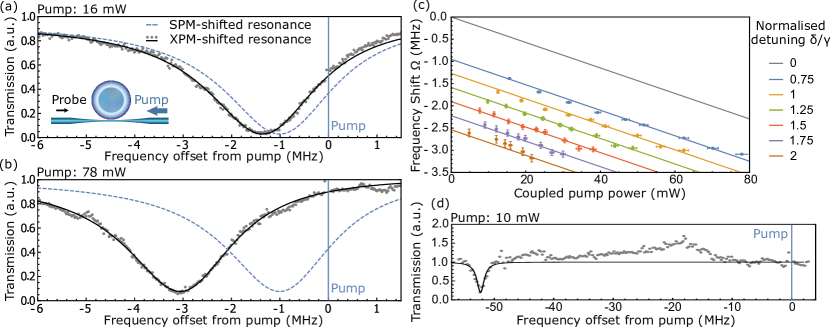
where we neglected the Kerr shifts due to since . The pump and probe beams experience SPM and XPM as seen by the factor of two difference in the Kerr shift. Thus, the scanning probe should measure a power-dependent resonance shift equivalent to the difference between the SPM and XPM. This is shown in Figs. 2(a) and 2(b), where an increase in the coupled pump power results in the scanning probe measuring the resonance further away from the pump frequency. From the intra-cavity fields, the pump and probe output fields are given by
| (6) |
where the fraction of light coupled out of the resonator can be found from by
| (7) |
with the plus and minus signs corresponding to over- and under-coupling respectively. The intensities of the pump and probe outputs are detected by the photodiodes as and , respectively.
Probe-scanning traces were taken for different pump detunings from the SPM-shifted resonance, , for a set of different coupled pump powers, as seen in Fig. 2(c). The in-coupled pump power is calculated by taking into account , , and . The difference between XPM resonance and the pump frequency is plotted against coupled power in Fig. 2(c) together with the associated fitting error. In each measurement, is fixed by locking the transmitted power to a specific value that depends on maximum (out of resonance) and minimum (on resonance) transmission values, and respectively, as follows:
| (8) |
Each consecutive trace in Fig. 2(c) corresponds to a increase of 0.25, with obtained from the Lorentzian fits. The (common) slope depends on both and , obtained from via (7), as well as the effective mode area , calculated to be . Fig. 2(c) also illustrates the trace. Experimentally, cavity thermal instabilities prevented us from obtaining low-detuning data Carmon et al. (2004).
For future applications, chip-based microresonators with lower nonlinear threshold powers like the microtoroid in Fig. 1(b) could be beneficial. Fig. 2(d) shows a measurement in a microtoroid with more than 35 cavity linewidths difference between XPM and SPM shift at 10 mW , corresponding to of power for inducing a one cavity linewidth frequency splitting.
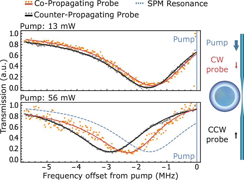
We were initially expecting that both the copropagating and counterpropagating resonances would undergo an identical shift in frequency, since XPM is independent of circulating direction. However, our probe spectroscopy measurements reveal an asymmetry in the shifts, such that the copropagating (CW) resonance undergoes less shift than originally expected. Moreover, an additional signal of the probe was detected mirrored around the pump frequency. The suggests the presence of FWM influencing the XPM-induced resonance shift. Degenerate FWM converts two pump photons into a probe and a signal photon, while the XPM-FWM interplay leads to a reduced resonance shift of the probe. The CW-CCW resonance shift difference is illustrated in Fig. 3. The resonator was probed simultaneously in both directions, suggesting that the pump interacted with the probe differently in the two directions, rather than the FWM decreasing the total power of the pump and hence the total shift. The data in Fig. 3 shows a threefold direction-dependent splitting of the cold cavity resonance.
Our model is thus modified in the case of a CW probe that copropagates with the pump, to account for this FWM-XPM interplay. Similarly to the CCW probe case, we start from the dynamical equation
| (9) |
that includes only clockwise-propagating light. We decompose the pump and circulating fields into frequency components as before, but additionally consider the presence of an intra-cavity ‘signal’ field resulting from FWM:
| (10) |
Substituting equation (10) into (9), and setting the time derivative of each component’s amplitude to zero (), we solve the equation such that it is true for all times . Thus, we derive the amplitudes of the intra-cavity pump, probe, and signal beams respectively to be
| (11) | ||||
Similarly to the counterpropagating case, the output fields can be expressed as in (6), with the addition of the signal , emerging at the mirrored probe detuning from the pump.
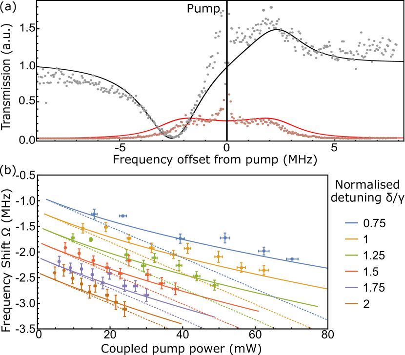
By plotting the output powers and with respect to the detuning , we show two very distinct characteristics of the spectrum, as shown in Fig. 4(a): first, the model predicts the generation of two peaks in the power of the signal beam, which occur when either the probe or signal coincides in frequency with the XPM-and-FWM-shifted resonance. The second characteristic feature of FWM predicted by our model is the small peak in the probe trace, seen in Fig. 4(a).
As illustrated in Fig. 4(b), our model shows the power-dependent frequency shift, for the same parameters used earlier to fit the counter-propagating data. Note that the CW and CCW probe measurements were taken simultaneously, and therefore correspond to the same resonance, coupling, and pump power. For comparison, the dotted lines in Fig. 4(b) correspond to the theoretical prediction without FWM for the CCW case. While the CW data exhibit bigger error bars due to pump noise in the frequency range of the measurement (since, unlike in the CCW case, the intense pump is incident on the same photodiode as the probe), our model still fits these data using the exact same parameters.
In conclusion, we have demonstrated resonance frequency splittings induced by XPM for continuous wave lasers in ultra-high-Q microresonators. The mode splittings are directly measured with a pump-probe spectroscopy scheme. In addition, we show that the XPM-FWM interplay can lead to a threefold resonance splitting. Using a microtoroid resonator, we show Kerr splittings of one cavity linewidth at very low powers of only . Resonance splitting of up to 35 cavity linewidths is observed at 10 mW optical power. With optical microresonators being building blocks for photonic integrated circuits, precise and fast control over their resonances is of critical importance. The optically induced splitting of resonances through the Kerr-nonlinearity at low power levels could enable new devices e.g. for coherent coupling of light to phonon modes that match the optical frequency splitting Schliesser et al. (2008); Vahala et al. (2009). More applications include optical memories and the use of microresonators for optically controlled modulators and filters.
Funded by H2020 European Research Council (ERC) (756966, CounterLight); H2020 Marie Sklodowska-Curie Actions (MSCA) (CoLiDR, 748519; GA-2015-713694); Engineering and Physical Sciences Research Council (EPSRC) (CDT for Controlled Quantum Dynamics, Applied Photonics, and Quantum Systems Engineering Skills Hub); Aker Scholarship; National Physical Laboratory (NPL), Max Planck Institute for the Science of Light (MPL).
References
- Hänsch (2006) T. W. Hänsch, Rev. Mod. Phys. 78, 1297 (2006).
- Del’Haye et al. (2007) P. Del’Haye, A. Schliesser, O. Arcizet, T. Wilken, R. Holzwarth, and T. J. Kippenberg, Nature 450, 1214 (2007).
- Foreman et al. (2015) M. R. Foreman, J. D. Swaim, and F. Vollmer, Adv. Opt. Photonics 7, 168 (2015).
- Heylman et al. (2017) K. D. Heylman, K. A. Knapper, E. H. Horak, M. T. Rea, S. K. Vanga, and R. H. Goldsmith, Adv. Mater. 29, 1700037 (2017).
- Ruesink et al. (2016) F. Ruesink, M.-A. Miri, A. Alu, and E. Verhagen, Nature communications 7, 13662 (2016).
- Enzian et al. (2019) G. Enzian, M. Szczykulska, J. Silver, L. Del Bino, S. Zhang, I. A. Walmsley, P. Del’Haye, and M. R. Vanner, Optica 6, 7 (2019).
- Peng et al. (2014) B. Peng, Ş. K. Özdemir, F. Lei, F. Monifi, M. Gianfreda, G. L. Long, S. Fan, F. Nori, C. M. Bender, and L. Yang, Nature Physics 10, 394 (2014).
- Del Bino et al. (2017) L. Del Bino, J. M. Silver, S. L. Stebbings, and P. Del’Haye, Scientific Reports 7, 43142 (2017).
- Cao et al. (2017) Q. T. Cao, H. M. Wang, C. H. Dong, H. Jing, R. S. Liu, X. Chen, L. Ge, Q. H. Gong, and Y. F. Xiao, Phys. Rev. Lett. 118, 033901 (2017).
- Woodley et al. (2018) M. T. M. Woodley, J. M. Silver, L. Hill, F. Copie, L. Del Bino, S. Y. Zhang, G. L. Oppo, and P. Del’Haye, Phys. Rev. A. 98, 053863 (2018).
- Kippenberg et al. (2004) T. Kippenberg, S. Spillane, and K. Vahala, Physical review letters 93, 083904 (2004).
- Savchenkov et al. (2004) A. A. Savchenkov, A. B. Matsko, D. Strekalov, M. Mohageg, V. S. Ilchenko, and L. Maleki, Physical review letters 93, 243905 (2004).
- Del Bino et al. (2018) L. Del Bino, J. M. Silver, M. T. M. Woodley, S. L. Stebbings, X. Zhao, and P. Del’Haye, Optica 5, 279 (2018).
- Haelterman (1991) M. Haelterman, Opt. Commun. 86, 189 (1991).
- Daniel and Agrawal (2012) B. A. Daniel and G. P. Agrawal, IEEE Photon. Technol. Lett. 24, 479 (2012).
- Bino et al. (2021) L. D. Bino, N. Moroney, and P. Del’Haye, Opt. Express 29, 2193 (2021).
- Moroney et al. (2020) N. Moroney, L. Del Bino, M. T. Woodley, G. N. Ghalanos, J. M. Silver, A. Ø. Svela, S. Zhang, and P. Del’Haye, J. Light. Technol. 38, 1414 (2020).
- Kaplan and Meystre (1981) A. E. Kaplan and P. Meystre, Opt. Lett. 6, 590 (1981).
- Wang and Search (2014) C. Wang and C. P. Search, Opt. Lett. 39, 4376 (2014).
- Silver et al. (2020) J. M. Silver, L. D. Bino, M. T. M. Woodley, G. N. Ghalanos, A. Ø. Svela, N. Moroney, S. Zhang, K. T. V. Grattan, and P. Del’Haye, arXiv preprint arXiv:2001.05479 (2020).
- Wang and Search (2015) C. Wang and C. P. Search, J. Light. Technol. 33, 4360 (2015).
- Bao et al. (2019) C. Bao, P. Liao, A. Kordts, L. Zhang, A. Matsko, M. Karpov, M. H. Pfeiffer, G. Xie, Y. Cao, A. Almaiman, M. Tur, T. J. Kippenberg, and A. E. Willner, Opt. Lett. 44, 1472 (2019).
- Suzuki et al. (2018) R. Suzuki, S. Fujii, A. Hori, and T. Tanabe, IEEE Photon. J. 11, 1 (2018).
- Zhang et al. (2020) S. Zhang, J. Silver, T. Bi, and P. Del’Haye, Nat. Commun. 11 (2020).
- Armani et al. (2003) D. Armani, T. Kippenberg, S. Spillane, and K. Vahala, Nature 421, 925 (2003).
- Del’Haye et al. (2013) P. Del’Haye, S. A. Diddams, and S. B. Papp, Appl. Phys. Lett. 102, 221119 (2013).
- Carman et al. (1966) R. Carman, R. Chiao, and P. Kelley, Phys. Rev. Lett. 17, 1281 (1966).
- Guo et al. (2017) H. Guo, M. Karpov, E. Lucas, A. Kordts, M. H. Pfeiffer, V. Brasch, G. Lihachev, V. E. Lobanov, M. L. Gorodetsky, and T. J. Kippenberg, Nat. Phys. 13, 94 (2017).
- Knight et al. (1997) J. C. Knight, G. Cheung, F. Jacques, and T. Birks, Opt. Lett. 22, 1129 (1997).
- Carmon et al. (2004) T. Carmon, L. Yang, and K. J. Vahala, Opt. Express 12, 4742 (2004).
- Ilchenko and Gorodetskii (1992) V. Ilchenko and M. Gorodetskii, Laser Phys. 2, 1004 (1992).
- Schliesser et al. (2008) A. Schliesser, R. Rivière, G. Anetsberger, O. Arcizet, and T. J. Kippenberg, Nat. Phys. 4, 415 (2008).
- Vahala et al. (2009) K. Vahala, M. Herrmann, S. Knünz, V. Batteiger, G. Saathoff, T. Hänsch, and T. Udem, Nat. Phys. 5, 682 (2009).