Anisotropic Particles Focusing Effect in Complex Flows
Abstract
Finite size effects can lead neutrally buoyant particles to exhibit different dynamics than tracer particles, and can alter their transport properties in fluid flows. Here we investigate the effect of the particle’s shape on their dispersion in 2-dimensional complex flows. Combining numerical simulations with laboratory experiments, we show that particles with isotropic and anisotropic shapes exhibit different Lagrangian coherent structures, resulting in distinct dispersion phenomena within a given flow field. Experiments with rod shaped particles show a focusing effect in the vicinity of vortex cores. We present a simple model that describes the dynamics of neutrally buoyant ellipsoidal particles in two-dimensional flow and show that particle aspect ratio and orientation dependent forces can generate clustering phenomena in vortices.
I Introduction
The dispersion of a tracer in a fluid flow is influenced by the Lagrangian motion of fluid elements. Even in laminar regimes, the irregular chaotic behavior of a fluid flow can lead to effective stirring that rapidly redistributes tracers throughout the domain. In this context, small finite-size objects can behave considerably different from infinitesimal fluid particles, and lead to altered clustering and dispersion phenomena. Ranging from pollutant transport [1] and plankton population evolution on the surface of the ocean [2], to interstellar dust dynamics [3, 4], quantifying the impact of finite-size effects is therefor essential to describe material transport in natural and industrial processes.
However, depending on their size and buoyancy properties, inertial particles can exhibit a variety of dynamics, resulting in markedly different trajectories [5, 6, 7, 8]. The shape of a particle can also affect its response to fluid flow [9, 10, 11, 12]. For instance, in cloud formation the anisotropic shapes of ice particles influence their transport [10, 13] and aggregation [14, 15] in turbulent atmospheric flows. Fiber transport in cellular flows, on the other hand, have been shown to exhibit hydrodynamic dispersion phenomena controlled by the buckling properties of the material [16, 17]. Under marine conditions, preferential alignment of elongated microorganisms in the local flow direction can affect light backscattering and change global carbon fixation rates within phytoplankton blooms [18]. In recent studies, predictive models suggested that the irregular shape of microplastic contaminants could also have an impact on their long term transport properties on the ocean surface [19, 20, 21].
In this paper, we investigate the effect of anistropic shape on the particles dynamics and long term behavior in chaotic flows. We experimentally show that when advected in two-dimensional cellular flows for an extended period of time, finite-size particles trajectories with an ellipsoidal shape start diverging from the spherical ones. The ellipsoidal particles exhibit a strong clustering in the vicinity of vortices with an aggregation rate that depends on the particle’s aspect ratio. We present a simple model that combines finite-size effects with an orientational-dependent dynamics, and perform in parallel, numerical simulations under identical conditions to the experiments. Our results suggest that neutrally buoyant ellipsoidal particles present stronger inertial effects, and are attracted to the coherent regions of the flow at a higher rate than spherical particles.
II Finite-size anisotropic particles dynamics
II.1 Isotropic inertial particles
Inertial effects arise when the advected particle and fluid flow accelerations become different; namely, the particle is responding to changes in the underlying flow field over a finite time and additional forces are generated. For instance when the particle density is different from the carrying fluid density, even for a small difference, these effects can accumulate over time and eventually lead to a drastic deviation between the fluid flow and particle trajectory. Experiments conducted in 3-dimensional turbulent flows [22, 7, 23, 24, 25], and in 2-dimensional chaotic flows [26, 6], have shown that the particles behavior can be partly quantified by the particle’s Stokes number :
| (1) |
where is the particle density, the fluid density, the particle radius, the flow characteristic length scale, and is the flow Reynolds number with the fluid kinematic viscosity. Assuming , the dynamics of small but finite-size inertial particles can be described with a simplified Maxey-Riley equation [27], neglecting the Faxén correction and memory terms [28, 26, 5, 29, 30]. After rescaling space by , and time by , with the characteristic flow velocity, the momentum equation becomes [29]
| (2) |
The particle’s velocity depends on three forces in the right hand side of the equation: the first term corresponds to advection and added mass, where is the flow velocity, the second term is the Stokes drag force, and the third term is the buoyancy force, where the density ratio is given by , and is gravity. Note that and are different here [26].
When the particles are neutrally buoyant, such that , and Equation (2) reduces to [29]
| (3) |
This shows that particles with finite number can still exhibit a dynamics with a finite relaxation time due to the flow interactions with the particle’s surface [26, 5, 6, 7]. Note that equation (3) converges toward the fluid elements motion when for infinitesimal particles.
II.2 Anisotropic particles angular dynamics
In comparison with spherical particles, anisotropic particles can exhibit additional torques and forces due to the coupling between their rotational and translational behavior. The motion of small, neutrally buoyant ellipsoidal particles in laminar flow has been first studied by G. B. Jeffery in 1922 [31]. His theoretical work on the torque experienced by non-inertial ellipsoidal particles combined with more recent numerical simulations with orientation dependent relaxation times [9, 32, 21], suggest that the dynamics of even very small objects, i. e. , could be affected by their anisotropic shape. Experiments in turbulent flow, have also indicated that the turbulent kinetic energy of a suspension is altered accordingly with the suspended particles’ shape [33]. Finally, numerical models with small inertial effects coupled with orientation dependent forces, showed that the transport of anisotropic particles under a wave can also lead to distinct behaviors over long period of times [21].
Neutrally buoyant ellipsoidal particles experience a torque that tends to align their principal axis parallel to the surrounding fluid principal axis of distortion. For non-inertial particles, the particle’s velocity is identical to the surrounding fluid at all time. In this situation, there is no resultant force and the torque acting on the particle vanishes at first order [31]. The particle angular velocity is then simply expressed as a function of the flow vorticity and strain-rate: [34, 35, 30]
| (4) |
where is the particle aspect ratio, with and the semi-minor and semi-major axes respectively, and and are the horizontal and vertical components of the flow velocity in the fixed frame. The particle’s orientational dynamics is described using 3 coordinate systems: a fixed frame , a particle frame , and a co-moving frame , see supplemental Fig. C.1 for a schematic [30]. In this configuration, corresponds to the angle between the particle’s major axis and or .
II.3 Anisotropic inertial particles
To describe the combined effects of finite-size and anisotropic shape with a minimal model, we present here an equation of motion that couples the particle’s orientation with the drag force only. In order to consider a finite-size particle, we need to take into account inertial forces that will tend to separate the particle’s trajectory from the fluid trajectory, such that now . The dynamics of anisotropic particles is not well approximated by equation (3) anymore, and need to be modified to account for the orientation specific dynamics [36, 37]. For instance, the added mass and drag force terms can become dependent to the particle’s instantaneous orientation [32, 9, 21]. Here, we use a linear momentum equation with a the hydrodynamic drag force term coupled with the ellipsoidal particle’s orientation [38, 39, 40, 41]
| (5) |
where is the radius of the equivalent sphere with the same volume as the ellipsoid, is the dynamic viscosity of the fluid and represents the resistance tensor of an ellipsoidal particle in the co-moving frame [40, 9]; see Supplemental Material for more details [30]. The resistance tensor is initially determined in the particle frame, and relates to in the co-moving frame through the particle’s rotation matrix , such that
| (6) |
In the case of a prolate ellipsoidal particle, e.g. invariant by rotation along its major axis, the resistance tensor reduces to a diagonal matrix, and for a 2-dimensional flow, we have
Substituting the drag force term applying to finite-size spheres in equation (3), and noting , we obtain
| (7) |
such that now, the equation of motion becomes coupled to the orientation of the particle given by equation (4). The drag force term’s prefactor is proportional to , indicating that the relaxation time of the particle will now also depend on its aspect ratio; i.e. the more elongated the particle the longer the response time. Similarly to Eq.(3), drag forces can introduce perturbations and also deviate elongated particles from fluid particle trajectories. Note that although the particles are passive, these perturbations allow the particles to cross flow streamlines and explore larger portions of the flow field, akin to active self-propelled particles [26, 42, 43, 44, 43]. However the dynamics exhibited by motile and inertial particles differ as they experience distinct forces. While prolate particles that can swim possess an intrinsic velocity aligned with the particle’s long axis at all times, passive particles on the other hand exhibit a distinct velocity from the fluid only when inertial forces are non negligible. These forces depend on both the particle’s orientation and the local flow geometry, such that, as opposed to motile particles with a fixed velocity, inertial particles intrinsic velocity can vary over time and point in different directions relative to the particle’s major axis.
III Materials and Methods
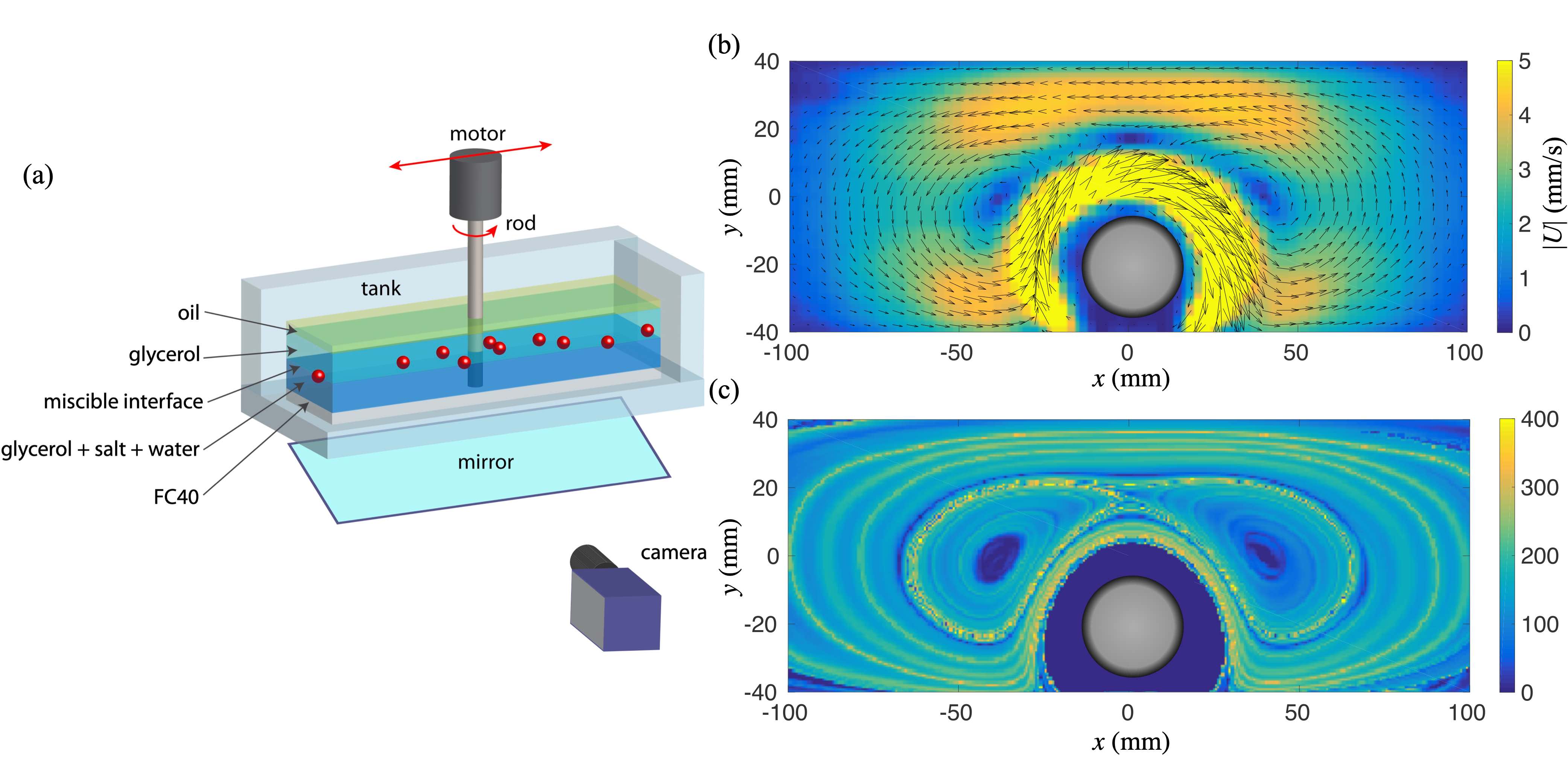
The experimental setup consists in a rectangular container of dimensions mm. To circumvent any surface tension effect [45], the particles are trapped at the interface between two miscible fluids of different density. The tank is filled with two stratified layers of pure glycerol with density and a solution of glycerol and salt with , as represented in Fig. 1(a). To prevent viscous instabilities at the interface, the viscosity of the layers are matched by adding water to the glycerol and salt solution. The particles have a density and are stabilized by buoyancy forces on a quasi-2-dimensional plane, see Supplemental Material for pictures [30]. The bottom of the tank is filled with a 1 cm layer of low viscosity fluorinated oil to reduce friction on the lower wall, and a layer of vegetable oil is added on top to prevent water absorption by the glycerol over time. The particles motion is recorded with a 45 degree tilted mirror at the bottom the setup, and particle tracking velocimetry (PTV) is performed from digitized images with a 14 bit LaVision camera.
We use 3D-printing ABS filament of mm diameter with variable length to create anisotropic particles of the desired aspect ratio. To minimize particle-particle interactions, a small number of particles (32) is initially uniformly deposited and spread across the domain. For each particle’s aspect ratio, five independent realizations were prepared manually by randomly redistributing the initial positions of the particles at the glycerol/glycerol-and-salt interface. Because of the stable stratification configuration and the high viscosity of the glycerol, the interface remained well define for several consecutive realizations of the experiment. The stratification is then renewed by changing the fluid mixture in the tank, and different particles are deposited at the interface.
The flow is created by stirring the fluid with a rotor attached to a longitudinal translation stage; see [46] for a similar experimental system description. The rotation is controlled with a Lexium NEMA 34 motion control motor with a cm diameter Plexiglas rod, and the translation of the rotor with a Parker lead-screw traverse attached on top of the tank. The resulting flow is quasi-2-dimensional in the stratified fluid layer, and similar to the rotor-oscillator flow topology described by Hackborn [47, 48, 30, 49]. In the steady regime, when the position of the rotor is fixed, the rotation of the rod close to the wall creates a hyperbolic stagnation point in the center and two Moffatt eddies [50] on each side of the rotor. Particle image velocimetry (PIV) is performed by seeding the upper glycerol layer with m diameter hollow glass beads. A YAG laser nm is used to illuminate a sheet in the horizontal plane and visualize the flow near the plane containing the inertial particles. A typical flow velocity snapshot is displayed in Fig. 1(b). The inner region in the direct proximity of the rotor exhibits the highest velocities , and rapidly decays within a rod radius away from the rotating boundary. The two co-rotating Moffatt eddies are also visible, with an average flow speed in the outer region of in their vicinity.
We perform in parallel numerical simulations solving the governing equations (3), (4) and (7) under identical conditions with the experiments.
The size and the aspect ratio of the particles are set by choosing identical Stokes number and with the experimental particles.
The particles initial positions are on a grid that matches our PIV field coverage, the initial orientation of the anisotropic particles are randomly chosen and the initial velocity is set slightly smaller than the fluid velocity at the particle’s location .
IV Numerical results
IV.1 Focusing effect in the steady double gyre flow
We first numerically investigate the effect of particle size and shape on their trajectories over a large range of Stokes number , and aspect ratio . We consider a double gyre flow with periodic boundary conditions defined by the streamfunction
| (8) |
where sets the flow amplitude, , and sets the oscillation amplitude. In the steady regime , and the streamfunction reduces to , leading to a simple periodic array of counter-rotating vortices.
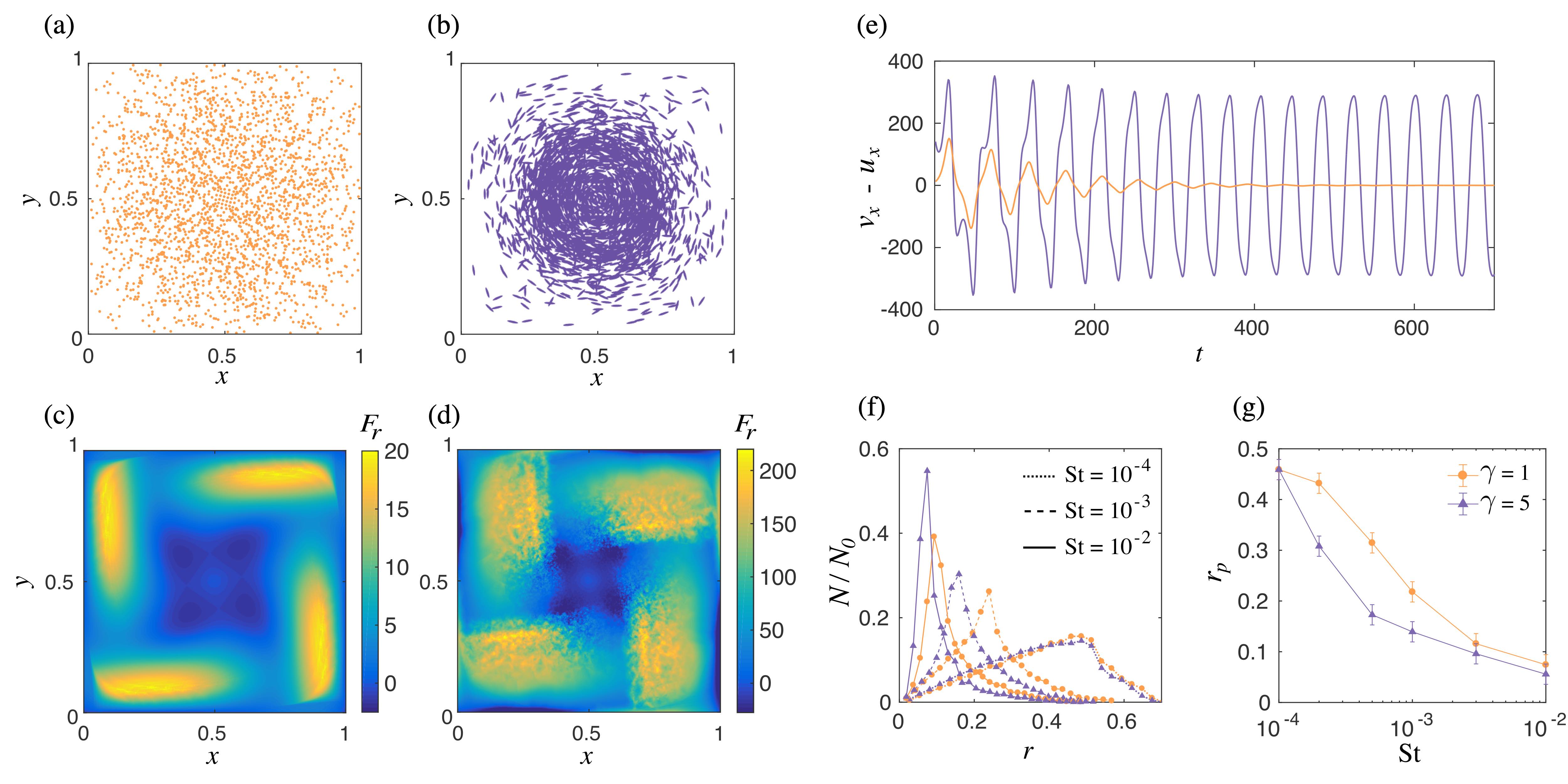
The resulting spatial distributions of neutrally buoyant particles with and different shapes around a single vortex are shown in Figs. 2(a) and 2(b). The streamfunction amplitude is set to , such that all the particles converge rapidly to a steady spatial distribution after a short transient regime and ellipsoidal particles orientation aligns with the local flow streamlines. Figures 2(c) and 2(d) show the corresponding radial component of the drag forces during the early transient dynamics. For both types of particles, a negative radial component is displayed near the center of the vortex, and indicates attractive forces toward this region of the flow. Drag forces are systematically larger for the ellipsoidal particles, leading to stronger deviations in average than for spherical particles. As can be seen in Fig. 2(e), even for the largest simulated Stokes number , spherical particles velocity rapidly relaxes toward the fluid flow velocity while elongated particles velocity doesn’t converge to the flow velocity. Anisotropic particles systematically present a stronger focusing effect, converging toward smaller orbit radii than the spherical particles at equal number. To illustrate this effect, we repeat the same simulation and vary the St number by two order of magnitude. Figure 2(f) shows the resulting radial distribution of particles in the steady regime. As the St number increases, the particles spatial distribution becomes more peaked and moves closer to the vortex center. As can be seen in Fig. 2(g), the distance of the particle density peak to the vortex center decreases faster for ellipsoidal particles as a function of the St number before becoming similar for both types of particles when .
Even at small number , when inertial effects are expected to be negligible for spherical particles, anisotropic particles exhibit a more complex dynamics with a stronger attraction to vortex cores.
IV.2 Particles dispersion in time-varying flows
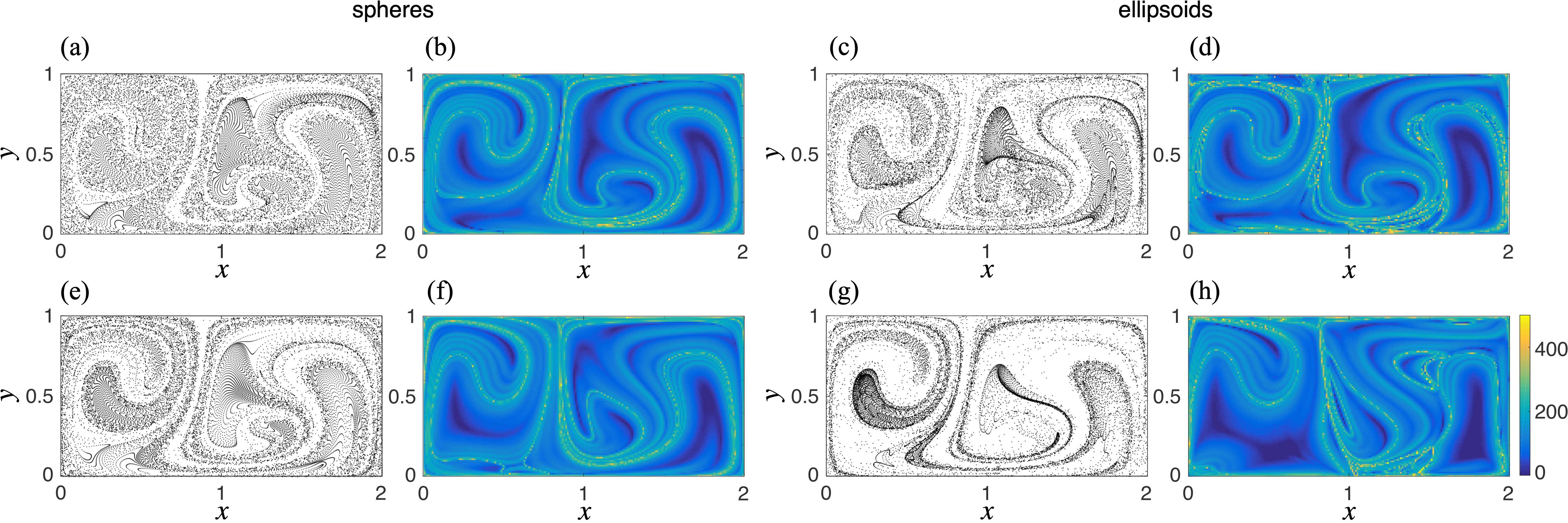
We now use the full time-dependent double gyre flow, and set . In time varying flows, attractive and repulsive structures are only defined over a finite-time period. In this context, Lagrangian coherent structures (LCS) provide a useful framework to understand the transport of material in complex, unsteady flow fields [1]. To identify these regions, we first compute the finite time Lyapunov exponent (FTLE) field corresponding to our flow and the inertial particles trajectories for a given time period [8, 30, 51, 52]. Regions with a low FTLE value are indicative of attractive properties; i.e. initially neighboring particles remain close to each other over a given time window, while regions with a high value correspond to repulsive regions of the flow, where the spatial separation over the same time window between neighboring fluid particles is maximum [53].
Figure 3 displays spatial distributions and corresponding FTLE fields for inertial particles with two different initial velocity and number. In all configurations, after , where is the gyre rotation frequency, the ellipsoidal particles distribution systematically present a more inhomogeneous spacial density variation than the spherical ones. At , the corresponding spherical particles FTLE field is similar to the flow FTLE field, see Supplemental Material [30]. The ellipsoidal particles FTLE fields are altered and exhibit additional structures located in regions with stronger shear. This suggests that in time varying flows, ellipsoidal particles more complex dynamics can lead to a departure from passive transport even at very small St numbers.
V Experimental results
V.1 Focusing effect in the rotor-flow
To test our findings, we perform a series of experiments and compare the resulting trajectories with our model by computing the numerical particles dynamics in the same, experimentally measured, flow field. The flow has the geometry of a rotor-flow in the steady regime, and a snapshot of the experimental velocity field with the corresponding FTLE field is shown in Figs. 1(b) and (c). We impose a constant rotor speed of rpm for all three different particle aspect ratio 1, 2 and 5. In this configuration, the Reynolds number typically ranges between in the flow central region, away from the direct vicinity of the rotor indicated by the gray disk in Figs. 1 and 4. This leads to relatively small particle Stokes number , such that, in the absence of anisotropic effects, we expect the particles with to behave closer to tracer particles in our experiments.
The particles are initially distributed uniformly across the experimental domain with no preferential alignment across the quasi-2-dimensional plane defined by the two-layer stratification, as described in the Method section [30]. The particles remain in the same plane for the entire duration of the experiments, and the principal axis of the elongated particles doesn’t display off-plane motions except near the rotor wall. Immediately after the flow is started, particles with change their orientation and exhibit a preferential alignment of their principal axis with the local flow direction, as shown in the supplemental movie 1 [30]. This suggests that the orientational behavior has a negligible response time to the changes in the flow field, in good agreement with equation (4), and previously reported findings for flows at higher Reynolds number [35, 10].
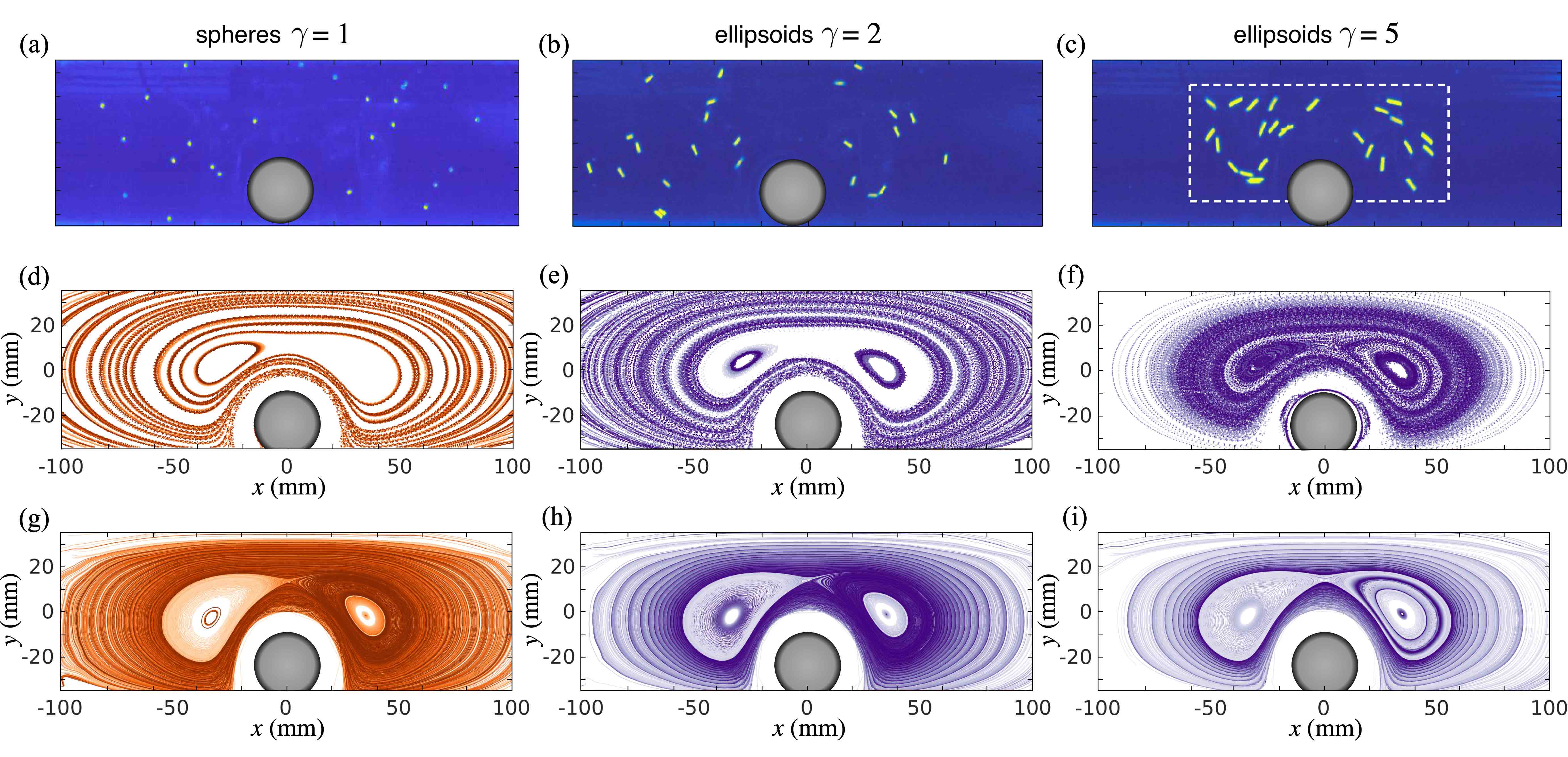
After a time , where s corresponds to the rotor rotation time period, the particles spatial distribution approaches a stationary regime which strongly depends on their aspect ratio, as shown in Figs. 4(a)-(c) and the supplemental movies 2-4 [30]. The final position of the particles with aspect ratio do not exhibit any preferential concentration, and remain uniformly spread across the domain, while particles with and display a migration from the outer regions of the flow into the vortex cores and their vicinity. Remarkably, for , all the particles are focused in the central region. Note that for and , some particles can be attracted to the secondary vortices located near the lateral edges of the tank not covered in our field of views in Figs. 1 and 4.
In order to quantify this behavior, we determine the individual particles trajectories using particle tracking velocimetry (PTV), and monitor their spatial distribution over time. Figures 4(d)-(f) display all the particles positions as a function of time for the entire duration of the experiment shown in Figs 4(a)-(c) respectively. As can be seen in Fig. 4(e) and 4(f), some of the elongated particles’ final trajectories form closed orbits inside the vortices. While for , the particles remain more evenly distributed outside the vortices, particles with exhibit a strong concentration in the direct vicinity of the vortices.
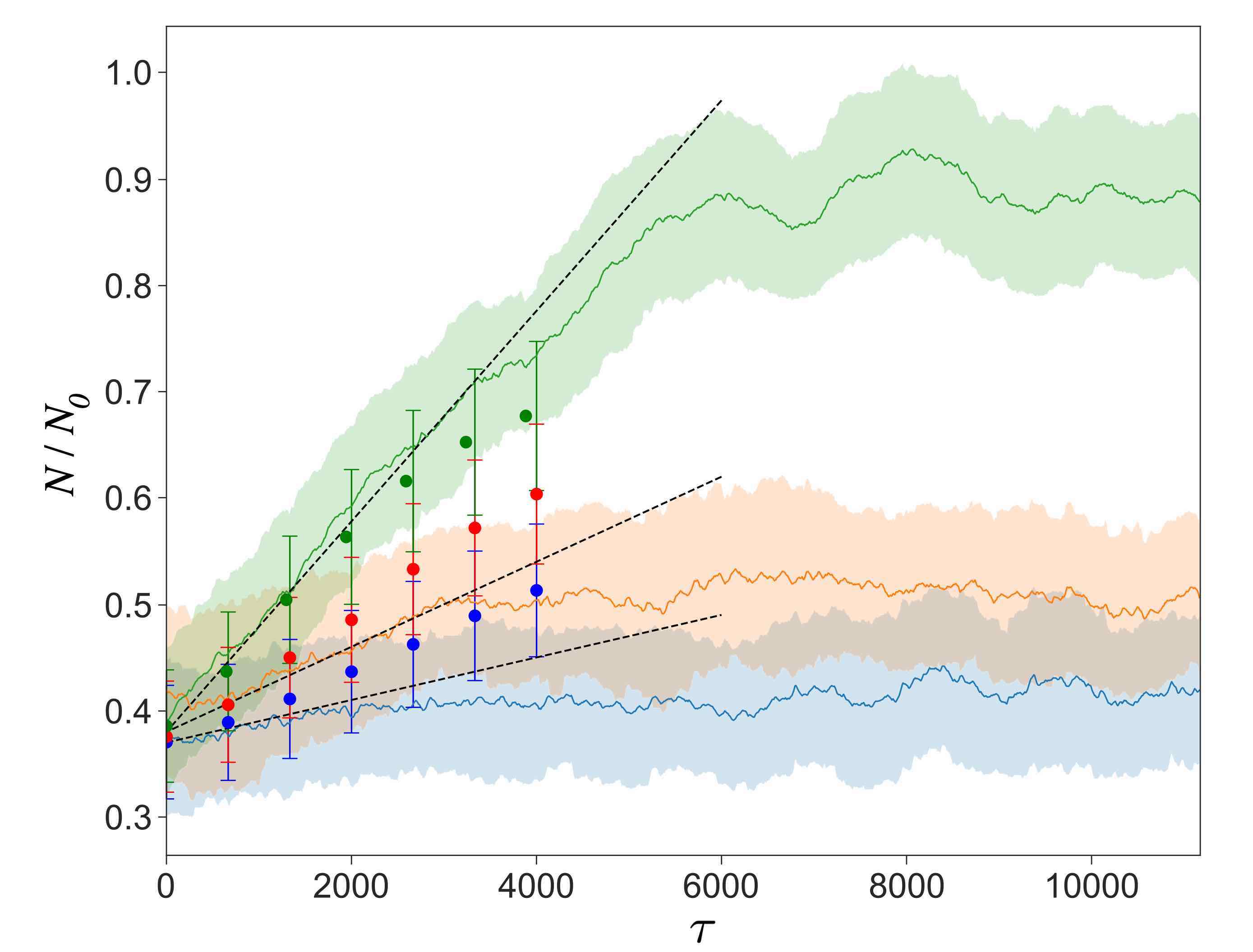
Figure 5 displays the measured particle density variation between in the central region of the flow delimited by the white dashed lines in Fig. 4(c). During a first transient regime, the spatial density of the elongated particles increases linearly over time and exhibit an aspect ratio dependent migration rate, with the largest rate for . After , the migration slows down and the density of particles in the central region of the flow converges toward a constant density over time. Interestingly, while both the migration rate and the final particle concentration depend on , the saturation time scale seems similar for particles with aspect ratio . Particles with present a negligible focusing effect, and their spatial distribution remains nearly unchanged over time.
V.2 Comparison with the numerical model
We perform in parallel numerical simulations using the experimentally measured flow field shown in Fig. 1(b). The particles number and aspect ratio are now chosen identical to the experimental particles. The flow field is first nondimensionalized as described in Supplemental Material [30]. We set with mm corresponding to the width of the tank, and , where is the characteristic flow velocity. To estimate from the experiments, we select the velocity that gives the best match between the numerical and experimental particles velocities located in identical regions of the flow. The best agreement with the experimental particles velocities is obtained for mm.s-1, in good agreement with the largest flow structures average velocity in Fig. 1(b).
The resulting numerical trajectories are shown in Figures 4(g)-(i), and qualitatively agree with the experimental trajectories spatial features. They display a similar convergence toward the vicinity of the vortices for , although a larger asymmetry between the left and right attractive regions within the vortices is visible, and only the right vortex traps the most elongated particles on a distinct inner orbit. The migration rate of the numerical particles are shown in Fig. 5, and display a similar trend with the experimental data in the transient regime. After , the predicted aggregation rates start differing from the experimental curves and lead to a less contrasted particle spatial distribution as a function of .
Comparing the shape of high particle concentration regions in our experiments and simulations with the rotor-flow FTLE field shown in Fig. 1(c), we can identify which flow structures attract the most the elongated particles. The flow FTLE field displays several ridges: two minima within the vortex cores corresponding to the two ellipsoidal regions where elongated particles are trapped in the experiments, and a third structure formed by the minima encircling the two vortices. Both experimental and numerical particles with the largest aspect ratio are specifically attracted to this third region and display the large closed orbit visible in Figs. 4(f) and 4(i).
VI Discussion
In our experiments, the observed migration toward vortices for elongated particles with a small Stokes number , suggests that even weak deviations from passive trajectories can build up over time, leading to distinct spatial organization over long time periods. These perturbations are not sufficient to significantly alter particles trajectories with an aspect ratio , and particles with exhibit a considerably weaker focusing effect than those with . A direct comparison of these observations with our numerical simulations shows that our minimal model qualitatively captures this behavior, although the particles focusing effect exhibits a smaller dependence to the particle aspect ratio than in the experiments. This difference could be attributed to second order orientation dependent terms, such as the added mass [36, 37, 32, 9, 21], that were neglected here.
These results suggest that anisotropic particles respond to the flow with a larger lag. In addition to the orientation dependent nature of the drag forces in equation (7), could be interpreted as an “effective” Stokes number that is proportional to . For weak inertial effects , the difference between and on the particles trajectories becomes only visible at large time scales, when small deviations have accumulated over longer time periods.
This effect could potentially enhance the migration rate of irregularly shaped objects such as microplastic in the ocean toward gyres of marine debris [20, 21], and influence the garbage patches formation dynamics [19, 54]. On the opposite length and time scales, in biology this interplay between the shape of the particle and the flow field geometry could influence the selective capture of microorganisms by larger animals. For instance, flows created by the beating of cilia can generate a local flow that attract only microorganisms of an optimal size [55]. Identical mechanisms could potentially select for an optimum shape, such as the aspect ratio of a given bacteria.
In conclusion, even neutrally buoyant particles with small particle Stokes number exhibit trajectories that deviate from the fluid flow when they possess an anisotropic shape. Both experimental and numerical particles exhibit a migration toward regions in the vicinity of vortices. The orientational dependence of the drag force term in our minimal model describes qualitatively the particles dynamics, suggesting that this mechanisms could be the dominant effect for the separation of isotropic and anisotropic particle trajectories in cellular flows. In addition, the effect of additional orientation dependent terms and experiments with unsteady flows should be investigated in future work.
VII Acknowledgments
The authors would like to thank A.W. Murray and E. Climent for stimulating discussions, G. Haller, T. Witten and E. Kanso for their thought provoking comments. S. A. was supported by the French government DGA/DS - Mission pour la Recherche et l’Innovation Scientifique fellowship during her visit at MIT. T. P. acknowledges funding from ONR Grant N000141812762.
References
- Peacock and Haller [2013] T. Peacock and G. Haller, Lagrangian coherent structures The hidden skeleton of fluid flows, Physics Today 66, 41 (2013).
- Abraham [1998] E. R. Abraham, The generation of plankton patchiness by turbulent stirring, Nature 391, 577 (1998).
- Gold [1952] T. Gold, The alignment of galactic dust, Monthly Notices of the Royal Astronomical Society 112, 215 (1952).
- Andersson et al. [2015] B. Andersson, A. Lazarian, and J. E. Vaillancourt, Interstellar dust grain alignment, Annual Review of Astronomy and Astrophysics 53, 501 (2015).
- Haller and Sapsis [2008] G. Haller and T. Sapsis, Where do inertial particles go in fluid flows?, Physica D-nonlinear Phenomena 237, 573 (2008).
- Ouellette et al. [2008] N. T. Ouellette, P. J. J. O’Malley, and J. P. Gollub, Transport of Finite-Sized Particles in Chaotic Flow, Physical Review Letters 101, 174504 (2008).
- Brown et al. [2009] R. D. Brown, Z. Warhaft, and G. A. Voth, Acceleration Statistics of Neutrally Buoyant Spherical Particles in Intense Turbulence, Physical Review Letters 103, 194501 (2009).
- Sudharsan et al. [2016] M. Sudharsan, S. L. Brunton, and J. J. Riley, Lagrangian coherent structures and inertial particle dynamics, Physical Review E 93, 033108 (2016).
- Zhang et al. [2001] H. F. Zhang, G. Ahmadi, F. G. Fan, and J. B. McLaughlin, Ellipsoidal particles transport and deposition in turbulent channel flows, International Journal of Multiphase Flow 27, 971 (2001).
- Ni et al. [2014] R. Ni, N. T. Ouellette, and G. A. Voth, Alignment of vorticity and rods with Lagrangian fluid stretching in turbulence, Journal of Fluid Mechanics 743, R3 (2014).
- Parsa et al. [2012] S. Parsa, E. Calzavarini, F. Toschi, and G. A. Voth, Rotation rate of rods in turbulent fluid flow, Physical review letters 109, 134501 (2012).
- Voth and Soldati [2017] G. A. Voth and A. Soldati, Anisotropic particles in turbulence, Annual Review of Fluid Mechanics 49, 249 (2017).
- Jucha et al. [2018] J. Jucha, A. Naso, E. Lévêque, and A. Pumir, Settling and collision between small ice crystals in turbulent flows, Physical Review Fluids 3, 014604 (2018).
- Saw et al. [2008] E. W. Saw, R. A. Shaw, S. Ayyalasomayajula, P. Y. Chuang, and A. Gylfason, Inertial clustering of particles in high-reynolds-number turbulence, Physical Review Letters 100, 214501 (2008).
- Squires and Eaton [1990] K. D. Squires and J. K. Eaton, Particle Response and Turbulence Modification In Isotropic Turbulence, Physics of Fluids A-fluid Dynamics 2, 1191 (1990).
- Wandersman et al. [2010] E. Wandersman, N. Quennouz, M. Fermigier, A. Lindner, and O. Du Roure, Buckled in translation, Soft matter 6, 5715 (2010).
- Quennouz et al. [2015] N. Quennouz, M. Shelley, O. Du Roure, and A. Lindner, Transport and buckling dynamics of an elastic fibre in a viscous cellular flow, J Fluid Mech 769, 387 (2015).
- Marcos et al. [2011] Marcos, J. R. Seymour, M. Luhar, W. M. Durham, J. G. Mitchell, A. Macke, and R. Stocker, Microbial alignment in flow changes ocean light climate, Proceedings of the National Academy of Sciences of the United States of America 108, 3860 (2011).
- Broday, D and Fichman, M and Shapiro, M and Gutfinger [1997] C. Broday, D and Fichman, M and Shapiro, M and Gutfinger, Motion of diffusionless particles in vertical stagnation flows—II. Deposition efficiency of elongated particles, Journal of Aerosol Science 28, 35 (1997).
- Chubarenko et al. [2016] I. Chubarenko, A. Bagaev, M. Zobkov, and E. Esiukova, On some physical and dynamical properties of microplastic particles in marine environment, MPB 108, 105 (2016).
- Dibenedetto et al. [2018] M. H. Dibenedetto, N. T. Ouellette, and J. R. Koseff, Transport of anisotropic particles under waves, , 320 (2018).
- La Porta et al. [2001] A. La Porta, G. A. Voth, A. M. Crawford, J. Alexander, and E. Bodenschatz, Fluid particle accelerations in fully developed turbulence, Nature 409, 1017 (2001).
- Volk et al. [2011] R. Volk, E. Calzavarini, E. Leveque, and J. . F. Pinton, Dynamics of inertial particles in a turbulent von Karman flow, Journal of Fluid Mechanics 668, 223 (2011).
- Calzavarini et al. [2012] E. Calzavarini, R. Volk, E. Leveque, J.-F. Pinton, and F. Toschi, Impact of trailing wake drag on the statistical properties and dynamics of finite-sized particle in turbulence, Physica D-nonlinear Phenomena 241, 237 (2012).
- Klein et al. [2013] S. Klein, M. Gibert, A. Berut, and E. Bodenschatz, Simultaneous 3D measurement of the translation and rotation of finite-size particles and the flow field in a fully developed turbulent water flow, Measurement Science & Technology 24, 24006 (2013).
- Babiano et al. [2000] A. Babiano, J. H. Cartwright, O. Piro, and A. Provenzale, Dynamics of a small neutrally buoyant sphere in a fluid and targeting in hamiltonian systems, Physical Review Letters 84, 5764 (2000).
- Maxey and Riley [1983] M. R. Maxey and J. J. Riley, Equation of Motion For A Small Rigid Sphere In A Nonuniform Flow, Physics of Fluids 26, 883 (1983).
- Michaelides [1997] E. E. Michaelides, The Transient Equation of Motion for Particles, Bubbles, and Droplets, Journal of fluids engineering 119, 233 (1997).
- Sapsis et al. [2011] T. P. Sapsis, N. T. Ouellette, J. P. Gollub, and G. Haller, Neutrally buoyant particle dynamics in fluid flows: Comparison of experiments with Lagrangian stochastic models, Physics of Fluids 23, 93304 (2011).
- [30] See Supplemental Material at [URL will be inserted by publisher] for additional details and movies description .
- Jeffery [1922] G. B. Jeffery, The motion of ellipsoidal particles in a viscous fluid, Proceedings of the Royal Society of London Series A-containing Papers of A Mathematical and Physical Character 102, 161 (1922).
- Mortensen et al. [2008] P. H. Mortensen, H. I. Andersson, J. J. J. Gillissen, and B. J. Boersma, Dynamics of prolate ellipsoidal particles in a turbulent channel flow, Physics of Fluids 20, 93302 (2008).
- Bellani et al. [2012] G. Bellani, M. L. Byron, A. G. Collignon, C. R. Meyer, and E. A. Variano, Shape effects on turbulent modulation by large nearly neutrally buoyant particles, Journal of Fluid Mechanics 712, 41 (2012).
- Olson and Kerekes [1998] J. A. Olson and R. J. Kerekes, The motion of fibres in turbulent flow, Journal of Fluid Mechanics 377, 47 (1998).
- Parsa et al. [2011] S. Parsa, J. S. Guasto, M. Kishore, N. T. Ouellette, J. P. Gollub, and G. A. Voth, Rotation and alignment of rods in two-dimensional chaotic flow, Physics of Fluids 23, 43302 (2011).
- Gallily and Cohen [1979] I. Gallily and A. H. Cohen, Orderly Nature of the Motion of Nonspherical Aerosol-particles .2. Inertial Collision Between A Spherical Large Droplet and An Axially Symmetrical Elongated Particle, Journal of Colloid and Interface Science 68, 338 (1979).
- Koch and Shaqfeh [1989] D. L. Koch and E. S. G. Shaqfeh, The Instability of A Dispersion of Sedimenting Spheroids, Journal of Fluid Mechanics 209, 521 (1989).
- Brenner [1964a] H. Brenner, The Stokes Resistance of An Arbitrary Particle .3. Shear Fields, Chemical Engineering Science 19, 631 (1964a).
- Brenner [1964b] H. Brenner, The Stokes Resistance of An Arbitrary Particle .4. Arbitrary Fields of Flow, Chemical Engineering Science 19, 703 (1964b).
- Fan and Ahmadi [1995] F.-G. Fan and G. Ahmadi, Dispersion of ellipsoidal particles in an isotropic pseudo-turbulent flow field, Journal of fluids engineering 117, 154 (1995).
- Loth [2008] E. Loth, Drag of non-spherical solid particles of regular and irregular shape, Powder Technology 182, 342 (2008).
- Torney and Neufeld [2007] C. Torney and Z. Neufeld, Transport and aggregation of self-propelled particles in fluid flows, Physical review letters 99, 078101 (2007).
- Khurana et al. [2011] N. Khurana, J. Blawzdziewicz, and N. T. Ouellette, Reduced transport of swimming particles in chaotic flow due to hydrodynamic trapping, Physical review letters 106, 198104 (2011).
- Durham et al. [2011] W. M. Durham, E. Climent, and R. Stocker, Gyrotaxis in a steady vortical flow, Physical Review Letters 106, 238102 (2011).
- Vella and Mahadevan [2005] D. Vella and L. Mahadevan, The “Cheerios effect”, American Journal of Physics 73, 817 (2005).
- Filippi et al. [2020] M. Filippi, M. Budišić, M. R. Allshouse, S. Atis, J.-L. Thiffeault, and T. Peacock, Using braids to quantify interface growth and coherence in a rotor-oscillator flow, Physical Review Fluids 5, 054504 (2020).
- Hackborn [1990] W. W. Hackborn, Asymmetric Stokes flow between parallel planes due to a rotlet, Journal of Fluid Mechanics 218, 531 (1990).
- Hackborn et al. [1997] W. W. Hackborn, M. E. Ulucakli, and T. Yuster, A theoretical and experimental study of hyperbolic and degenerate mixing regions in a chaotic Stokes flow, Journal of Fluid Mechanics 346, 23 (1997).
- Weldon et al. [2008] M. Weldon, T. Peacock, G. B. Jacobs, M. Helu, and G. Haller, Experimental and numerical investigation of the kinematic theory of unsteady separation, Journal of Fluid Mechanics 611, 1 (2008).
- Moffatt [1964] H. K. Moffatt, Viscous and resistive eddies near a sharp corner, Journal of Fluid Mechanics 18, 1 (1964).
- Pierrehumbert and Yang [1993] R. T. Pierrehumbert and H. Yang, Global Chaotic Mixing On Isentropic Surfaces, Journal of the Atmospheric Sciences 50, 2462 (1993).
- Haller [2001] G. Haller, Distinguished material surfaces and coherent structures in three-dimensional fluid flows, Physica D 149, 248 (2001).
- Haller [2015] G. Haller, Lagrangian coherent structures, Annual Review of Fluid Mechanics 47, 137 (2015).
- van Sebille et al. [2012] E. van Sebille, M. H. England, and G. Froyland, Origin, dynamics and evolution of ocean garbage patches from observed surface drifters, Environmental Research Letters 7, 44040 (2012).
- Ding and Kanso [2015] Y. Ding and E. Kanso, Selective particle capture by asynchronously beating cilia, Physics of Fluids 27, 121902 (2015).