SmartArm: Suturing Feasibility of a Surgical Robotic System on a Neonatal Chest Model
Abstract
Commercially available surgical-robot technology currently addresses many surgical scenarios for adult patients. This same technology cannot be used to the benefit of neonate patients given the considerably smaller workspace. Medically relevant procedures regarding neonate patients include minimally invasive surgery to repair congenital esophagus disorders, which entail the suturing of the fragile esophagus within the narrow neonate cavity. In this work, we explore the use of the SmartArm robotic system in a feasibility study using a neonate chest and esophagus model. We show that a medically inexperienced operator can perform two-throw knots inside the neonate chest model using the robotic system.
Index Terms:
medical robotics, kinematics, neonate surgery, suturing.I Introduction
Neonate patients cannot currently benefit from commercial surgical-robot technology, which mostly targets adult patients [1, 2, 3]. Medically significant applications for neonatal patients that could highly benefit from robotic assistance include the treatment of congenital disorders in the esophagus, two of those being tracheoesophageal fistula (TEF) and esophageal atresia (EA).
TEF is a disorder in which the newborn has a connection between the esophagus and the trachea and those must be surgically separated. EA is a condition in which the esophagus of the newborn is formed in two disconnected parts that have to be surgically reconnected. The most challenging step in both surgical procedures is to suture or anastomose the tiny esophagus/trachea of the neonate patient. In general, this part of the procedure is viewed through a 4-mm-diameter endoscope, and the suture is handled by a 3-mm-diameter forceps and a 3-mm-diameter needle driver [4].
The constrained workspace in neonatal patients is a technical challenge that has to be addressed in many fronts. Advancements in anatomically proper chest and esophagus models for pediatric surgical training [5] are an important element to support the development of surgical robot technology and provide an ethical benchmark to the evaluation of surgical skill.
Our group and collaborators have been using such models to support the development of technologies that compose the SmartArm surgical system [6]. The technologies include the development of thin dexterous robotic instruments [7], suitable teleoperation algorithms [8], and collision avoidance strategies [9]. The SmartArm has been validated in an endonasal procedure using the head model of an adult patient [6], and in prior related work we showed a proof-of-concept of the underlying technologies required for robotic assistance in procedures targeting infants [8].
Statement of contribution
Based on those initial results, in this work, we investigate the feasibility of using the SmartArm to suture an esophageal model developed for the training of TEF and EA surgeries. To the best of the authors’ knowledge, intracorporeal suturing in the context of TEF and EA for neonatal patients have not yet been addressed by robotic surgery.
II Materials and methods
II-A Neonate surgical setup
The robotic setup can be divided into the patient side (PS) and the operator side (OS), explained as follows.
II-A1 Patient side
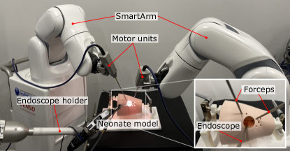
Each six-degrees-of-freedom (6-DoF) robotic manipulator (VS050, Denso Wave, Japan) that compose the SmartArm system were placed at opposing sides of a neonate model. Each of those robotic manipulators was equipped with a 3-DoF 20-cm-long 3.5-mm-diameter instrument [7]. Hence, each of the robots, , had nine DoF. In addition, the view of the workspace was obtained through a rigid endoscope111Rigid endoscopes can have a prism attached to their distal end to incline the direction of view. The choice of angle is based on the task and on the user. held by an endoscope holder (Endoarm, Olympus, Japan). An overview of the PS is shown in Fig. 1.
II-A2 Operator side
The OS of the setup was composed of two haptic interfaces (Phantom Premium, 3DSystems, USA) with a customized stylus [10]. Each of those interfaces sent the desired pose signals to one of the robots in the PS.
II-B Control strategy
The control strategy used in this work is a particular case of the control strategy introduced in [6, Section IV], and is divided into a quadratic-programming (QP)-based controller on the PS and a Cartesian impedance controller on the OS. The control strategy is explained in Sections II-B1 and II-B2.
II-B1 Patient side
Let the vector of joint configurations for each robot in the PS be given by for The PS control is based on sending at each time step the joint-velocity reference signal222In optimization literature, a minimizer is usually denoted with a superscript asterisk, such as . Here we use the superscript to avoid notational confusion with the quaternion conjugate. to the joint-velocity controllers of each robot. The joint velocities are obtained by solving333The solution of QP problems is obtained through a numerical solver. at each time step and in parallel for each robot the following QP problem
| (1) | ||||
| subject to |
where , , and are the cost functions related to the end-effector translation444The translation is written as a pure quaternion in the form with and . Moreover, , ; the end-effector rotation555The rotation is written as a unit quaternion in the form where is the angle of rotation about the unit-axis defined by the pure quaternion . In addition, Note that is the conjugate of and represents the inverse rotation., ; and joint velocities of the -th robot, respectively. In addition, each -th robot has a translation Jacobian , a translation error , a rotation Jacobian , and a switching rotational error given by
based on the dual quaternion invariant error [11], where and are the desired and current end-effector orientations, respectively. The switching error is used to circumvent the unwinding problem given that the group of unit quaternions double covers [12]. This way, if is closer to , the error is given by ; conversely, if is closer to , the error is given by . The desired translation signals, , and rotational signals, , are defined by the operator handling the haptic interfaces in the OS. Furthermore, is a proportional gain to reduce the task error and is a positive definite damping matrix in the form
where are used to balance the costs of using joints in the robot and in the forceps, and and stand for the identity and zero matrices, respectively. Lastly, is a weight used to define the (soft) priority between the translation and the rotation. The parameter only visibly affects the system when the robot is unable to simultaneously achieve the desired error convergence rate for both rotation and translation owing to task-space or joint-space constraints. The parameter is often found empirically for a given user and a given task [8, 6]. This gives the designer more flexibility than resorting to nested optimization algorithms [13], which would also increase the computational time.
The linear constraints are used in the following way
| (2) |
where and are used to maintain the joint values within their lower and upper bounds, given by and respectively [14].
For procedures in the constrained workspace inside neonate patients, medical doctors have to take advantage of the natural compliance of the patient’s skin. This constraint is called an entry-sphere as represented in Fig. 2. To generate an entry-sphere constraint for each robotic instrument, we used and , where is the line-to-point distance Jacobian [9, Eq. 34] relating the distance between the center-line of the shaft of the instrument of the th robot and the point representing the center of the entry-sphere for that instrument. In addition, is the square-distance between the center of the entry-sphere and the centerline of the shaft of the instrument [9, Eq. 33] and is the maximum allowed square distance. Lastly, is a gain that limits the velocity in which the robot can move towards the boundaries of the entry-sphere constraint. This technique provides smooth collision avoidance and guarantees that the constraints will not be violated [9].
Stability
Existence and uniqueness of a solution
There will always be a solution to Problem 1 as long as the constraints are not initially violated because this means that is always a feasible solution. This premise is valid for the present surgical robotic application given that the robot will be safely placed inside the patient without violating the constraints during the initial setup. Related literature indicates that the solution of Problem 1 will always be unique if [13, 16], because the objective function becomes strictly convex.
II-B2 Operator side
In order to provide haptic guidance to the operator, we add the standard Cartesian force feedback on the OS for each haptic interface. The Cartesian force feedback is proportional to the current task-space error of the robots in the PS, in the form
| (3) |
where is the force feedback on the OS, are, respectively, stiffness and viscosity parameters, is the translation error of the robots in the PS, but seen from the point of view of the OS, and is the linear velocity of that haptic device. This proportional force feedback with viscosity allows the operator to “feel” any task-space directions in which the robot has difficulty moving. The motion-scaling (MS) is the ratio between the motion in the PS induced by the motion in the OS. It is important to note that in the current setup the SmartArm is not equipped with force sensors in the instruments and cannot sense forces applied to the environment. Further work is needed analyze the stability of the combination of Problem 1 in the PS with the force-feedback term (3) in the OS in addition to operator effects.
II-C Software implementation
III Experiments
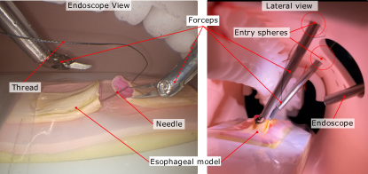
We designed an experiment to validate the SmartArm system in a suturing task within the limited workspace of a neonate chest model. The chest and esophageal models are being developed at Nagoya University by a group of medical doctors. It is important to note that this is a feasibility study; hence it was not designed to evaluate if the SmartArm provides a better suturing experience than manual surgery. An external view of the experimental setup is as shown in Fig. 1, and a lateral view from inside the neonate model is shown in Fig. 2.
An operator inexperienced in actual surgical procedures was asked to tie, using the SmartArm system, a two-throw surgical knot connecting both sides of the esophageal model for a total of ten trials. In each trial, the operator handled a suture commonly used in pediatric surgery (5-0 PERMA-HAND SILK 13 mm 3/8c, Ethicon, USA). The thread was cut to have a length of mm.
For the purpose of time-keeping, the task started from when the operator touched the esophageal model with the tip of the needle while holding the needle with the robotic forceps. The task was considered to be over when the operator finished a solid two-throw knot, that is, a knot that could no longer be tightened in spite of pulling the thread. This time-keeping methodology is similar to the one we used for endonasal experiments [6] and helps to standardize the results.
| MS | ||||||||
|---|---|---|---|---|---|---|---|---|
| 0.9999 | 120 | 1 | 0.0052 | 0.01 | 0.0 | 100 | 10 | 1 |
A summary of the control parameters used in this work is shown in Table I. Note that the parameters were tuned in pilot trials until the user was comfortable with the robot behavior and kept constant through all the experimental trials reported herein. An is recommended for teleoperation where translation signals are in millimeter scale compared to rotational changes that can be in the range of several degrees. The proportional gain was chosen as and should be set as large as possible without causing the system to vibrate777Vibrations owing to the choice of parameters are inherent to the discrete-time implementation and not caused by the algorithm itself.. The entry-sphere gain was set as and can be as large as possible without causing the system to vibrate near the constraint boundaries. The safe distance was set to generate a 5 mm radius sphere as indicated by medical doctors. We chose in contrast with as damping factors, because in this context it is reasonable to have the robot preferably move the forceps DoF instead of the manipulator’s DoF whenever possible. This is motivated by the fact that the forceps DoF carry negligible weight and have less associated inertia when compared to the manipulators’ DoF.
IV Results and discussion
| T1 | T2 | T3 | T4 | T5 | T6 | T7 | T8 | T9 | T10 | |
|---|---|---|---|---|---|---|---|---|---|---|
| Time [s] | 1421 | 416 | 338 | 559 | 468 | 381 | 229 | 216 | 305 | 684 |
In a neonate surgical scenario, an expert surgeon is expected to be able to tie a knot in less than 5 min [5]. Our medically inexperienced operator was able to reach that mark twice, and we expect that a medically experienced operator with proper training would have better results.
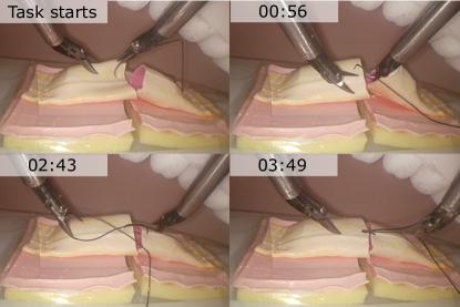
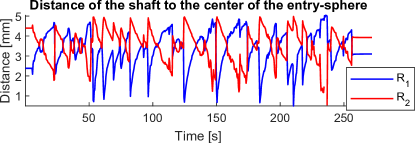
The total time spent in each trial is summarized in Table II. Snapshots of the important timestamps of T7 are shown in Fig. 3. The distance of the center-line of the shaft of each instrument with respect to the center of its entry-sphere during T7 is shown in Fig. 4. The distance was measured using encoder information and the robot kinematic model and does not take into account possible elasticity effects of the long shaft.
The results shown in [5, Table 4], , regard manual procedures performed by expert and qualified surgeons in similar conditions but with different neonate chest and esophageal models. Compared to Table II, this is evidence that suturing with the SmartArm robot inside the neonate model is feasible within a reasonable time-frame. Prior literature [5, 3, 6] indicates that 5 min can be considered an upper-bound for expert-level suturing. Given the promising results in this feasibility study, we plan on carrying this research onto the next stage and compare manual and robot-assisted procedures in the same conditions with the participation of surgeons.
V Conclusions
In this work, we investigated the use of a versatile robotic system for surgery, called SmartArm, in suturing experiments using neonate esophageal and chest models. The results of this feasibility study show, for the first time in the literature, successful robot-aided suturing trials inside a neonate model.
Total task-time is not the only important dimension in evaluating performance in suturing. In future work, we will evaluate the performance of the SmartArm system when compared to the manual procedure also in terms other important performance metrics, such as precision and workload.
References
- [1] A. Thakre, Y. Bailly, L. Sun, F. V. Meer, and C. Yeung, “Is smaller workspace a limitation for robot performance in laparoscopy?” Journal of Urology, vol. 179, no. 3, pp. 1138–1143, 2008.
- [2] T. P. Cundy, H. J. Marcus, A. Hughes-Hallett, T. MacKinnon, A. S. Najmaldin, G.-Z. Yang, and A. Darzi, “Robotic versus non-robotic instruments in spatially constrained operating workspaces: a pre-clinical randomized crossover study,” BJU International, vol. 116, no. 3, pp. 415–422, 2015.
- [3] S. Takazawa et al., “Evaluation of surgical devices using an artificial pediatric thoracic model: A comparison between robot-assisted thoracoscopic suturing versus conventional video-assisted thoracoscopic suturing,” Journal of Laparoendoscopic & Advanced Surgical Techniques, vol. 28, no. 5, pp. 622–627, 2018.
- [4] K. Deie and T. Iwanaka, “Thoracoscopic operation for esophageal atresia,” in Operative General Surgery in Neonates and Infants. Springer Japan, 2016, pp. 111–117.
- [5] K. Harada et al., “Development of a neonatal thoracic cavity model and preliminary study,” Journal of Japan Society of Computer Aided Surgery, vol. 18, no. 2, pp. 80–86, 2016.
- [6] M. M. Marinho et al., “SmartArm: Integration and validation of a versatile surgical robotic system for constrained workspaces,” The International Journal of Medical Robotics and Computer Assisted Surgery, 2020.
- [7] J. Arata et al., “Compliant four degree-of-freedom manipulator with locally deformable elastic elements for minimally invasive surgery,” in 2019 IEEE International Conference on Robotics and Automation (ICRA), May, 2019, pp. 2663–2669.
- [8] M. M. Marinho, B. V. Adorno, K. Harada, K. Deie, A. Deguet, P. Kazanzides, and R. H. Taylor, “A unified framework for the teloperation of surgical robots in constrained workspaces,” in 2019 IEEE International Conference on Robotics and Automation (ICRA), May 2019, pp. 2721–2727.
- [9] M. M. Marinho et al., “Dynamic active constraints for surgical robots using vector field inequalities,” IEEE Transactions on Robotics, vol. 35, no. 5, pp. 1166–1185, 2019.
- [10] Y. Kamei, K. Harada, S. Tanaka, Y. Kurose, Y. Baek, S. Sora, A. Morita, N. Sugita, and M. Mitsuishi, “Master manipulator with high usability designed for microsurgical robotic system,” IJCARS, vol. 8, no. 1, pp. 127–139, 2013.
- [11] L. Figueredo, B. Adorno, J. Ishihara, and G. Borges, “Robust kinematic control of manipulator robots using dual quaternion representation,” in 2013 IEEE International Conference on Robotics and Automation. IEEE, may 2013, pp. 1949–1955.
- [12] B. Siciliano, L. Sciavicco, L. Villani, and G. Oriolo, Robotics: Modelling, Planning and Control, ser. Advanced Textbooks in Control and Signal Processing. London: Springer-Verlag London, 2009.
- [13] A. Escande, N. Mansard, and P.-B. Wieber, “Hierarchical quadratic programming: Fast online humanoid-robot motion generation,” The International Journal of Robotics Research, vol. 33, no. 7, pp. 1006–1028, may 2014.
- [14] F.-T. Cheng, T.-H. Chen, and Y.-Y. Sun, “Resolving manipulator redundancy under inequality constraints,” IEEE Transactions on Robotics and Automation, vol. 10, no. 1, pp. 65–71, 1994.
- [15] V. M. Gonçalves, P. Fraisse, A. Crosnier, and B. V. Adorno, “Parsimonious kinematic control of highly redundant robots,” IEEE Robotics and Automation Letters, vol. 1, no. 1, pp. 65–72, 2016.
- [16] W. S. F. Júnior and V. M. Gonçalves, “Formalismo para resolução de tarefas em robótica utilizando otimização,” in Proceedings XXII Congresso Brasileiro de Automática. SBA Sociedade Brasileira de Automática, 2018.
- [17] B. V. Adorno and M. M. Marinho, “DQ robotics: A library for robot modeling and control,” IEEE Robotics & Automation Magazine, pp. 1–15, 2020, (In press).