Multi-Beam Multi-Hop Routing for Intelligent Reflecting Surfaces Aided Massive MIMO
Abstract
Intelligent reflecting surface (IRS) is envisioned to play a significant role in future wireless communication systems as an effective means of reconfiguring the radio signal propagation environment. In this paper, we study a new multi-IRS aided massive multiple-input multiple-output (MIMO) system, where a multi-antenna BS transmits independent messages to a set of remote single-antenna users using orthogonal beams that are subsequently reflected by different groups of IRSs via their respective multi-hop passive beamforming over pairwise line-of-sight (LoS) links. We aim to select optimal IRSs and their beam routing path for each of the users, along with the active/passive beamforming at the BS/IRSs, such that the minimum received signal power among all users is maximized. This problem is particularly difficult to solve due to a new type of path separation constraints for avoiding the IRS-reflected signal induced interference among different users. To tackle this difficulty, we first derive the optimal BS/IRS active/passive beamforming solutions based on their practical codebooks given the reflection paths. Then we show that the resultant multi-beam multi-hop routing problem can be recast as an equivalent graph-optimization problem, which is however NP-complete. To solve this challenging problem, we propose an efficient recursive algorithm to partially enumerate the feasible routing solutions, which is able to effectively balance the performance-complexity trade-off. Numerical results demonstrate that the proposed algorithm achieves near-optimal performance with low complexity and outperforms other benchmark schemes. Useful insights into the optimal multi-beam multi-hop routing design are also drawn under different setups of the multi-IRS aided massive MIMO network.
Index Terms:
Intelligent reflecting surface, massive MIMO, passive beamforming, multi-beam multi-hop routing, graph theory.I Introduction
Wireless communication systems in the last decade have undergone a remarkable progress with various advanced technologies successfully implemented, such as adaptive modulation and coding, dynamic resource allocation, hybrid digital and analog beamforming, etc., which significantly enhanced their throughput and efficiency. However, existing wireless technologies were designed mainly to adapt to or compensate the random and time-varying wireless channels only, but have very limited control over them, thus leaving an ultimate barrier uncleared in achieving ultra-reliable and ultra-high-capacity wireless systems in the future. Recently, intelligent reflecting surface (IRS) has emerged as an appealing solution to tackle this issue. By dynamically tuning its large number of reflecting elements (or so-called passive beamforming), IRS is able to “reconfigure” wireless channels and refine their realizations and/or distributions[2, 3, 4], rather than adapting to them only in the traditional approach. In addition, IRS elements do not require transmit or receive radio frequency (RF) chains as they simply reflect the incident signal as a passive array, thus drastically reducing the hardware cost and energy consumption as compared to traditional active transceivers and relays. Thus, by efficiently integrating IRSs into future wireless networks, a quantum-leap improvement in capacity and energy efficiency is anticipated over today’s wireless systems.
Due to the great potential of IRS, its performance has been recently studied in the literature under different wireless system setups, such as IRS-aided multi-antenna/multiple-input multiple-output (MIMO) system[5, 6], massive MIMO system[7, 8], orthogonal frequency division multiplexing (OFDM) system[9, 10], non-orthogonal multiple access (NOMA) system[11, 12], multi-cell network[13, 14], simultaneous wireless information and power transfer[15, 16], mobile edge computing[17, 18], physical-layer security[19, 20], unmanned aerial vehicle (UAV) communication[21, 22], and so on. However, all of these works consider one or multiple distributed IRSs, which assist in the wireless communication between the base station (BS) and users with only one single signal reflection by each IRS. This simplified approach, however, generally results in suboptimal performance. This is because by properly deploying IRSs, strong line-of-sight (LoS) channels can be achieved for inter-IRS links, which can provide more pronounced cooperative passive beamforming (CPB) gains over the conventional single-IRS assisted system. In addition, leveraging the multiple signal reflections by IRSs provides a higher path diversity to bypass the dense obstacles in a complex environment and thereby establish a blockage-free end-to-end link between two communication nodes, which generally has a stronger strength compared to other randomly scattered links between them that suffer multi-path fading.
Inspired by the above, the authors in [23] first proposed a double-IRS system, where a single-antenna BS serves a single-antenna user through a double-reflection link with two cooperative IRSs deployed near the BS and user, respectively. It was shown in [23] that this system provides a CPB gain that increases quartically with the total number of IRS reflecting elements, thus is significantly higher than the quadratic growth of the passive beamforming gain in the conventional single-IRS link. The authors in [24, 25, 26, 27] further extended [23] to address the more practical Rician fading channel and multi-antenna/multi-user setups. Specifically, the authors in [24] proposed two different channel estimation schemes for the double-IRS aided single-user system under arbitrary and LoS-dominant inter-IRS channels, respectively. In [25], the authors studied the channel estimation problem in a more challenging double-IRS aided multi-user MIMO system with coexisting single- and double-reflection links. Furthermore, the passive beamforming optimization for the two IRSs under this system was studied in [26]. Finally, the authors in [27] considered a secure double-IRS aided system and optimized the two IRSs’ passive beamforming to maximize the secrecy rate. Despite of the above recent works, the general multi-IRS aided multi-user communication system with multi-hop (i.e., more than two hops) signal reflections has not been investigated in the literature yet. Under this general setup with more available IRSs in the network, different end-to-end LoS paths can be achieved between the BS and multiple remote users at the same time via multi-hop signal reflections by different groups of IRSs selected. This thus gives rise to a new cooperative multi-beam multi-hop (MBMH) routing design problem, where the selected IRSs and their beam-routing paths for different users are jointly optimized with the active/passive beamforming at the BS/IRSs to maximize the received signal power at all users.
| Symbol | Description | Symbol | Description | ||
|---|---|---|---|---|---|
| Number of IRSs | Number of users | ||||
| Number of BS antennas | Number of IRS reflecting elements | ||||
| BS beamforming codebook, | Set of users | ||||
| Set of IRSs | Reflection coefficient matrix of IRS | ||||
| Passive beamforming vector of IRS | IRS beamforming codebook | ||||
| Number of beam patterns in , | Number of controlling bits for , | ||||
| Channel from the BS to IRS | Channel from IRS to IRS | ||||
| Channel from IRS to user | / | Antenna/element spacing at BS/IRS | |||
| / |
|
Distance between nodes and | |||
| Minimum distance for far-field propagation | LoS condition indicator between nodes and | ||||
| Steering vector function | Carrier wavelength | ||||
| Array response at the BS | Array response at each IRS | ||||
| AoD from the BS to IRS | / | Azimuth/elevation AoA at IRS from node | |||
| / | Azimuth/elevation AoD from IRS to node | LoS path gain at 1 meter | |||
| Reflection path from the BS to user | Number of IRSs in | ||||
| Index of the -th IRS in | Set of IRSs in | ||||
| BS-user effective channel | End-to-end path gain between the BS and user | ||||
| BS active beamforming for serving user | / |
|
|||
| / | Number of controlling bits for / | Number of candidate shortest paths for each user | |||
| Constructed path graph | Set of all cliques of size in |
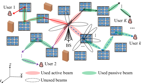
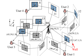
In this paper, we study this new MBMH routing problem for the downlink communication in a massive MIMO system, where a BS equipped with a large number of active antennas transmits independent messages to a set of remote single-antenna users simultaneously over the same frequency band, aided by multiple distributed IRSs as shown in Fig. 1. In [28], by considering only a single user in this system, we have derived the optimal single-beam multi-hop routing solution. However, different from [28], a new challenge arises in our considered MBMH routing design in this paper, which is to avoid the inter-user/path interference due to undesired scattering by the IRSs that serve for different users/paths, especially when there exist LoS channels between them. This thus leads to a new type of path separation constraints among different users, where the IRSs selected for different users/paths should avoid having LoS channels with each other. This stringent constraint thus makes the MBMH routing problem in this paper more challenging to solve, as compared to its single-beam special case in [28] without the inter-user/path interference considered. Moreover, unlike [1] and [28] where the continuous active/passive beamforming is assumed for the ease of exposition, in this paper we consider the more practical design based on beamforming codebook, which consists of only a finite number active/passive beamforming directions at the BS/IRSs, as shown in Fig. 1. This helps reduce the complexity of optimal beamforming design as well as hardware cost in general, especially for frequency division duplex (FDD) systems.
To solve the proposed MBMH routing problem in a multi-IRS aided massive MIMO network, we first derive the optimal BS/IRS active/passive beamforming solution in their respective codebooks for given beam-routing paths of the users, by exploiting the high angular resolution of the massive MIMO BS and the inter-IRS LoS channels, respectively. Next, we show that the resultant MBMH routing problem is NP-complete by recasting it into an equivalent neighbor-disjoint path optimization problem in graph theory. To deal with this challenging problem, a recursive algorithm is proposed to partially enumerate the feasible MBMH routing solutions. By tuning its parameter, the proposed algorithm can strike a flexible balance between performance and complexity. It is also shown that in the special case of continuous passive beamforming at the IRSs, the MBMH routing problem can be solved in a more efficient manner by the proposed algorithm. Numerical results show that our proposed algorithm can find the near-optimal MBMH routing solution with low computational complexity and outperforms other benchmark schemes. It is also revealed that the optimal MBMH routing solution varies considerably with the number of reflecting elements as well as the size of passive beamforming codebook at each IRS.
The rest of this paper is organized as follows. Section \@slowromancapii@ presents the system model. Section \@slowromancapiii@ presents the optimal BS/IRS active/passive beamforming design and the problem formulation for our considered MBMH routing optimization. Section \@slowromancapiv@ presents the proposed solution to this problem based on graph theory. Section \@slowromancapv@ presents the simulation results to show the performance of the proposed scheme as compared to other benchmark schemes. Finally, Section \@slowromancapvii@ concludes this paper and discusses future work.
The following notations are used in this paper. Bold symbols in capital letter and small letter denote matrices and vectors, respectively. The conjugate, transpose and conjugate transpose of a vector or matrix are denoted as , and , respectively. () denotes the set of real (complex) vectors of length . For a complex number , and denote its conjugate and amplitude, respectively. For a vector , denotes an diagonal matrix whose entries are given by the elements of ; while for a square matrix , denotes an vector that contains the diagonal elements of . denotes the Euclidean norm of the vector . denotes the greatest integer less than or equal to its argument. denotes the cardinality of a set . denotes the imaginary unit, i.e., . For two sets and , denotes the union of and . denotes an empty set. and denote the Hadamard product and Kronecker product, respectively. denotes the order of complexity. For ease of reference, the main symbols used in this paper are listed in Table I.
II System Model
As shown in Fig. 1, we consider a massive MIMO downlink system, where distributed IRSs are deployed to assist in the communications from a multi-antenna BS to remote single-antenna users. Assume that the BS is equipped with active antennas, while each IRS is equipped with passive reflecting elements. Without loss of generality and for ease of practical implementation, we assume that the BS serves the users by selecting beams from a predefined codebook, denoted as , which consists of orthogonal and unit-power beams, where can be arbitrarily large in massive MIMO. For the purpose of exposition, we consider the challenging scenario where the BS-user direct links are severely blocked for all the users considered in this paper. As such, the BS can only communicate with each user through a multi-reflection signal path that is formed by a set of IRSs associated with the user. To mitigate the potential inter-user interference during the multi-hop signal reflection, the signal paths for all users should be sufficiently separated and thus each IRS is associated with at most one user at one time, while it can serve multiple users over different time slots via proper user scheduling. As such, we focus on the MBMH routing design for a set of users in one given time slot. For convenience, we denote the sets of users and IRSs as and , respectively.
To maximize the reflected signal power by each selected IRS and ease the hardware implementation, we set the reflection amplitude of all its elements to the maximum value of one. As such, the reflection coefficient matrix of each IRS is given by , and its passive beamforming vector is denoted as . The passive beamforming vector of each IRS is assumed to be selected from a codebook , i.e., , and consists of beam patterns, where denotes the number of controlling bits for . For convenience, we refer to the BS and user as nodes 0 and in the system, respectively. Accordingly, we define as the channel from the BS to IRS , as that from IRS to user , and as that from IRS to IRS . For ease of exposition, we assume that the passive reflecting elements of each IRS in are arranged in a uniform rectangular array (URA) perpendicular to the ground and facing a fixed direction, while the BS employs a uniform linear array (ULA). For convenience, we apply a three-dimensional (3D) coordinate system locally at each IRS and assume that its URA is parallel to the - plane, as shown in Fig. 1. The antenna and element spacing at the BS and each IRS is assumed to be and , respectively. The numbers of elements in each IRS’s horizontal and vertical directions are assumed to be and , respectively, with .
Let denote the distance between nodes and , for which some reference transmitting/reflecting elements of the BS/IRSs are selected without loss of generality. To ensure the far-field propagation between any two nodes, we assume that , where denotes the minimum distance to satisfy this condition. According to [23], it must hold that , where denotes the carrier wavelength. Then, by carefully deploying the IRSs, LoS dominant propagation may be achieved between some pair of nodes and if is practically small (but larger than ). To simplify the active and passive beamforming designs as well as enhance the strength of the multi-reflection signal paths, we only exploit the LoS links in the system for the multi-hop signal reflection. Then, to describe the LoS condition between any two nodes (BS/IRS) and (IRS/user) in the considered system, we define a binary LoS condition indicator . In particular, indicates that the link between nodes and consists of an LoS link; otherwise, . In addition, we set and thus, .
Furthermore, each IRS can only achieve 180∘ half-space reflection, i.e., only the signal incident on its reflection side can be reflected, as shown in Fig. 1. Thus, for any two nodes and , if they are both IRSs, each of them needs to be located in the reflection half-space of the other to achieve effective signal reflection between them. For example, in Fig. 1, IRS and IRS cannot successively reflect the signal from the BS as they do not meet the above condition. Similarly, if one of the two nodes (say, node ) is the BS/user and the other node (say, node ) is an IRS, then node should be located in the reflection half-space of node . Equivalently, if the above conditions cannot be satisfied for any two nodes and , we can set . In this paper, to focus on the new MBMH routing design, we assume that the LoS condition indicators ’s are known and constant after deploying the IRSs, while how to acquire such knowledge in practice is an interesting problem to be addressed in our future work. Based on the LoS condition between any two nodes in the considered system, a multi-hop LoS link can be established between the BS and each user by properly selecting a subset of associated IRSs. For example, if , we can select IRSs and as the associated IRSs of user , which successively reflect its intended signal from the BS toward its receiver. For all IRSs that are not associated with any user in , the BS can inform their controllers can via the control links to turn them off based on its optimized MBMH routing solution, so as to minimize the scattered interference in the system.
Next, we characterize the LoS channel between any two nodes in the system (if any), which is modeled as the product of array responses at their two sides. For convenience, we define the following steering vector function,
| (1) |
where denotes the number of elements in a ULA, and denotes the phase difference between the observations at two adjacent elements. Obviously, is a periodic functions of and has a period of 2. Hence, we restrict in the sequel of this paper. If or , we set as . Then, the array response at the BS is expressed as
| (2) |
where denotes the angle-of-departure (AoD) relative to the BS antenna boresight. For the URA at each IRS, its array response is expressed as the Kronecker product of two steering vector functions in the horizontal and vertical directions, respectively, i.e.,
| (3) |
where and denote its elevation angle-of-arrival (AoA)/AoD and azimuth AoA/AoD, respectively. Then, we define as the AoD from the BS to IRS , / as the azimuth/elevation AoA at IRS from node (BS or IRS), and / as the azimuth/elevation AoD from IRS to node (IRS or user). The above AoAs and AoDs can be estimated by exploiting the geometric relationship of the BS, IRSs and users in the system[23] or by integrating sensors to the IRSs[3].
Based on the above, we define and for the LoS channel from the BS to IRS , and for that from IRS to IRS , as well as for that from IRS to user . Then, if , the BS-IRS channel is expressed as
| (4) |
where denotes the LoS path gain at the reference distance of 1 meter (m), and the exponential term captures the transmission delay over the LoS link. Similarly, if , the IRS -IRS channel is given by
| (5) |
Finally, if , the IRS -user channel is expressed as
| (6) |
Based on (4)-(6), we can characterize the multi-hop LoS channel between the BS and each user , with the given reflection path and BS/IRS active/passive beamforming. Specifically, let denote the reflection path from the BS to user , where and denote the number of associated IRSs for user and the index of the -th associated IRS, with , respectively. For convenience, we define and , corresponding to the BS and user , respectively. Then, to ensure that each IRS in only reflects user ’s information signal at most once, the following constraints should be met:
| (7) |
Moreover, each constituent link of , along with the BS-IRS link and the IRS -user link, should consist of an LoS link, i.e.,
| (8) |
Furthermore, to avoid the scattered inter-user interference, we consider that there is no direct LoS link111The methods and results in this paper are extendible to the more general path separation constraints, e.g., without -hop LoS link between any two reflection paths, with , by utilizing a similar approach as in Section IV-B. between any two nodes belonging to different reflection paths (except the common node or the BS). Thus, we have
| (9) |
Note that the condition ensures that there is no common node (except the BS) between any two different reflection paths and . As will be shown in Section V, the inter-user interference can be mitigated to a considerably lower level as compared to the information signal at each user ’s receiver thanks to the constraint (9).
Thus, each is a feasible path if and only if the constraints in (7)-(9) are satisfied. Given feasible paths , we define as the BS active beamforming design for user , with . Then, the BS-user effective channel is expressed as
| (10) |
which depends on both the CPB design for the selected IRSs and the active beamforming design for the BS. By substituting (4)-(6) into (10) and rearranging the terms in it, we obtain
| (11) |
where
| (12) |
is proportional to the end-to-end transmission distance, and
| (13) |
denotes the cascaded LoS path gain between the BS and user under the path , which turns out to be the product of the LoS path gains of all constituent links in . Note that the end-to-end delay under the path is equal to divided by the speed of light, which is thus negligible.
Thus, the equivalent channel gain between the BS and user , , is expressed as
| (14) |
Based on (14), we can obtain the optimal active/passive beamforming design at the BS/IRSs with a given MBMH routing solution, whereby the MBMH routing problem can be formulated, as detailed in the next section.
III Optimal Beamforming Design and Problem Formulation
In this section, we first derive the optimal active and passive beamforming design to maximize each in (14) under a given reflection path . With the optimal beamforming design, we then formulate the MBMH routing problem where only the reflection paths , need to be optimized.
III-A Optimal Active and Passive Beamforming Design
First, it is observed from (14) that for any given reflection path for user , to maximize , the magnitude of each and should be maximized, subject to the codebook constraints at each IRS and the BS, respectively. First, given the codebook at each IRS, consider that an IRS reflects the signal from its last node to the next node . We denote by its corresponding optimal passive beamforming vector, which can be obtained by enumerating all beam patterns in , i.e., ,222Similar passive beam search can also be performed in the case with mutual coupling among IRS elements, where the reflection coefficient matrix of each IRS is non-diagonal[29].
| (15) |
In particular, if the continuous passive beamforming with is applied at each IRS, as all array responses have unit-modulus entries, (15) can be simplified as
| (16) |
Accordingly, in the reflection path of user , the passive beamforming of each IRS should be set as
| (17) |
Note that in the special case of continuous IRS beamforming with , by substituting (16) and (17) into (12), we have .333For ease of exposition, we assume that a full amplitude gain of can be obtained in this paper, while it may be dependent on the incident and reflection angles at each IRS in practice.
To gain more useful insights into the optimal passive beamforming solutions at each IRS in (15) and (16), we consider that both nodes and are IRSs, which corresponds to the third case in (15). Then, according to (3), it can be shown that[30]
| (18) |
where and . Similarly, it can be verified that (18) also holds if node is the BS (the first case in (15)) or node is a user (the second case in (15)). It follows from (18) that if , the optimal passive beamforming in (16) can be rewritten as , which perfectly aligns the horizontal and vertical directions at the same time.
Motivated by this observation, we set in (18), where and denote the horizontal and vertical passive beamforming vectors for IRS , respectively. Then, we can obtain
| (19) |
It is noted from (19) that the passive beamforming of IRS can be decoupled into horizontal and vertical IRS passive beamforming. Accordingly, we define and as the codebooks for the horizontal and vertical IRS passive beamforming, respectively.444In the general case of multi-path channel model, a more sophisticated codebook structure may be needed. For example, in [31], an additional wavefront phase codebook is utilized to enable constructive or destructive superposition of the waves from different elements at the receivers. The numbers of controlling bits for and are denoted as and , respectively, which satisfy . Hence, the IRS codebook can be decomposed as
| (20) |
while the optimal IRS passive beamforming in (15) can be computed as , where
| (21) | ||||
| (22) |
Note that compared to the joint 3D beam search in (15), the complexity of beam search can be greatly reduced from to by separately solving (21) and (22). In particular, if node is not a user, i.e., , the above beam search for any triple nodes can be conducted offline, since the BS and all IRSs are fixed and their channels can be assumed to be constant over a long period.
Accordingly, in the reflection path of user , the passive beamforming of each IRS in (17) can be rewritten as
| (23) |
which can be simplified as
| (24) |
in the case of continuous passive beamforming at each IRS with .
Next, we focus on the optimal active beamforming design for the BS, which should maximize the amplitude of in (14). To this end, we define
| (25) |
as the optimal active beamforming solution for the BS to transmit the beam to IRS , which is obtained by enumerating all beam patterns in the codebook at the BS, , thus incurring the complexity of . Similar to the beam search in (21) and (22), the beam search in (25) can also be performed offline. In particular, if the continuous active beamforming is applied at the BS, (25) becomes equivalent to the maximum-ratio transmission (MRT) based on , i.e.,
| (26) |
With this definition, the BS active beamforming in the reflection path of user should be set as
| (27) |
where the effective phases of the reflection paths are compensated at the BS.
It is worth noting that if is sufficiently large, the MRT-based beamforming in (26) ensures that the power of the information signal for each user overwhelms that of the inter-user interference in the BS-IRS link, i.e., the first link in . This is because with a large , the BS antenna array has a practically high angular resolution. If all first-hop IRSs in the reflection paths for the users, i.e., IRS , are sufficiently separated in the angular domain, the following asymptotically favorable propagation for massive MIMO[32] can be achieved:
| (28) |
The asymptotically favorable propagation in (28) may also be achieved with practical finite-size codebooks, e.g., the discrete Fourier transform (DFT)-based codebook (see Section V for details). This is because when the codebook size is sufficiently large, the codebook will have a high resolution, such that the selected beam patterns are close to the MRT-based beamforming in (26). Hence, the inter-user interference can be approximately nulled in the first link of each reflection path by properly selecting . Furthermore, since the path separation constraints in (9) ensure that the scattered inter-user interference in the subsequent links of is well mitigated, user is approximately free of inter-user interference, while achieving the maximum end-to-end channel gain with the BS via IRSs’ passive beamforming in (III-A) and the BS’s active beamforming in (27).
Under the above optimal beamforming designs, we define as the maximum value of in (12) by following (III-A). It is worth noting that depends on the AoAs/AoDs between nodes and , as well as those between nodes and . Besides, it also depends on the numbers of controlling bits for the IRS codebooks, i.e., and . In particular, with increasing or , the resolution of IRS codebook can be improved, thus resulting in a larger . In the special case of continuous IRS beamforming with , we have , which is regardless of the AoAs/AoDs. It follows that the effect of AoAs and AoDs diminishes when the resolution of IRS codebooks becomes higher. By substituting (III-A) and (28) into (14), the maximum BS-user equivalent channel gain is given by
| (29) |
It is observed from (29) that besides the conventional active BS beamforming gain of , a new multiplicative CPB gain of is also achieved for each BS-user equivalent channel. As previously discussed, if or is small, this multiplicative CPB gain will depend heavily on the AoAs and AoDs between any two consecutive nodes in . However, if both and are sufficiently large, this CPB gain can be greatly enhanced and approaches its maximum value, . In general, there exists a fundamental trade-off between maximizing the CPB gain versus the end-to-end path gain, i.e., in (13) (or minimizing the end-to-end path loss ), as the former monotonically increases with , while the latter generally decreases with . Besides this trade-off, there exists another trade-off in balancing all ’s for different users in . Specifically, due to the practically finite number of IRSs and LoS paths in the system as well as the path separation constraints in (9), maximizing the channel gain for one user generally reduces the number of feasible paths for the other users. Particularly, if the number of users is large, some users may be denied access due to the lack of feasible paths. As such, the optimal MBMH routing design should reconcile the above trade-offs and take into account the resolution of practical IRS codebooks, so as to achieve the optimum performance of all users in a fair manner.
It should be mentioned that in addition to the reflection path , there may also exist some other signal paths between the BS and user due to the random scattering of all active IRSs in the system. Nonetheless, as will be shown in Section V, the strength of these scattered links is practically much lower than that of in (29), due to the lack of joint active and CPB gains over these scattered links. As such, we only focus on the multi-reflection path in this paper.
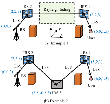
Numerical Example: To better manifest the benefits of the proposed multi-IRS aided system, we provide the following two numerical examples, as shown in Fig. 3. In Example 1, as shown in Fig. 3(a), there are two IRSs (labelled as 1 and 2) deployed near the user and BS, respectively, such that LoS-dominant channels can be achieved between the BS and IRS 2 as well as between the user and IRS 1. However, due to the scattered obstacles in the environment, IRS 1 cannot establish an LoS-dominant channel with IRS 2. Accordingly, we assume Rayleigh fading for the channel between them, with a path-loss exponent denoted by . In Example 2, as shown in Fig. 3(b), an additional IRS 3 is properly deployed such that LoS-dominant channels can be established between it and both IRSs 1 and 2. For convenience, in both examples, we assume that each IRS and the BS employ continuous passive and active beamforming, respectively. Moreover, we follow the notations in the previous sections and refer to the BS and user as nodes 0 and 4, respectively. As such, based on (26), the optimal BS beamforming is given by the MRT in both examples. Furthermore, in Example 2, based on (16), the optimal passive beamforming vectors of IRSs 1, 2, and 3 are given by , , and , respectively. However, it is generally difficult to derive the optimal passive beamforming vectors of IRSs 1 and 2 in Example 1 due to the arbitrary-rank channel between them. In this paper, we apply a similar alternating optimization approach as in [26] to alternately optimize the passive beamforming of one IRS with that of the other being fixed, until convergence is reached.
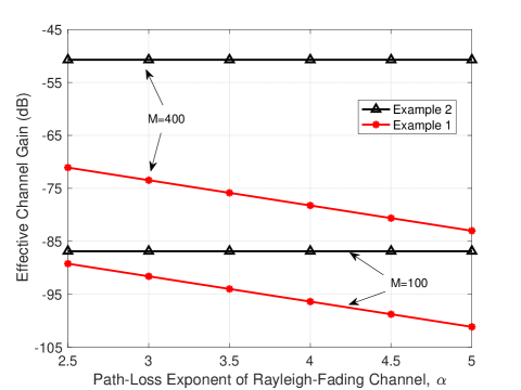
In Fig. 3, we plot the effective BS-user channel gain in Example 1 versus the path-loss exponent of the Rayleigh-fading channel between IRSs 1 and 2, , and compare it with that in Example 2. The BS is equipped with antennas, while each IRS is equipped with or reflecting elements. The carrier frequency is set to 5 GHz. All results are averaged over 100 random channel realizations. It is observed from Fig. 3 that the effective BS-user channel gain in Example 1 monotonically decreases with and is lower than that in Example 2. In particular, when , it is around 20 dB lower than that in Example 2 even for . This is expected since no CPB gain can be achieved in Example 1 while a significant CPB gain of can be achieved in Example 2 despite its generally higher end-to-end path loss. Thus, the proposed multi-IRS aided system is practically useful in enhancing the communication link strength in a complex environment with dense obstacles.
III-B Problem Formulation
In this paper, we aim to maximize the minimum signal-to-noise-plus-interference ratio (SINR) achievable by the users, by optimizing the reflection paths , subject to the feasibility constraints in (7)-(9). Due to the well mitigated inter-user interference at each user’s receiver, this is equivalent to maximizing the minimum BS-user effective channel gain, i.e., . The optimization problem is thus formulated as
| (30) |
However, (P1) is a combinatorial optimization problem due to its integer and coupled variables. In addition, in are functions of the corresponding AoAs and AoDs if or is finite, while they become a constant in the case of continuous IRS beamforming, as considered in [1] and [28]. Thus, it is challenging to obtain the optimal solution to (P1) via standard optimization methods in general, especially in the case with a small or . To tackle this challenging problem, we reformulate it as an equivalent graph-optimization problem which is then solved, as detailed in the next section.
IV Proposed Solution to (P1)
In this section, we first reformulate (P1) as an equivalent problem in graph theory under the general case with finite and , and thereby show that it is NP-complete. Then, a parametrized recursive algorithm is proposed to efficiently solve this problem sub-optimally in general. Finally, we show that (P1) can be more efficiently solved by the proposed algorithm in the special case of continuous IRS beamforming with and .
IV-A Problem Reformulation via Graph Theory
Obviously, in (P1), it is equivalent to minimizing the maximum among all . Based on (14), we have
| (31) |
Next, we recast problem (32) as an equivalent problem in graph theory subject to the constraints (7)-(9). Following the similar procedures in [1] and [28], we construct a directed and unweighted graph . The vertex set consists of all nodes in the system, i.e., . Furthermore, we consider that each of the beams can only be routed outwards from one IRS to a farther IRS from the BS with , so as to reach its intended user as quickly as possible. Hence, the edge set is defined as
| (34) |
i.e., there exists an edge from vertex to vertex if and only if an LoS path exists between them and , except that vertex corresponds to a user, i.e., . Thus, we have . Note that (34) ensures that there is no circle in , i.e., is a direct acyclic graph (DAG). Given the constructed graph , any reflection path from the BS to user corresponds to a path from node 0 to node in . However, different from the beam routing problems in [1] and [28] with continuous IRS beamforming with and , it is difficult to assign a weight to each edge in to recast problem (32) as an equivalent graph-optimization problem. This is because each in (33) is associated with three vertices, i.e., vertices , and , but each edge in is only associated with two vertices. However, in [1] and [28], we have , which greatly simplifies the weight assignment in .
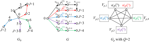
To resolve the above issues, a new DAG of higher dimension, denoted as , should be constructed from . Specifically, besides vertex and vertices , we create a vertex in for each edge in ; while for every two edges in that share a common vertex, we create an edge between their corresponding vertices in . The resulting graph is known as the line graph of in graph theory. Mathematically, for , its vertex set is given by
| (35) |
Obviously, we have . The edge set is given by
| (36) |
It follows from (35) and (36) that the edge () indicates that there exists an LoS path from the BS (IRS ) to IRS (user ). Moreover, the edge indicates that there exist two pairwise LoS paths from node and node via IRS . In this new graph , some edges in involve three vertices, thus making the weight assignment possible. To determine the edge weights in , we first rewrite in (33) as
| (37) |
by rearranging the terms in it. Accordingly, the weight of each edge in is set as follows:
| (38) |
Note that the above weights may be negative, e.g., when , and are practically large, such that the argument of the logarithm in (38) is smaller than one.
With the constructed line graph , we can establish a one-to-one correspondence between each path from vertex to vertex in and that in . For example, if a path in is given by , then it corresponds to the path in and thus a reflection path from the BS to user 1 via IRSs 1 and 3. In particular, the sum of edge weights of any path from vertex to vertex in is equal to , if its corresponding path in is . Since is a DAG, it is easy to verify that is also a DAG. Thus, for any path in , its corresponding path in can automatically satisfy the constraints in (7)-(8). To handle the more challenging constraint (9), we present the following definitions.
Definition 1
Neighbor-disjoint paths refer to the paths in a graph which do not have any common or neighboring vertices except their starting points.
According to Definition 1, the constraints in (9) can be satisfied if the paths from vertex to vertices in are neighbor-disjoint. As such, problem (32) is equivalent to the following graph-optimization problem, denoted as (P2).
Note that neighbor-disjoint routing design has been previously studied in various multi-hop wireless networks, such as ad-hoc networks and wireless sensor networks, for the purpose of load balancing or interference mitigation[33, 34]. However, most of these works only focus on discovering a set of neighbor-disjoint paths through different medium access control (MAC) layer protocols, but not from an optimal routing design perspective. A common routing design is by utilizing the shortest path algorithm to sequentially update the paths for the users[33]. Specifically, after deriving the shortest path for a user in , the nodes in its corresponding path in (except node 0) and their neighbors are removed. Then, a new line graph is constructed to determine the shortest path for the next user, so as to satisfy (9). However, as will be shown in Section V, this sequential update design generally yields suboptimal paths and even fails to return feasible paths. This is because the set of feasible paths for the current user critically depends on the previously optimized paths for the other users. In fact, it has been proved in [34] that finding neighbor-disjoint paths in is NP-complete even in the case of . As such, (P2) remains a challenging problem, which will be solved next.
IV-B Proposed Solution to (P2)
The basic idea of the proposed solution to (P2) is by first finding candidate shortest paths from node 0 to each node in (thus ). Given these candidate shortest paths, we further construct a new path graph, based on which a recursive algorithm is performed to partially enumerate the feasible paths and select the best one as the solution to (P2), as specified below.
1) Step 1: Find the candidate shortest paths. First, for the nodes 0 and in , we invoke the Yen’s algorithm[35] to find candidate shortest paths between them. If the total number of paths between the two nodes is less than , we assume that there exist additional virtual paths between them with infinite sum of edge weights. For convenience, we denote by and the -th candidate shortest path between vertices 0 and and its sum of edge weights, respectively. Let be the set of all candidate shortest paths. The time complexity for this step is [35].
2) Step 2: Construct the path graph. Next, we construct a new undirected graph , where each vertex in corresponds to one candidate shortest path obtained in Step 1 (thus termed as path graph), i.e., . Hence, we have . By this means, we can establish a one-to-one mapping between any path in and one vertex in . Moreover, since there also exists a one-to-one mapping between any path in (thus in ) and a path in , each vertex in also corresponds to a unique path in . In particular, the vertex in corresponds to a path from vertex 0 to vertex in . For example, as shown in Fig. 4, if the path is the second candidate shortest path from node 0 to node in and also included in (e.g., ), then it corresponds to the vertex in , which thus corresponds to the path in . Based on this fact, for any two vertices in , we add an edge between them if and only if their corresponding paths in are neighbor-disjoint or satisfy the considered path separation constraints. As , we need to execute this procedure times; while in each execution, we need to check the connectivity between any two vertices in the two corresponding paths in , respectively, so as to determine whether they are neighbor-disjoint or not. Since the number of vertices in any path in should not exceed , the worst-case complexity of this step is given by . Finally, we assign each vertex in with a weight, which is equal to the sum of edge weights of its corresponding path in , i.e., , obtained in Step 1.
To relate the path graph to (P2), we first introduce the following definitions.
Definition 2
A -partite graph refers to a graph whose vertices can be partitioned into disjoint sets, such that there is no edge between any two vertices within the same set.
Definition 3
A clique is a subset of vertices of an undirected graph, such that every two distinct vertices in the clique are adjacent.
Based on Definitions 2 and 3, we can verify the following facts, which specify the relationship among , and .
Fact 1
is a -partite graph, with the -th disjoint set given by .
Fact 2
For neighbor-disjoint paths from vertex 0 to vertices in , if their corresponding paths in are included in , they correspond to a clique of size in .
Fact 1 can be proved by noting that for any two vertices in each , their corresponding paths in should not be neighbor-disjoint, since they share the same end vertex . For Fact 2, it can be easily verified based on Definition 3 and the definition of . For example, in Fig. 4, is a 4-partite graph and consists of two cliques of size 4, i.e., and , each corresponding to 4 neighbor-disjoint paths in . The two vertices and in are not connected as their corresponding paths in share the same end vertex .
According to Facts 1 and 2, we aim to solve the following clique search problem, denoted as (P3).
The optimal clique for (P3) corresponds to the best solution to (P2) among the paths in . Thus, if is set to be sufficiently large, such that the optimal paths from node 0 to each node are included in , the proposed algorithm ensures to find an optimal solution to (P2) (and hence (P1)), if (P3) is optimally solved. Accordingly, by tuning the value of its parameter , the proposed algorithm can flexibly balance between its performance and complexity.
3) Step 3: Clique enumeration. To find the optimal solution to (P3), we can enumerate all cliques of size in and then compare their respective maximum vertex weights. However, finding all cliques of size in a graph is also an NP-complete problem in general when [35]. As such, we propose a recursive algorithm to achieve this purpose by leveraging the -partite property of , thereby optimally solving (P3).
Specifically, we will show that each clique of size in can be recursively constructed based on the cliques of smaller sizes. Note that its vertices must be selected from the disjoint sets , respectively. Without loss of optimality, we assume that its -th vertex is selected from . Accordingly, let denote the set of all cliques of size in , with the -th vertex of each clique in selected from . Obviously, we have . Moreover, for each clique (of size ) in , if there exists a vertex in which is adjacent to all vertices in this clique, then a new clique (of size ) in can be constructed by appending the vertex to this clique. As such, based on the initial condition for and the recursion for , all cliques of size in can be enumerated in the set , which requires the worst-case complexity of . To further reduce complexity, it is noted that when a clique of size is constructed, among all feasible vertices in , we only need to append the vertex with the lowest weight to it. This is because the cliques obtained by appending other feasible vertices cannot yield a lower maximum vertex weight. Thus, the worst-case complexity of the above recursive algorithm can be reduced to . In fact, since the number of feasible vertices may significantly decrease when increasingly larger cliques are constructed (owing to the more stringent adjacency constraint), the actual complexity of the proposed recursive enumeration is much lower than , as will be shown in Section V.
Denote by the -th clique (of size ) in after the enumeration. For each , we can obtain the maximum vertex weight among all of its vertices, denoted as
Thus, the best clique in can be obtained as , with . The main procedures of the proposed clique enumeration method for solving (P3) are summarized in Algorithm 1, where a function “RecEnum” is defined and recursively called to achieve the recursive enumeration.
4) Step 4: Map and output. Finally, a generally suboptimal MBMH routing solution with a finite value of can be obtained by mapping the vertices in to neighbor-disjoint paths in . The process of solving (P2) is summarized in Algorithm 2. The worst-case complexity of Algorithm 2 is given by the sum of the complexity of the first three steps, i.e., . Since the active beam search in (25) and the passive beam search in (21) and (22) with can be conducted offline, the online complexity of the proposed MBMH routing design is given by the sum of the complexity of Algorithm 2 and that of the passive beam search for the users at their associated final-hop IRSs.
It is worth noting that if with a given after performing Algorithm 1, this indicates that (P3) is infeasible. To obtain a feasible clique of size , the value of can be increased to enlarge the solution set of (P3). However, if (P3) is still infeasible even with the maximum allowable , then it can be claimed that (P2) (thus (P1)) is infeasible. As such, some users would be denied access to the considered system. This may happen if the number of users is large (e.g., ) or some users are close to each other, such that the path separation constraints cannot be met. Besides, if the number of IRSs is small or they are not properly deployed, (P2) may also be infeasible due to the limited number of reflection paths. In this case, the proposed algorithms can help determine the optimal user selection and the reflection paths for the selected users. Specifically, let be the maximum number of users that can be granted access to the considered system, which is given by the maximum value of such that . Then, the selected users and their reflection paths can be obtained by mapping the best clique (of size ) in to neighbor-disjoint paths in .
IV-C Special Case with Continuous IRS Beamforming
If the continuous beamforming with and is applied at each IRS, (P1) can be more efficiently solved based on , without the need of constructing its line graph . Specifically, since we have in this case, (31) becomes
| (39) |
By taking the logarithm of (39) and discarding irrelevant constant terms therein, (P1) becomes equivalent to
| (40) |
Similarly as in Section IV-A, we construct the DAG . However, according to (40), we can directly assign a weight to each edge in , denoted as . As a result, (P2) reduces to finding neighbor-disjoint paths from vertex to vertices in , respectively, such that the length of the longest path is minimized. To solve this simplified problem, Algorithm 2 can be similarly applied. The only difference is that the input graph is instead of .
V Numerical Results
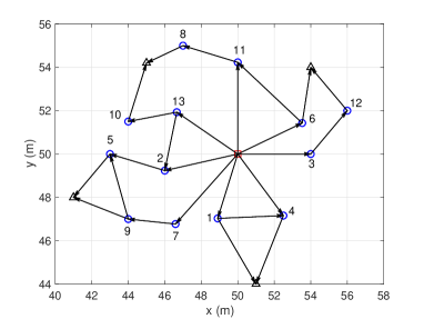
In this section, we provide numerical results to evaluate our proposed MBMH routing design. We focus on an indoor multi-IRS aided system (e.g., in a smart factory) with users and IRSs. The 3D coordinates of all nodes, their available LoS links, as well as the facing directions of all IRSs are shown in Fig. 5(a). The system is assumed to operate at a carrier frequency of 5 GHz. Thus, the carrier wavelength is m and the LoS path gain at the reference distance 1 m is dB. Based on the LoS probability specified in [36], for any two nodes and that satisfy the facing condition, we consider that there is an LoS-dominant link between them, i.e., , if its occurrence probability is equal to one, or 5 m. Whereas if , we assume that there exist rich scatterers between nodes and and model their channel as Rayleigh fading with a path-loss exponent of . The antenna and element spacing at the BS and each IRS are set to and , respectively. Moreover, we set the minimum distance for far-field propagation as 2.5 m. Accordingly, the graph representation of the considered multi-IRS aided system, i.e., , is shown in Fig. 5(b). The numbers of elements in each IRS’s horizontal and vertical dimensions are set to be identical as . The BS is equipped with antennas. We use the -point DFT-based codebook as the BS’s codebook , which equally divides the spatial domain into sectors. Specifically, let denote the -th beam pattern in . We have
| (41) |
It is verified via simulation that with the deployment of IRSs in Fig. 5 and the codebook in (41), the asymptotically favorable propagation in (28) can be achieved for all links between the BS (node 0) and the possible first-hop IRSs (the neighbors of node 0 in ). The numbers of controlling bits for each IRS’s codebooks in the horizontal and vertical dimensions, i.e., and , are assumed to be identical as . Thus, the number of beam patterns in and is identical to . Similarly as the BS, the -point DFT codebook is used for and , while the proposed MBMH routing design is applicable to any IRS beamforming codebook. Let and denote the -th beam patterns in and , respectively. Then, we have
| (42) |
In the proposed recursive algorithm, the number of candidate shortest paths for each node or user is set to .
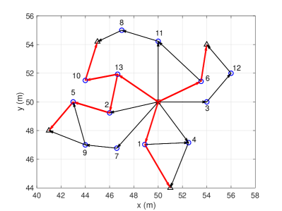
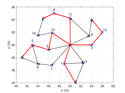
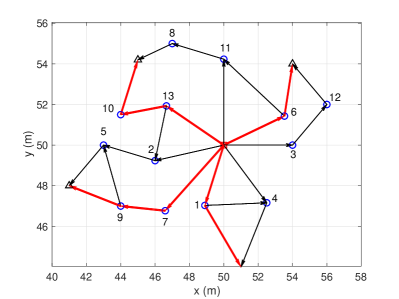
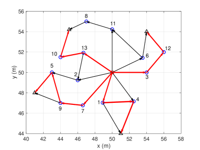
First, Fig. 6 shows the optimized reflection paths for all users under different numbers of IRS reflecting elements and controlling bits for the IRS codebook in each dimension, i.e., and . In Fig. 6(a), by utilizing the Bellman-Ford algorithm[35] for the shortest path problem on , we plot the optimal reflection path for each user without the path separation constraints in (9) under (i.e., ) and (i.e., ) bits. It is observed that IRS 13 exists in the reflection paths for both users 3 and 4. Thus, the proposed algorithm is needed to obtain a feasible MBMH routing solution to (P1) that meets (9). In Figs. 6(b)- 6(d), we plot the optimized MBMH routing solutions by the proposed algorithm subject to (9). By comparing Fig. 6(b) with Fig. 6(a), it is observed that the paths for users 2 and 4 are changed due to the path separation constraints in (9). As a result, their effective channel gains with the BS are sacrificed in order to yield neighbor-disjoint paths between the BS and all users. On the other hand, by comparing Fig. 6(b) with Fig. 6(c), it is observed that for a given , increasing the resolution of the IRS codebook may lead to different optimized paths. This is expected since with a larger , each IRS has a higher degree of freedom in controlling the direction of the reflected signal, which may result in different reflection paths. Next, by comparing Fig. 6(b) with Fig. 6(d), it is observed that when , the optimized paths for some users, e.g., user 1, may go through more IRSs under than those under . This is due to the different dominating effects of the end-to-end path loss and the CPB gain in maximizing the users’ effective channel gains with the BS as becomes large. In particular, as , minimizing the end-to-end path loss is dominant over maximizing the CPB gain. However, as increases to , maximizing the CPB gain becomes more dominant. Since the CPB gain monotonically increases with the hop count of the reflection path when is large, the optimized reflection paths generally go through more IRSs.
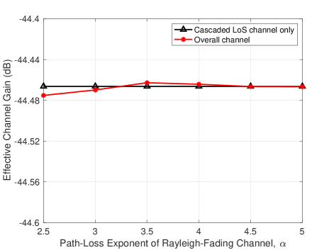
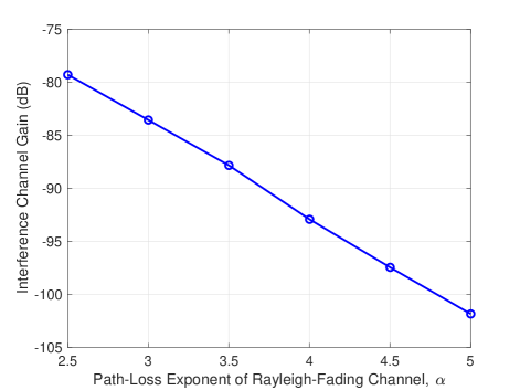
To measure the strength of the scattered links in the system, under the optimized MBMH routing solution in Fig. 6(b), we plot in Fig. 8 the power of the overall channel between the BS and user 4, i.e., the cascaded LoS channel via IRSs 8 and 11 (or ) plus other scattered channels by active IRSs in the system, versus the path-loss exponent of Rayleigh-fading channels, . As there are two hops in , we only consider all single-hop and double-hop scattered links between the BS and user 4, due to the more severe multiplicative path-loss and lack of CPB gain over other multi-hop scattered links. The results are averaged over 100 channel realizations. It is observed from Fig. 8 that the overall channel gain is comparable to the cascaded LoS channel gain over the whole range of considered. This indicates that the strength of the scattered links in the system is practically much lower than that of and thus can be ignored. Furthermore, to evaluate the performance of the proposed algorithm in terms of mitigating the inter-path interference, we plot in Fig. 8 the total interference channel gain between the BS and user 4 for serving the other three users. By comparing Fig. 8 with Fig. 8, it is observed that even with , the strength of the interfering links is about 35.5 dB lower than that of . As increases, the former further decreases and becomes around 57.5 dB lower than the latter with . Given a common signal-to-noise ratio (SNR) level between 20 and 30 dB in modern data transmission, the inter-user interference has been well suppressed below the receiver noise (including other non-IRS reflected interference) in the considered system.
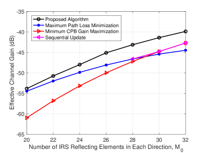
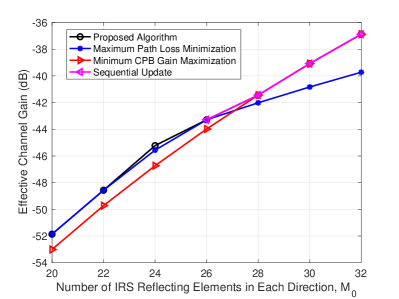
Next, Fig. 9 shows the max-min BS-user channel gain among all users by different schemes versus the number of IRS reflecting elements in each dimension, , under and . For performance comparison, we consider the following three benchmark schemes. The first benchmark is the sequential update scheme, as mentioned at the end of Section IV-A, where we sequentially update the reflection paths from user 1 to user 4. The second benchmark minimizes the maximum path loss among all BS-user LoS links, while the third benchmark maximizes the minimum CPB gain among all BS-user LoS links. Their corresponding reflection paths can be obtained by assuming unit CPB gain and unit end-to-end path loss, i.e., and , in our proposed algorithm, respectively.
First, it is observed from Fig. 9(a) that when or the resolution of the IRS codebook is low, all benchmarks are observed to achieve a much worse performance as compared to the proposed algorithm. The sequential update scheme even fails to output feasible paths when . This is because its performance critically depends on the order of the update for the users. In addition, the second benchmark fails to take into account the effect of AoAs and AoDs in the network when is small, as discussed at the end of Section III-A; while the third benchmark overestimates the effect of CPB gain and overlooks that of end-to-end path loss. On the other hand, as increases to , the second and third benchmarks are observed to achieve the comparable performance as the proposed algorithm when and , respectively. This is because the CPB gain is greatly improved with increasing and the effect of AoAs and AoDs diminishes. As such, the CPB gain and end-to-end path loss can dominate the BS-user effective channel gain when is large and small, respectively. However, when , these two schemes are observed to yield worse performance than the proposed algorithm, which strikes a better trade-off between maximizing the CPB gain and minimizing the end-to-end path loss.
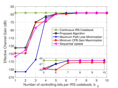
Finally, in Fig. 10, we plot the max-min BS-user channel gain by the proposed algorithm and the above three benchmark schemes versus the number of controlling bits for IRS codebook in each dimension, , under . In addition, we also show the performance by the continuous IRS beamforming with . It is observed that the continuous IRS beamforming yields the largest max-min BS-user channel gain among all schemes considered. This is because the maximum passive beamforming gain can be achieved at each selected IRS for any given reflection paths, i.e., . Nonetheless, as increases, it is observed that the performance of the proposed algorithm improves and eventually achieves a performance very close to the continuous IRS beamforming as . In contrast, the sequential update scheme is observed to achieve a worse performance than our proposed algorithm as and fails to output feasible paths when . Although the second benchmark yields the same performance as our proposed algorithm when , its performance becomes worse than ours when decreases. The reason is that it fails to consider the effect of AoAs and AoDs in the network as is small. The third benchmark is observed to achieve a worse performance than our proposed algorithm, since it overlooks the end-to-end path loss. However, it outperforms the second benchmark when . This indicates that the AoAs and AoDs in the network or the placement of IRSs may be more dominant than the end-to-end path-loss when is extremely small. All the above observations are consonant with our analysis provided at the end of Section III-A.
VI Conclusions
This papers studies a new MBMH routing problem for a multi-IRS aided massive MIMO system, where cascaded LoS links are established between the multi-antenna BS and multiple users by exploiting the cooperative signal reflections of selected IRSs. We present the optimal active and passive beamforming solutions at the BS and each selected IRS, respectively. However, under the stringent path separation constraints for avoiding the inter-user interference, the MBMH routing problem is NP-complete and challenging to solve. To derive a high-quality suboptimal solution without incurring prohibitive complexity, we propose a parameterized recursive algorithm for this problem by leveraging graph theory. It is shown that both the number of IRS reflecting elements and size of IRS beamforming codebook can greatly impact the optimal MBMH routing solution as well as the achievable max-min BS-user channel gain. In particular, the optimal MBMH routing design should take into account the AoAs and AoDs in the system if the size/resolution of IRS beamforming codebook is not large. Besides, there exists a fundamental trade-off between minimizing the end-to-end path loss and maximizing the CPB gain, which have different dominating effects under different numbers of IRS reflecting elements.
This paper can be extended in several promising directions for future work, some of which are listed as follows to motivate future works.
-
•
First, it is interesting to study the MBMH routing problem under the general multi-path channel model. In this case, the MBMH routing problem becomes more challenging to be solved as the beamforming design cannot be simplified by assuming the LoS inter-IRS channels. In a parallel work[37], the authors applied a deep reinforcement learning (DRL) approach to optimize the BS/IRS active/passive beamforming, under a given reflection path. As such, it is worthy of further investigating new approaches for the joint beamforming and MBMH routing design under the general multi-path channel model. Moreover, how to find an efficient approach without assuming any prior channel knowledge is challenging.
-
•
Second, the considered MBMH routing problem may become infeasible as the number of users is large or some users are close to each other in location. In this case, each IRS may be associated with more than one user to aid their transmission over orthogonal time slots or simultaneous transmission over orthogonal frequency resource blocks (RBs). In the latter case, each IRS can split its elements into multiple sub-surfaces (or co-located smaller IRSs equivalently), each associated with one user by reflecting the signal in its corresponding frequency band. As such, under any RB allocation scheme, our proposed MBMH routing design can be extended to this setup by treating the random scattering by co-located IRSs as part of environment scattering and applying our proposed path separation constraint to those IRSs reflecting user signals over the same frequency band. However, in both the cases above, user scheduling/RB allocation and IRS beam routing/passive reflection need to be jointly designed, which is interesting to study in future work.
-
•
Third, as our main focus is on the new MBMH routing design, we consider a simplified IRS model in this paper, while a more accurate model may be needed in practical routing design to account for other aspects pertaining to electromagnetic propagation and device hardware imperfections, such as mutual coupling among IRS elements[29], angle-dependent passive beamforming gain[31], near-field effects[38], etc. Nonetheless, the proposed algorithm provides a theoretical bound for the performance of practical MBMH routing designs, which can be calibrated by properly introducing correction factors to account for hardware effects by adjusting the weights in the constructed graphs accordingly.
References
- [1] W. Mei and R. Zhang, “Cooperative multi-beam routing for multi-IRS aided massive MIMO,” in Proc. IEEE Int. Conf. Commun., Montreal, Canada, Jun. 2021.
- [2] Q. Wu and R. Zhang, “Towards smart and reconfigurable environment: Intelligent reflecting surface aided wireless network,” IEEE Commun. Mag., vol. 58, no. 1, pp. 106–112, Jan. 2020.
- [3] Q. Wu, S. Zhang, B. Zheng, C. You, and R. Zhang, “Intelligent reflecting surface aided wireless communications: A tutorial,” IEEE Trans. Commun., vol. 69, no. 5, pp. 3313–3351, May 2021.
- [4] E. Basar et al., “Wireless communications through reconfigurable intelligent surfaces,” IEEE Access, vol. 7, pp. 116 753–116 773, Sep. 2019.
- [5] Q. Wu and R. Zhang, “Intelligent reflecting surface enhanced wireless network via joint active and passive beamforming,” IEEE Trans. Wireless Commun., vol. 18, no. 11, pp. 5394–5409, Nov. 2019.
- [6] S. Zhang and R. Zhang, “Capacity characterization for intelligent reflecting surface aided MIMO communication,” IEEE J. Sel. Areas Commun., vol. 38, no. 8, pp. 1823–1838, Aug. 2020.
- [7] V. Jamali, A. M. Tulino, G. Fischer, R. R. Müller, and R. Schober, “Intelligent surface-aided transmitter architectures for millimeter-wave ultra massive MIMO systems,” IEEE Open J. Commun. Soc., vol. 2, pp. 144–167, 2020.
- [8] K. Zhi, C. Pan, H. Ren, and K. Wang, “Statistical CSI-based design for reconfigurable intelligent surface-aided massive MIMO systems with direct links,” IEEE Wireless Commun. Lett., vol. 10, no. 5, pp. 1128–1132, May 2021.
- [9] Y. Yang, B. Zheng, S. Zhang, and R. Zhang, “Intelligent reflecting surface meets OFDM: Protocol design and rate maximization,” IEEE Trans. Commun., vol. 68, no. 7, pp. 4522–4535, Jul. 2020.
- [10] Y. Yang, S. Zhang, and R. Zhang, “IRS-enhanced OFDMA: Joint resource allocation and passive beamforming optimization,” IEEE Wireless Commun. Lett., vol. 9, no. 6, pp. 760–764, Jun. 2020.
- [11] B. Zheng, Q. Wu, and R. Zhang, “Intelligent reflecting surface-assisted multiple access with user pairing: NOMA or OMA?” IEEE Commun. Lett., vol. 24, no. 4, pp. 753–757, Apr. 2020.
- [12] T. Hou, Y. Liu, Z. Song, X. Sun, Y. Chen, and L. Hanzo, “Reconfigurable intelligent surface aided NOMA networks,” IEEE J. Sel. Areas Commun., vol. 38, no. 11, pp. 2575–2588, Nov. 2020.
- [13] C. Pan, H. Ren, K. Wang, W. Xu, M. Elkashlan, A. Nallanathan, and L. Hanzo, “Multicell MIMO communications relying on intelligent reflecting surfaces,” IEEE Trans. Wireless Commun., vol. 19, no. 8, pp. 5218–5233, Jun. 2020.
- [14] W. Mei and R. Zhang, “Performance analysis and user association optimization for wireless network aided by multiple intelligent reflecting surfaces,” IEEE Trans. Commun., 2021, early access, doi: 10.1109/TCOMM.2021.3087620.
- [15] Q. Wu and R. Zhang, “Joint active and passive beamforming optimization for intelligent reflecting surface assisted SWIPT under QoS constraints,” IEEE J. Sel. Areas Commun., vol. 38, no. 8, pp. 1735–1748, Aug. 2020.
- [16] C. Pan, H. Ren, K. Wang, M. Elkashlan, A. Nallanathan, J. Wang, and L. Hanzo, “Intelligent reflecting surface aided MIMO broadcasting for simultaneous wireless information and power transfer,” IEEE J. Sel. Areas Commun., vol. 38, no. 8, pp. 1719–1734, Aug. 2020.
- [17] T. Jiang and Y. Shi, “Over-the-air computation via intelligent reflecting surfaces,” in Proc. IEEE Global Commun. Conf., Waikoloa, HI, USA, Dec. 2019.
- [18] T. Bai, C. Pan, Y. Deng, M. Elkashlan, A. Nallanathan, and L. Hanzo, “Latency minimization for intelligent reflecting surface aided mobile edge computing,” IEEE J. Sel. Areas Commun., vol. 38, no. 11, pp. 2666–2682, Nov. 2020.
- [19] M. Cui, G. Zhang, and R. Zhang, “Secure wireless communication via intelligent reflecting surface,” IEEE Wireless Commun. Lett., vol. 8, no. 5, pp. 1410–1414, Oct. 2019.
- [20] X. Yu, D. Xu, Y. Sun, D. W. K. Ng, and R. Schober, “Robust and secure wireless communications via intelligent reflecting surfaces,” IEEE J. Sel. Areas Commun., vol. 38, no. 11, pp. 2637–2652, Nov. 2020.
- [21] H. Lu, Y. Zeng, S. Jin, and R. Zhang, “Enabling panoramic full-angle reflection via aerial intelligent reflecting surface,” in Proc. IEEE Int. Conf. Commun. Workshop, Dublin, Ireland, Jun. 2020.
- [22] S. Fang, G. Chen, and Y. Li, “Joint optimization for secure intelligent reflecting surface assisted UAV networks,” IEEE Wireless Commun. Lett., vol. 10, no. 2, pp. 276–280, Feb. 2021.
- [23] Y. Han, S. Zhang, L. Duan, and R. Zhang, “Cooperative double-IRS aided communication: Beamforming design and power scaling,” IEEE Wireless Commun. Lett., vol. 9, no. 8, pp. 1206–1210, Aug. 2020.
- [24] C. You, B. Zheng, and R. Zhang, “Wireless communication via double IRS: Channel estimation and passive beamforming designs,” IEEE Wireless Commun. Lett., vol. 10, no. 2, pp. 431–435, Feb. 2021.
- [25] B. Zheng, C. You, and R. Zhang, “Efficient channel estimation for double-IRS aided multi-user MIMO system,” IEEE Trans. Commun., vol. 69, no. 6, pp. 3818–3832, Jun. 2021.
- [26] B. Zheng, C. You, and R. Zhang, “Double-IRS assisted multi-user MIMO: Cooperative passive beamforming design,” IEEE Trans. Wireless Commun., 2021, early access.
- [27] L. Dong, H.-M. Wang, J. Bai, and H. Xiao, “Double intelligent reflecting surface for secure transmission with inter-surface signal reflection,” IEEE Trans. Veh. Technol., vol. 70, no. 3, pp. 2912–2916, Mar. 2021.
- [28] W. Mei and R. Zhang, “Cooperative beam routing for multi-IRS aided communication,” IEEE Wireless Commun. Lett., vol. 10, no. 2, pp. 426–430, Feb. 2021.
- [29] G. Gradoni and M. Di Renzo, “End-to-end mutual coupling aware communication model for reconfigurable intelligent surfaces: An electromagnetic-compliant approach based on mutual impedances,” IEEE Wireless Commun. Lett., vol. 10, no. 5, pp. 938–942, May 2021.
- [30] C. You, B. Zheng, and R. Zhang, “Fast beam training for IRS-assisted multiuser communications,” IEEE Wireless Commun. Lett., vol. 9, no. 11, pp. 1845–1849, Nov. 2020.
- [31] M. Najafi, V. Jamali, R. Schober, and H. V. Poor, “Physics-based modeling and scalable optimization of large intelligent reflecting surfaces,” IEEE Trans. Commun., vol. 69, no. 4, pp. 2673–2691, Apr. 2021.
- [32] H. Q. Ngo, E. G. Larsson, and T. L. Marzetta, “Aspects of favorable propagation in massive MIMO,” in Proc. IEEE Eur. Signal Process. Conf, Lisbon, Portugal, Sep. 2014, pp. 76–80.
- [33] J.-Y. Teo, Y. Ha, and C.-K. Tham, “Interference-minimized multipath routing with congestion control in wireless sensor network for high-rate streaming,” IEEE Trans. Mobile Comput., vol. 7, no. 9, pp. 1124–1137, Sep. 2008.
- [34] S. Waharte and R. Boutaba, “On the probability of finding non-interfering paths in wireless multihop networks,” in Proc. Int. Conf. Research Netw., Singapore, May 2008, pp. 914–921.
- [35] D. B. West, Introduction to graph theory. Prentice hall Upper Saddle River, NJ, 1996, vol. 2.
- [36] 3GPP-TR-38.901, “Study on channel model for frequencies from 0.5 to 100 GHz,” 2017, 3GPP technical report.
- [37] C. Huang, Z. Yang, G. C. Alexandropoulos, K. Xiong, L. Wei, C. Yuen, Z. Zhang, and M. Debbah, “Multi-hop RIS-empowered terahertz communications: A DRL-based hybrid beamforming design,” IEEE J. Sel. Areas Commun., vol. 39, no. 6, pp. 1663–1677, Jun. 2021.
- [38] E. Björnson and L. Sanguinetti, “Power scaling laws and near-field behaviors of massive MIMO and intelligent reflecting surfaces,” IEEE Open J. Commun. Soc., vol. 1, pp. 1306–1324, 2020.