Magnetic order of Dy3+ and Fe3+ moments in antiferromagnetic DyFeO3 probed by spin Hall magnetoresistance and spin Seebeck effect
Abstract
We report on spin Hall magnetoresistance (SMR) and spin Seebeck effect (SSE) in
single crystal of the rare-earth antiferromagnet DyFeO3 with a thin Pt
film contact. The angular shape and symmetry of the SMR at elevated temperatures reflect the
antiferromagnetic order of the Fe3+ moments as governed by the Zeeman
energy, the magnetocrystalline anisotropy and the Dzyaloshinskii-Moriya
interaction. We interpret the observed linear dependence of the signal on the
magnetic field strength as evidence for field-induced order of the Dy3+ moments up to room temperature. At and below the Morin temperature of 50 K, the SMR monitors the spin-reorientation phase transition of Fe3+ spins.
Below 23 K, additional features emerge that persist below 4 K, the
ordering temperature of the Dy3+ magnetic sublattice.
We conclude that the combination of SMR and SSE is a simple and efficient tool
to study spin reorientation phase transitions and sublattice
magnetizations.
I Introduction
Antiferromagnets (AFMs) form an abundant class of materials that offer many advantages over ferromagnets (FMs) for applications in high-density magnetic logics and data storage devices. AFMs support high-frequency dynamics in the THz regime that allows faster writing of magnetic bits compared to FMs. The absence of magnetic stray fields minimizes on-chip cross-talk and allows downsizing devices that are robust against magnetic perturbations [1]. On the other hand, most magnetic detection methods observe only the FM order. Recent developments in the detection [2] and manipulation [3, 4, 5] of the AFM order reveal its many opportunities.
The AFM DyFeO3 (DFO) belongs to a family of rare-earth transition metal oxides called orthoferrites that display many unusual phenomena such as weak ferromagnetism (WFM), spin-reorientation transitions, strong magnetostriction, multiferroicity including a large linear magnetoelectric effect [6]. Their magnetic properties are governed by the spin and orbital momenta of 4f rare-earth ions coupled to the magnetic moment of 3d transition metal ions.
The magnetization of dielectrics can be detected electrically by the spin Hall magnetoresistance (SMR) in heavy metal contacts with a large spin Hall angle such as Pt [7]. This phenomenon is sensitive to FM, but also AFM spin order [2, 8, 9, 10]. With a Pt contact, information about AFMs can be also retrieved by the spin Seebeck effect (SSE) under a temperature gradient [11, 12, 13].
Here, we track the field-dependence of the coupled Dy3+ and Fe3+ magnetic order as a function of temperature by both SMR and SSE. A sufficiently strong magnetic field in the plane of DFO forces the Néel vector to follow a complex path out of the plane. A theoretical spin model explains the observations in terms of Fe3+ spin rotations that are governed by the competition between the magnetic anisotropy, Zeeman energy, and Dzyaloshinskii-Moriya interaction (DMI). The Dy3+ moments are disordered at room temperature but nevertheless affect the magnitude of the SMR. At the so-called Morin phase transition at the Fe3+ spins rotate by , causing a step-like anomaly in the SMR. At even lower temperatures, we observe two separate features tentatively assigned to the re-orientation of Fe3+ spins in an applied magnetic field and another related to the ordering of Dy3+ orbital moments. Below 23 K, the SMR signal is 1%, 1-2 orders of magnitude larger than reported for other materials [7, 2]. Both Fe3+ and Dy3+ moments appear to contribute to the SSE; a magnetic field orders the Dy3+ moments and suppresses the Fe3+ contribution. The complex SMR and SSE is evidence of a coupling between the Fe3+ and Dy3+ magnetic subsystems.
The paper is organized as follows. In Section II we review the magnetic and multiferroic properties of DFO. The theory of the magnetic probing methods are discussed in Sec. III with Subsec. III.1 the SMR and Subsec. III.2 the SSE. In Subsec. IV.1, the fabrication, characterization and measurement techniques are explained. Further, a model including the DMI, Zeeman energy and magnetic anisotropy is employed in Subsec. IV.2. The SMR results at elevated temperatures including the model fits as well as SMR and SSE results at low temperatures are described and discussed in Sec. V.
II Magnetic and multiferroic properties of DFO
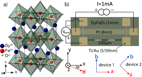
DFO is a perovskite with an orthorhombic ( - Pbnm) crystallographic structure. It consists of alternating Fe3+ and Dy3+ planes, in which the Fe ions are located inside O2- octahedrons (Fig. 1a)). The large Dy3+ magnetic moments () order at a low temperature, K. The high Néel temperature K indicates strong inter- and intra-plane AFM Heisenberg superexchange between the Fe3+ magnetic moments (). The AFM order of the Fe moments is of the G-type with Néel vector (anti)parallel to the crystallographic axis ( symmetry [14]). The broken inversion symmetry enables a DMI [15, 16] that in the -phase causes a WFM by the small () canting of the Fe spins [14].
A first-order Morin transition from the WFM -phase to the purely
AFM -phase occurs when lowering the temperature below 50 K. At
this transition, the direction of the magnetic easy axis abruptly changes from
the - to the -direction. A magnetic field higher than a critical
magnetic field, , along the axis re-orients the Néel
vector back to the axis and recovers the -phase. Below
, the Dy3+ moments form a noncollinear
Ising-like AFM order with Ising axes rotated by from the
axis [17] that corresponds to a
state in Bertaut’s notation [18]. The simultaneous presence of
ordered Fe and Dy magnetic moments breaks inversion symmetry and, under an
applied magnetic field, induces an electric polarization [19]
by exchange striction that couples the Fe and Dy magnetic sublattices
[6, 20]. Higher magnetic fields destroy the AFM order
of the Dy3+ moments and thereby the electric polarization [21].
Spins in this material can be controlled by light through the inverse Faraday effect [3], as well as by temperature and magnetic field. Re-orientation of the Fe moments has been studied by magnetometry [22], Faraday rotation [23], Mössbauer spectroscopy [24] and neutron scattering measurements [21]. The Morin transition at 50 K causes large changes in the specific heat [25] and entropy [26].
III probing methods
III.1 Spin Hall magnetoresistance
The SMR is caused by the spin-charge conversion in a thin heavy metal layer in contact with a magnet [27]. The spin Hall effect induces a spin current transverse to an applied charge current and thereby an electron spin accumulation at surfaces and interfaces. Upon reflection at the interface to a magnetic insulator, electrons experience an exchange interaction that depends on the angle between their spin polarization and that of the interface magnetic moments, while the latter can be controlled by an applied magnetic field. The reflected spin current is transformed back into an observable charge current by the inverse spin Hall effect. The interface exchange interaction is parameterized by the complex spin mixing conductance. The result is a modulation of the charge transport that depends on the orientation of the applied current and the interface magnetic order. In a Hall bar geometry, this affects the longitudinal resistance and causes a planar Hall effect, i.e. a Hall voltage even when the magnetic field lies in the transport plane.
SMR is a powerful tool to investigate the magnetic ordering at the interface of collinear [7, 27, 28, 29] and noncollinear ferrimagnets [30, 31] as well as spin spirals [32, 33]. Recently, a “negative” SMR has been discovered for AFMs [2, 8, 9, 10], i.e. an SMR with a phase shift of the angular dependence as compared to FMs, which shows that the AFM Néel vector tends to align itself normal to the applied magnetic field. The observable in AFMs is therefore the Néel vector rather than the net magnetization [2].
The longitudinal and transverse electrical resistivities and of Pt on an AFM read [2]
| (1) |
| (2) |
with and with as the Cartesian components of the (unit) Néel and the applied magnetic field vectors, respectively. is the out-of-plane (OOP) component of the unit vector in the direction of the WFM magnetization. is an angle-independent interface correction to the bulk resistivity . is the ordinary Hall resistivity of Pt in the presence of an OOP component of the magnetic field. is proportional to the real (imaginary) part of the interface spin-mixing conductance. is a resistance induced by the effective WFM field, believed to be small in most circumstances.
The interface Dy3+ moments can contribute to the SMR when ordered.
Below , the Dy3+ moments are AFM aligned with
Néel vector . Above and in sufficiently large applied magnetic fields, the
Dy3+ moments contribute to the SMR in Eqs. (1,2)
after replacing the Néel vector by the (nearly
perpendicular) magnetization .
Disregarding magnetic anisotropy and DMI for the moment, the spin mixing conductance term phase-shifts the SMR by relative to the pure
AFM contribution. The term changes sign with and its contribution cannot be distinguished from the ordinary Hall effect in Pt. We remove a linear magnetic field dependence from the OOP SMR measurements. Residual non-linear effects from may persist, but should be small in the phase. A finite has been
reported in conducting AFMs [34], but we do not observe a
significant contribution down to 60 K.
III.2 Spin Seebeck effect
A heat current in a FM excites a spin current that in insulators is carried mainly by magnons, the quanta of the spin wave excitations of the magnetic order. We can generate a temperature bias simply by the Joule heating of a charge current in a metal contact. A magnon flow can also be generated by a gradient of a magnon accumulation or chemical potential [35]. Therefore
| (3) |
with as the magnon spin conductivity and the spin Seebeck coefficient. Thermal magnons can typically diffuse over several [36, 37, 38], which implies that the SSE mainly probes bulk rather than interface magnetic properties. The magnons in simple AFMs typically come in degenerate pairs with opposite polarization that split under an applied magnetic field [39, 11]. The associated imbalance of the magnon populations cause a non-zero spin Seebeck effect [13]. Paramagnets display a field-induced SSE effect [38] for the same reason, so aligned Dy3+ moments can contribute to an SSE in DFO. A magnon accumulation at the interface to Pt injects a spin current that can be observed as an inverse spin Hall effect voltage , where is the spin Hall angle and is the spin polarization. The SMR and SSE can be measured simultaneously by a lock-in technique [40].
IV Methods
IV.1 Fabrication, characterization and measurements
We confirmed the crystallographic direction of our single crystal by X-ray diffraction before sawing it into slices along the ab plane and polishing them. Two devices were fabricated on different slices of the materials using a three step electron beam lithography process; markers were created to align the devices along two different crystallographic directions. After fabrication of an 8 nm thick Pt Hall bar, 50 nm Ti/Au contact pads were deposited.
The angular dependence of the magnetoresistance below 50 K is complex and hysteretic. Phase changes are associated by internal strains that can cause cracks in the bulk crystal. We therefore carried out magnetic field sweeps at low temperatures very slowly, with a waiting time of 60 seconds between each field step. The response was measured with a 1 mA (100A) AC current through the Pt Hall bar in device 1 (device 2) with a frequency of 7.777 Hz. The first and second harmonic transverse and longitudinal lock-in voltages as measured with a superconducting magnet in a cryostat with variable temperature insert are the SMR and SSE effects, respectively.
Below the transition temperature, the Morin transition is induced by a
magnetic field along the axis that rotates the Néel vector from
to . For device 1, this does not change the transverse
resistance since when the Néel
vector is in either the - or -direction. On the other hand, device 2 is
optimized for the observation of the Morin transition, because, as discussed
below, the transverse resistance should be maximally positive when
and maximally negative when .
IV.2 Modelling the SMR of PtDFO
The orientation of the Néel vector of the Fe sublattice at temperatures well above is governed by several competing interactions: (a) the magnetic anisotropy, which above the Morin transition favors , (b) the Zeeman energy that favors since the transverse magnetic susceptibility of an AFM is higher than the longitudinal one, and (c) the coupling of the WFM moment, , to the applied magnetic field. This competition can be described phenomenologically by the free energy density
| (4) |
with the first two terms describing the second-order magnetic anisotropy with magnetic easy, intermediate and hard axes along the , and crystallographic directions, respectively (), is the transverse magnetic susceptibility, and the is the weak ferromagnetic moment along the axis, induced by . , because the longitudinal susceptibility of the Fe spins is very small for . The magnetic field is chosen parallel to the plane, but can have an OOP component since the third term in Eq.(4) couples linearly to . For the SMR at 250 K, we may disregard higher-order magnetic anisotropies that become important near the Morin transition.
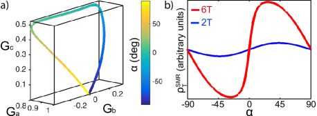
At weak magnetic fields, the magnetic anisotropy pins the Néel vector to the axis. When the Zeeman energy becomes comparable with the anisotropy energy, the rotation of the magnetic field vector in the plane gives rise to a concomitant rotation of . In the absence of magnetic anisotropy, the canting of the magnetic moments leads to for any magnetic field orientation due to the Zeeman energy rendering a sinusoidal SMR, but magnetic anisotropy can distort the angular dependence. This behavior is further complicated by the WFM: for strong magnetic fields along the axis, the Néel vector tilts away from the plane towards the axis, since the -component of induces a WFM moment parallel to the applied magnetic field [24, 41]. By contrast, does not give rise to a weak FM moment, so the Néel vector returns into the plane when we rotate the magnetic field away from the axis. The equilibrium Néel vector minimizes the free energy Eq. (4) under the constraint as a function of strength and orientation of the magnetic field with in-plane (IP) angle (see Fig. 1b)).
We adopt a weak magnetization parameters per ion induced either by along the axis [42] or by along the axis [43]. The transverse magnetic susceptibility can be estimated using the Heisenberg model with an Fe-Fe exchange constant meV for Y3Fe5O12 [44] , which leads to , which does not depend strongly on the rare-earth ion. governs the critical field when applied along the axis with T at K [24] that fully rotates from the to the direction. can then be estimated using . is the only free temperature-dependent parameter that we fit to the field-dependent SMR. All other constants are taken to be independent of temperature. A typical calculated dependence of and the corresponding contribution of the Fe spins to the SMR is shown in Fig. 2 (see below for a more detailed discussion).
Ordered rare-earth ions can also contribute to the SMR and SSE. The spectrum of the lowest-energy 6H15/2 multiplet of the Dy3+ ion (4f9 electronic configuration) consists of a Kramers doublet separated by cm from the first excited state [45]. At low temperatures, , the Dy moments behave as Ising spins tilted by an angle away from the axis in the plane (). At high temperatures, , they can be described as anisotropic Heisenberg spins with paramagnetic susceptibilities, for a magnetic field parallel (perpendicular) to the local spin-quantization axis () [46].
For , the SMR resulting from the contributions of the four Dy sublattices (four Dy sites in the crystallographic unit cell of DFO) is
| (5) |
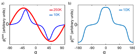
where the first term originates from the interaction of Dy spins with the applied magnetic field and the other two terms result from the exchange field induced by Fe spins on Dy sites (for a more detailed discussion of the effective magnetic field acting on Dy spins and the expressions for A and B in terms of the magnetic susceptibilities of the Dy ions see Appendix B). It can be inferred form Fig. 2 a) that is approximately proportional to . Therefore, all terms in Eq. 5 give the dependence of the transverse SMR at high temperatures (thick red line in Fig. 3 a)). Equation (5) should be added to the SMR caused by the iron sublattice with an unkown weight that is governed by the mixing conductance of the Dy sublattice. We may conclude however that an additional should not strongly change the shape of the SMR in Figure 2b).
At low temperatures, , , the Dy moments behave as Ising spins. A rotation of the magnetic field in the plane modulates the projection of the effective magnetic field on the local spin-quantization axes of the four Dy sublattices, which affects the angular dependence of the SMR. Since the paramagnetic model Eq. (5) cannot be used anymore, we compute the Dy contribution to the SMR numerically for the rare-earth Hamiltonian
| (6) |
with as the Dy total angular momentum, the Landé factor, the anisotropy parameter, which is known to reasonably describe the low-energy excited states of Dy ions and are the local easy axes rotated by , for the Dy sublattices 1 and 3, and , for the sublattices 2 and 4, away from the axis. The magnetic field acting on Dy spins is the sum of the applied field and the exchange field from Fe spins: , where the is for the sublattices and , respectively. We neglect the component of the exchange field, since the Dy magnetic moment along the is small and does not affect the SMR. Using the Hamiltonian Eq. (6), we calculate the average and components of the magnetic moments of the 4 Dy sublattices at a temperature and the resulting contributions to SMR. The angular dependence of the SMR due to Dy spins is plotted in Fig. 3 a).
The calculations recover the angular dependence of the SMR from Eq. (5) at high temperatures. At 10 K (blue line) the SMR curve becomes strongly deformed: The angular dependence of the SMR shows peaks and dips at the effective field directions orthogonal to the quantization axis of the -th rare-earth sublattice.
For long magnon relaxation time, the SSE generated a spin current that is assumed to be proportional to the bulk magnetization and can therefore provide additional information. We focus here on the low temperature regime because we did not observe an SSE at elevated temperature, which is an indication that the Dy magnetization plays an important role.
A net magnetization of rare-earth moments affects the SSE signals in gadolinium iron [47] and gadolinium gallium [38] garnets. We assume that the SSE is dominated by a spin current from the bulk that is proportional to the total magnetization of the four Dy sublattices that we calculated for the Hamiltonian Eq. (6) at 10 K as function of the angle of the applied magnetic field. The model predicts peaks at magnetic field directions aligned with the Ising-spin axes of the Dy moments, i.e. in between those canted by , which enhances the magnetization. The contribution from the Fe sublattice to the SSE is expected to depend as on the external magnetic field direction [48]. The ratio of the Fe and Dy contributions to SSE is unknown.
V Results
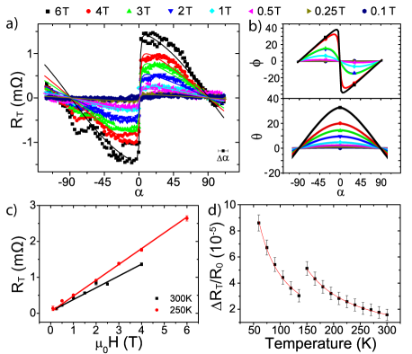
The SMR was measured by rotating an IP magnetic field of various strengths. Temperature drift and noise swamped the small signal in the longitudinal resistance as discussed in Appendix A. Figure 4 a) shows the measured resistance of device 1 at 250 K in the transverse (planar Hall) configuration using the left contacts in Fig. 1 b). The results for the right Hall contacts (not shown) are very similar.
The (negative) sign of the SMR agrees with our Fe sublattice model, suggesting that it is caused by the AFM ordered Fe spins with Néel vector normal to the applied magnetic field. However, cannot be strictly normal to the magnetic field, because the SMR is not proportional to , as observed for example in NiO [2]. The strongly non-sinusoidal angular dependence of the SMR is evidence for a non-trivial path traced by the Néel vector in an applied magnetic field as predicted by the model Eq. (4).
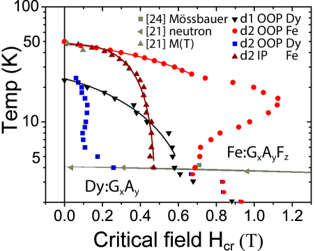
Figure 2 a) shows the dependence of the three components , and of the Néel vector on the IP orientation angle of the magnetic field, for T. The value of is indicated by the color code side bar. When , the magnetic field causes a tilt of away from the easy axis towards the hard axis since the Néel vector parallel to the axis induces a magnetization along the axis. The excursion of from the plane effectively reduces the role of the IP magnetic anisotropy, which leads to a large rotation of the Néel vector in the plane for small (at nearly constant ). As explained above, this rotation is driven by the Zeeman energy of the AFM ordered Fe spins (the third term in Eq.(4)), which favors and competes with the magnetic anisotropy that favors (the first term in Eq.(4)). This behavior is similar to the spin-flop transition for a magnetic field applied along the magnetic easy axis, except that does not become fully orthogonal to the magnetic field. As the magnetic field vector rotates away from the axis, and decrease, and at , is parallel to the axis.
The sensitivity of to small gives rise to an abrupt change of the transverse SMR that is proportional to close to (thick red line Fig. 2b). The calculated and observed SMR scans agree well for K and T. Surprisingly, the shape of the experimental curves is practically the same at all magnetic field strengths, i.e. the SMR jumps at even at weak fields, while the calculation approach the geometrical dependence (thin blue line in Fig. 2b) calculated for T). The fits of the observed SMR for all magnetic fields require a strongly field-dependent IP anisotropy parameter that is very small in the zero field limit: K (see Fig. 4a). At present we cannot explain this behavior. The Dy3+ moments should not play an important role in this regime unless a Pt induced anisotropy at the DFO/Pt interface modifies their magnetism (see below).
The exchange coupling between the rare-earth and transition-metal magnetic subsystems is reflected by the second term in Eq.(5) of the Dy3+ contribution to the SMR that is proportional to , i.e. the AFM order of the Fe spins. Since, is a smooth function at , it cannot be hold responsible for the large zero-field magnetoresistance. The angular SMR appears to be dominated by the Néel vector of the Fe moments, in contrast to SmFeO3, in which the Sm-ions determine not only the amplitude but also the sign of the SMR [49].
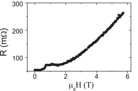
The linear increase of the SMR with magnetic field strength (see Fig. 4c)) can partly be explained by the growth of the maximum IP rotation angle, , of the Néel vector with magnetic field. However, deviations from the linear dependence are then expected close to the critical value, T, at which the re-orientation transition from to in is complete [24]. Nevertheless, the SMR signal shows no sign of saturation at T and K. The of Dy becomes of the order of kBT at a magnetic field strength of 37 T, indicating contributions from the paramagnetic rare earth spins remains linear in the applied field strengths.
Further evidence for rare earth contributions at higher temperatures is the Curie-like power-law temperature dependence of the SMR (see Fig. 4d)) , with at low temperatures and at high temperatures.111We have not been able to identify the mechanism for the step observed between 135 K and 150 K that has to our knowledge not been reported elsewhere either. For comparison, in the AFM NiO, is positive and the SMR signal grows quadratically with the AFM order parameter [2]. At temperatures well below the Néel transition K, the Fe based magnetic order is nearly temperature independent. The strong magnetic field and temperature dependence therefore suggest important contributions from polarized Dy3+ moments even at room temperature.
The puzzling strong magnetic field-dependence of from the data fit might indicate a different coupling between the rare earth and transition metal magnetic subsystems at the interface and in the bulk. It can be justified by the following symmetry argument. The generators of the Pbnm space group of the DFO crystal are three (glide) mirror planes: , and , i.e. a mirror reflection combined with a shift along a direction parallel to the mirror plane. is broken at the interface normal to the axis. In the absence of , the rare earth order parameters and transform to that describes the AFM order of Fe spins, which allows for a linear coupling between the rare earth and Fe spins at the interface. Since strongly depends on at , the same may hold for the rare earth moments at the interface. The SMR is very surface sensitive and could be strongly affected by this coupling.
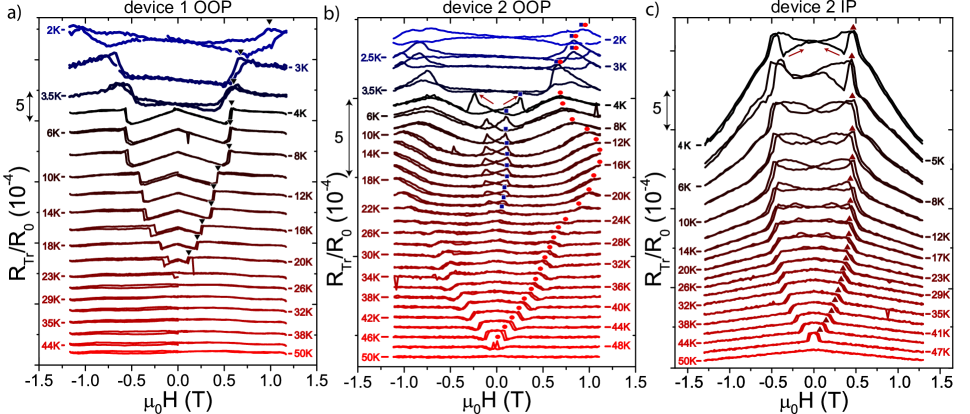
Next, we turn to the SMR at temperatures below the Morin transition at magnetic fields around the re-entrant field, . Figure 5(a) shows the transverse SMR of device 1 in an OOP magnetic field, while the data for longitudinal resistance are deferred to the Appendix A, Fig. 8a). We subtracted a linear field dependent contribution from the OOP data that is caused by the ordinary Hall effect in Pt.
The zero-field resistance of device 1 should not change under the Morin transition when the Néel vector direction switches from to nor should it be affected by weak magnetic fields (T near 50 K [21]) that return the system to . Indeed, we do not see any weak-field anomaly of the SMR near 50 K in Fig. 5a). However, below 23 K, a negative SMR proportional to the applied field appears. The linear field-dependence ends abruptly with a positive step-like discontinuity (see Fig. 5a)). No resistance offset has been observed between the zero-field and the high-field phases. After substraction of the strictly linear ordinary Hall effect contribution, the SMR feature is an even function of . The magnetic phase transition at 23 K appears to be unrelated to the Morin transition and has not been reported previously.
The Morin transition is clearly observed in the OOP and IP SMR of device 2, in which the crystallographic axes are azimuthally rotated by relative to the Hall bar as shown in Fig. 1b). Here, an SMR signal is expected for both magnetic phases and the rotation of the Néel vector from to should change its sign from positive for the AFM phase () to negative for the WFM phase (), for . The phase can also be suppressed by an IP field that rotates the Néel vector towards to lower the Zeeman energy. The drop in the Hall resistance observed in device 2 below 48 K for the OOP (Fig. 5 b)) and IP (Fig. 5 c)) field directions can therefore be ascribed to the Morin transition with a temperature-dependent . The SMR steps are negative, as expected.
At even lower temperatures the model appears to break down since we observe hysteretic behavior in the field-dependence of the SMR signal at low magnetic fields for both the OOP and IP directions. These features come up below 23 K, so appear to have the same origin as the anomalies in device 1. For the OOP direction, the low-field anomalies in device 2 are peaks while they are step-like in device 1. Wang et al.[21] did not observed a hysteresis in the Fe3+ magnetic sublattice and suggested that observed hysteretic behaviour [6, 51] is an evidence for long-range to short-range Dy3+ magnetic order. The SMR might witness an ordering of Dy3+ moments at the interface at a higher temperature than in the bulk that cannot be detected by other measurements.
Another unexpected feature is a linear negative magnetoresistance at for the IP configuration (see Fig. 5c)) that might be caused by a canting of towards by [24]. A misalignment of the crystallographic axes could also affect the SMR more significantly for high magnetic fields. However, neither of these mechanisms explain the IP magnetic field dependence and the peaks and low magnetic field features in the OOP measurements of both devices below 23 K (Fig. 5a) and 5b)). Since their signs and shapes vary, we can exclude a paramagnetic OOP canting of the Dy3+ orbital moments. The Dy3+ orbital moments are locked to the Ising axis in the plane and the magnetization is one order of magnitude larger in this plane than along the direction [6]. This might explain the IP SMR features in terms of an IP field and temperature dependent order of the Dy3+ moments.
The 90∘ spin reorientation at the Morin transition maximizes the Fe3+ contribution to the SMR. The increase of the IP signal amplitude by one order of magnitude upon lowering the temperature, see Fig. 5(c) is therefore unexpected. The signals become as large as 1%, one order of magnitude larger than the SMR signals of Pt on Y3Fe5O12 [7, 27, 28, 29] and a factor four larger than that of -Fe2O3 [52]. Ordered Dy3+ magnetic moments appear to be responsible for the anomalous signals below 23 K. They interact with the Fe sublattice by the exchange interaction, as observed before in the multiferroic phase at temperatures exceeding under a 0.5 T magnetic field [21]. A contribution of Dy3+ moments to the magnetization has also been observed in terms of an upturn of the magnetization and hyperfine field below 23 K [53].
The SMR steps in device 1 around K at which the Dy moments order spontaneoulsy, are similar to those at higher temperature, which supports the hypothesis that the latter are also related to Dy3+ order. Device 2 shows an increased Hcr matching those in device 1 at these temperatures. Both devices show no non-linear antisymmetric field dependence, indicating that the Dy3+ ordering above 4 K is field-induced. Li et al. [51] observed jumps in the thermal conductivity around 4 T and attributed these to a spin reorientation of the Fe sublattice. However, no further transitions are observed up to 6 T as is shown in Appendix A, so we cannot confirm such an Fe3+ transition.
The magnetic field and temperature of the occurrences of SMR steps at spin transitions and of SMR anomalies are collected in Fig. 6, including the peaks in the OOP measurements of device 2, using the same markers as in Fig. 5. The data on the Morin transition agrees with previous observations [21, 24]. The Morin point for both IP an OOP configurations is around 50 K, whereas the transitions ascribed to an ordering of the Dy3+ moments occur around 23 K. Upon lowering the temperature, the transitions associated to the Dy3+ and Fe3+ moments approach each other and merge below , which is another indication of a strong inter-sublattice exchange interaction.
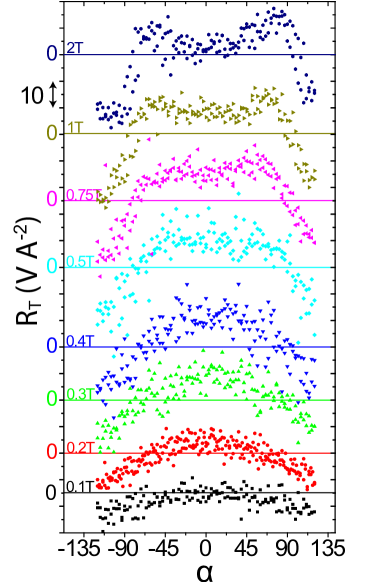
Figure 7 summarizes the observed IP SSE data of device 1 at 10 K. The angular dependence of the resistance at small fields shows the dependence, indicating that the magnon spin current injected into Pt is constant with angle. The amplitude initially increases linearly with field, but decreases again for T. The SSE signal of a uniaxial AFM has dependence for an IP rotating magnetic field [48]. The SSE is small at angles for which our model for the Dy3+ contribution in Fig. 3b) predicts a peak. However, we do not observe the expected Dy3+-induced SSE contribution due to the Dy3+ magnetization shown in Fig. 3. On the contrary, an increase in Dy3+ magnetization appears to suppress the SSE signal. These results suggest that the angular dependence of the SSE is governed not so much by the ordering of the Dy spins, but by their effect on the frequencies of the antiferromagnons in the Fe magnetic subsystem. The ordering of Dy spins leads to a hardening of the AFM resonance modes [54]. The applied magnetic field suppresses the Dy spin ordering and results in a substantial decrease of the spin gap [54] , which affects the thermal magnon flux and, hence, the SSE. At room temperature, the SSE signal does not rise above the noise level of 0.18 V A-2.
VI Conclusion
We studied the rare earth ferrite DFO by measuring the transverse electric resistance in Pt film contacts as function of temperature and applied magnetic field strength and direction. Results are interpreted in terms of SMR and SSE for magnetic configurations that minimize a magnetic free energy model with magnetic anisotropies, Zeeman energy and DMI. The Néel vector appears to slowly rotate OOP and displays jumps under IP rotating magnetic fields. Magnetic field-strength dependences indicate that Fe3+ spins are responsible for the symmetry of the SMR, but that the Dy3+ orbital moments affect the amplitude. The first-order Morin transition is clearly observed at temperatures below 50 K. Additional sharp features emerge below 23 K at critical fields below that of the Morin transition. These observed features cannot be understood by the Fe3+ Néel vector driven SMR. Rather, they suggest a magnetic field-induced ordering of Dy3+ established by the competition between applied magnetic and exchange fields with Fe3+. This hypothesis is supported by the similar SMR features at the spontaneous Dy3+ moment ordering temperature . A Dy3+ order above also appears to suppress the SSE contributions from the Fe sublattice.
Concluding, we report simultaneous manipulation and monitoring of the ordering
of both transition metal and rare earth magnetic sublattices and their
interactions as a function of temperature and magnetic field in the complex
magnetic material DFO.
VII Acknowledgements
We thank A. Wu for growing the single crystal DyFeO3, J. G. Holstein, H. Adema, T. J. Schouten, H. H. de Vries and H. M. de Roosz for their technical assistance as well as R. Mikhaylovskiy and A. K. Zvezdin for discussions. This work is part of the research program Magnon Spintronics (MSP) No. 159 financed by the Nederlandse Organisatie voor Wetenschappelijk Onderzoek (NWO) and JSPS KAKENHI Grant Nos. 19H006450, and the DFG Priority Programme 1538 Spin-Caloric Transport (KU 3271/1-1). Further, the Spinoza Prize awarded in 2016 to B. J. van Wees by NWO is gratefully acknowledged
References
- Loth et al. [2012] S. Loth, S. Baumann, C. P. Lutz, D. M. Eigler, and A. J. Heinrich, Science 335, 196 (2012).
- Hoogeboom et al. [2017] G. R. Hoogeboom, A. Aqeel, T. Kuschel, T. T. M. Palstra, and B. J. van Wees, Applied Physics Letters 111, 052409 (2017).
- Afanasiev et al. [2016] D. Afanasiev, B. A. Ivanov, A. Kirilyuk, T. Rasing, R. V. Pisarev, and A. V. Kimel, Physical Review Letters 116, 097401 (2016).
- Wadley et al. [2016] P. Wadley, B. Howells, J. Železný, C. Andrews, V. Hills, R. P. Campion, V. Novák, K. Olejník, F. Maccherozzi, S. S. Dhesi, S. Y. Martin, T. Wagner, J. Wunderlich, F. Freimuth, Y. Mokrousov, J. Kuneš, J. S. Chauhan, M. J. Grzybowski, A. W. Rushforth, K. Edmond, B. L. Gallagher, and T. Jungwirth, Science 351, 587 (2016).
- Moriyama et al. [2018] T. Moriyama, K. Oda, T. Ohkochi, M. Kimata, and T. Ono, Scientific reports 8, 14167 (2018).
- Tokunaga et al. [2008] Y. Tokunaga, S. Iguchi, T. Arima, and Y. Tokura, Physical Review Letters 101, 097205 (2008).
- Nakayama et al. [2013] H. Nakayama, M. Althammer, Y. T. Chen, K. Uchida, Y. Kajiwara, D. Kikuchi, T. Ohtani, S. Geprägs, M. Opel, S. Takahashi, R. Gross, G. E. W. Bauer, S. T. B. Goennenwein, and E. Saitoh, Physical Review Letters 110, 206601 (2013).
- Fischer et al. [2018] J. Fischer, O. Gomonay, R. Schlitz, K. Ganzhorn, N. Vlietstra, M. Althammer, H. Huebl, M. Opel, R. Gross, S. T. B. Goennenwein, and S. Geprägs, Physical Review B 97, 014417 (2018).
- Ji et al. [2018] Y. Ji, J. Miao, Y. M. Zhu, K. K. Meng, X. G. Xu, J. K. Chen, Y. Wu, and Y. Jiang, Appl. Phys. Lett. 112, 232404 (2018).
- Lebrun et al. [2019] R. Lebrun, A. Ross, O. Gomonay, S. Bender, L. Baldrati, F. Kronast, A. Qaiumzadeh, J. Sinova, A. Brataas, R. Duine, and M. Kläui, Communications Physics 2, 50 (2019).
- Wu et al. [2016] S. M. Wu, W. Zhang, A. Kc, P. Borisov, J. E. Pearson, J. S. Jiang, D. Letterman, A. Hoffmann, and A. Bhattacharya, Physical Review Letters 116, 097204 (2016).
- Rezende and Mendes [2017] S. M. Rezende and J. B. S. Mendes, Applied Physics Letters 111, 172405 (2017).
- Hoogeboom and van Wees [2020] G. R. Hoogeboom and B. J. van Wees, Physical Review B 102, 214415 (2020).
- Turov [1963] E. A. Turov, Physical Properties of Magnetically Ordered Crystals (Izd. Akad. Nauk SSSR, 1963).
- Dzyaloshinsky [1958] I. Dzyaloshinsky, J. Phys. Chem. Solids 5, 253 (1958).
- Moriya [1960] T. Moriya, Physical Review 120, 91 (1960).
- Holmes et al. [1972] L. M. Holmes, L. G. Van Uitert, R. R. Hecker, and G. W. Hull, Physical Review B 5, 138 (1972).
- Bertaut [1963] E. F. Bertaut, “Spin Configurations of Ionic Structures: Theory and Practice.” (1963).
- Yamaguchi and Tsushima [1973] T. Yamaguchi and K. Tsushima, Physical Review B 8, 5187 (1973).
- Stroppa et al. [2010] A. Stroppa, M. Marsman, G. Kresse, and S. Picozzi, New Journal of Physics 12, 093026 (2010).
- Wang et al. [2016] J. Wang, J. Liu, J. Sheng, W. Luo, F. Ye, Z. Zhao, X. Sun, S. A. Danilkin, G. Deng, and W. Bao, Physical Review B 93, 140403(R) (2016).
- Belov et al. [1974] P. Belov, A. K. Zvezdin, M. Kadomtseva, and I. B. Krynetskii, Journal of Experimental and Theoretical Physics 40, 980 (1974).
- Maziewski and Szymczak [1977] A. Maziewski and R. Szymczak, Journal of Physics D: Applied Physics 10, 37 (1977).
- Prelorendjo et al. [1980] L. A. Prelorendjo, C. E. Johnson, M. F. Thomas, and B. M. Wanklyn, Journal of Physics C: Solid State Physics 13, 2567 (1980).
- Zhang et al. [2015] F. Zhang, S. Li, J. Song, J. Shi, and X. Sun, IEEE Transactions on Magnetics 51, 1000904 (2015).
- Ke et al. [2015] Y. J. Ke, X. Q. Zhang, H. Ge, Y. Ma, and Z. H. Cheng, Chinese Physics B 24, 037501 (2015).
- Chen et al. [2013] Y. T. Chen, S. Takahashi, H. Nakayama, M. Althammer, S. Goennenwein, E. Saitoh, and G. Bauer, Physical Review B 87, 144411 (2013).
- Vlietstra et al. [2013] N. Vlietstra, J. Shan, V. Castel, J. Ben Youssef, G. E. W. Bauer, and B. J. van Wees, Applied Physics Letters 103, 032401 (2013).
- Althammer et al. [2013] M. Althammer, S. Meyer, H. Nakayama, M. Schreier, S. Altmannshofer, M. Weiler, H. Huebl, S. Geprägs, M. Opel, R. Gross, D. Meier, C. Klewe, T. Kuschel, J. M. Schmalhorst, G. Reiss, L. Shen, A. Gupta, Y. T. Chen, G. E. W. Bauer, E. Saitoh, and S. T. B. Goennenwein, Physical Review B 87, 224401 (2013).
- Ganzhorn et al. [2016] K. Ganzhorn, J. Barker, R. Schlitz, B. A. Piot, K. Ollefs, F. Guillou, F. Wilhelm, A. Rogalev, M. Opel, M. Althammer, S. Geprägs, H. Huebl, R. Gross, G. E. W. Bauer, and S. T. B. Goennenwein, Physical Review B 94, 094401 (2016).
- Dong et al. [2018] B. W. Dong, J. Cramer, K. Ganzhorn, H. Y. Yuan, E. J. Guo, S. Goennenwein, and M. Kläui, Journal of Physics: Condensed Matter 30, 035802 (2018).
- Aqeel et al. [2015] A. Aqeel, N. Vlietstra, J. A. Heuver, G. E. Bauer, B. Noheda, B. J. Van Wees, and T. T. Palstra, Physical Review B 92, 224410 (2015).
- Aqeel et al. [2016] A. Aqeel, N. Vlietstra, A. Roy, M. Mostovoy, B. J. Van Wees, and T. T. Palstra, Physical Review B 94, 1334418 (2016).
- Zhao et al. [2019] K. Zhao, T. Hajiri, H. Chen, R. Miki, H. Asano, and P. Gegenwart, Physical Review B 100, 45109 (2019).
- Cornelissen and Van Wees [2016] L. J. Cornelissen and B. J. Van Wees, Physical Review B 93, 020403 (2016).
- Cornelissen et al. [2015] L. J. Cornelissen, J. Liu, R. A. Duine, J. b. Youssef, and B. J. Van Wees, Nature Physics 11, 1022 (2015).
- Lebrun et al. [2018] R. Lebrun, A. Ross, S. A. Bender, A. Qaiumzadeh, L. Baldrati, J. Cramer, A. Brataas, R. A. Duine, and M. Kläui, Nature 561, 222 (2018).
- Oyanagi et al. [2019] K. Oyanagi, S. Takahashi, L. J. Cornelissen, J. Shan, S. Daimon, T. Kikkawa, G. Bauer, B. J. van Wees, and E. Saitoh, Nature Communications 10, 4740 (2019).
- Cheng et al. [2014] R. Cheng, J. Xiao, Q. Niu, and A. Brataas, Physical Review Letters 113, 057601 (2014).
- Vlietstra et al. [2014] N. Vlietstra, J. Shan, B. J. van Wees, M. Isasa, F. Casanova, and J. B. Youssef, Physical Review B 90, 174436 (2014).
- Eremenko et al. [1987] V. V. Eremenko, S. L. Gnatchenko, N. F. Kharchenko, P. P. Lebedev, K. Piotrowski, H. Szymczak, and R. Szymczak, Europhysics Letters 11, 1327 (1987).
- Cao et al. [2016] S. Cao, L. Chen, W. Zhao, K. Xu, G. Wang, Y. Yang, B. Kang, H. Zhao, P. Chen, A. Stroppa, R. Zheng, J. Zhang, W. Ren, J. Íñiguez, and L. Bellaiche, Scientific Reports 6, 37529 (2016).
- Zvezdin et al. [1985] A. K. Zvezdin, V. M. Matveev, A. A. Mukhin, and A. I. Popov, Moscow, Izd. Nauk , 296 (1985).
- Hahn et al. [2014] C. Hahn, G. de Loubens, V. V. Naletov, J. B. Youssef, O. Klein, and M. Viret, European Physics Letters 108, 571 (2014).
- Zvezdin and Matveev [1979] A. K. Zvezdin and V. M. Matveev, Zh. Eksp. Teor. Fiz., Tech. Rep. 3 (1979).
- Valiev et al. [2003] U. V. Valiev, J. B. Gruber, S. A. Rakhimov, and O. A. Nabelkin, physica status solidi (b) 237, 564 (2003).
- Geprägs et al. [2016] S. Geprägs, A. Kehlberger, F. Coletta, Z. Qiu, E. J. Guo, T. Schulz, C. Mix, S. Meyer, A. Kamra, M. Althammer, H. Huebl, G. Jakob, Y. Ohnuma, H. Adachi, J. Barker, S. Maekawa, G. E. W. Bauer, E. Saitoh, R. Gross, S. T. B. Goennenwein, and M. Kläui, Nature Communications 7, 10452 (2016).
- Yuan et al. [2018] W. Yuan, Q. Zhu, T. Su, Y. Yao, W. Xing, Y. Chen, Y. Ma, X. Lin, J. Shi, R. Shindou, X. C. Xie, and W. Han, Science Advances 4, 1098 (2018).
- Hajiri et al. [2019] T. Hajiri, L. Baldrati, R. Lebrun, M. Filianina, A. Ross, N. Tanahashi, M. Kuroda, W. L. Gan, T. O. Menteş, F. Genuzio, A. Locatelli, H. Asano, and M. Kläui, Journal of Physics: Condensed Matter 31, 445804 (2019).
- Note [1] We have not been able to identify the mechanism for the step observed between 135K and 150K that has to our knowledge not been reported elsewhere either.
- Zhao et al. [2014] Z. Y. Zhao, X. Zhao, H. D. Zhou, F. B. Zhang, Q. J. Li, C. Fan, X. F. Sun, and X. G. Li, Physical Review B 89, 224405 (2014).
- Fischer et al. [2020] J. Fischer, M. Althammer, N. Vlietstra, H. Huebl, S. Goennenwein, R. Gross, S. Geprägs, and M. Opel, Physical Review Applied 13, 014019 (2020).
- Reddy et al. [2015] S. S. K. Reddy, N. Raju, C. G. Reddy, P. Y. Reddy, K. R. Reddy, and V. R. Reddy, Journal of Magnetism and Magnetic Materials 396, 214 (2015).
- Stanislavchuk et al. [2016] T. N. Stanislavchuk, Y. Wang, Y. Janssen, G. L. Carr, S. W. Cheong, and A. A. Sirenko, Physical Review B 93, 094403 (2016).
- Gnatchenko et al. [1994] S. L. Gnatchenko, K. Piotrowski, A. Szewczyk, R. Szymczak, and H. Szymczak, Journal of Magnetism and Magnetic Materials 129, 307 (1994).
- Han et al. [2014] J. H. Han, C. Song, F. Li, Y. Y. Wang, G. Y. Wang, Q. H. Yang, and F. Pan, Physical Review B 90, 144431 (2014).
- Oyanagi et al. [2020] K. Oyanagi, J. M. Gomez-Perez, X. Zhang, T. Kikkawa, Y. Chen, E. Sagasta, L. E. Hueso, V. N. Golovach, F. S. Bergeret, F. Casanova, and E. Saitoh, arXiv:2008.02446 (2020).
Appendix A Longitudinal and 2 K SMR
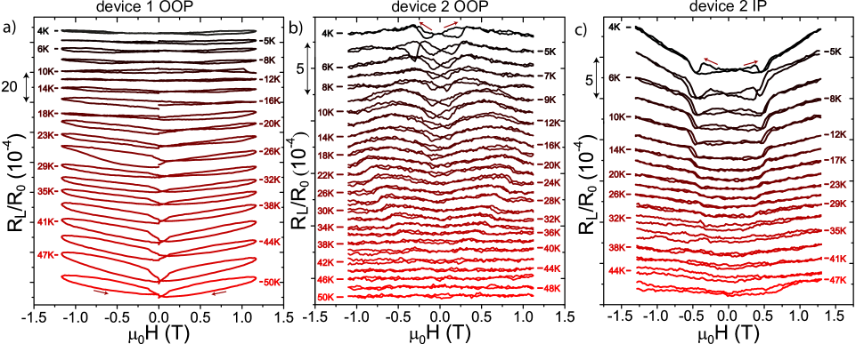
The modulation of the longitudinal Pt resistance as a function of magnetic field are shown in Fig. 8 for comparison with the transverse SMR. The longitudinal signals are affected by a background contact resistance that is sensitive to temperature changes. The SMR signals are therefore more distorted by a small temperature drift than the transverse measurements. Moreover, the background resistance suffer from increased noise.
The OOP resistance changes of device 1 are one order of magnitude larger than those of device 2 and dominated by hysteretic effects. The signal amplitudes of OOP and IP configurations for device 2 are similar. The measurement time of one data point below 0.2 T is smaller than at larger fields, influencing the shape of the graphs. Device 2 shows hysteretic features at low magnetic fields and below 23 K, for both IP and OOP magnetic fields that are similar to the transverse SMR features discussed in the main text.
Appendix B Exchange interaction
The Pbnm crystal symmetry allows an exchange coupling between the Dy3+ moments and G-type AFM ordered Fe spins. The coupling of the 4 (individual) Dy spins in the unit cell with the Fe spins is described as
| (7) |
where the indices label the rare-earth ions in the unit cell. The exchange field from Fe ions is estimated to be T at low temperatures [45].
For , the magnetization of the Dy sublattice and for field components parallel and perpendicular to the local anisotropy axis and . We assume that the transverse SMR caused by the paramagnetic Dy3+ moments polarized by the applied field is proportional to [9, 56, 32, 57]. Adding the contributions of the four Dy sites in the crystallographic unit cell of DFO and the exchange field from the Fe spins acting on the Dy spins as described in the main text, we obtain Eq. 5 with and . The coupling constants g3 and g4 do not appear in the expression for SMR since the latter does not depend on the c-component of Dy spins. Moreover, the c-component is very small at low temperatures, since the easy axes of Dy ions lie in the ab plane. Both g1 and g2 lead to (nearly) the same angular dependence of SMR.