Vinícius da Silva, Tiago Novello, Hélio Lopes, Luiz Velho \setcitetitleProceduray – A light-weight engine for procedural primitive ray tracing. \submitted
![[Uncaptioned image]](/html/2012.10357/assets/figs/procedural_scene.png)
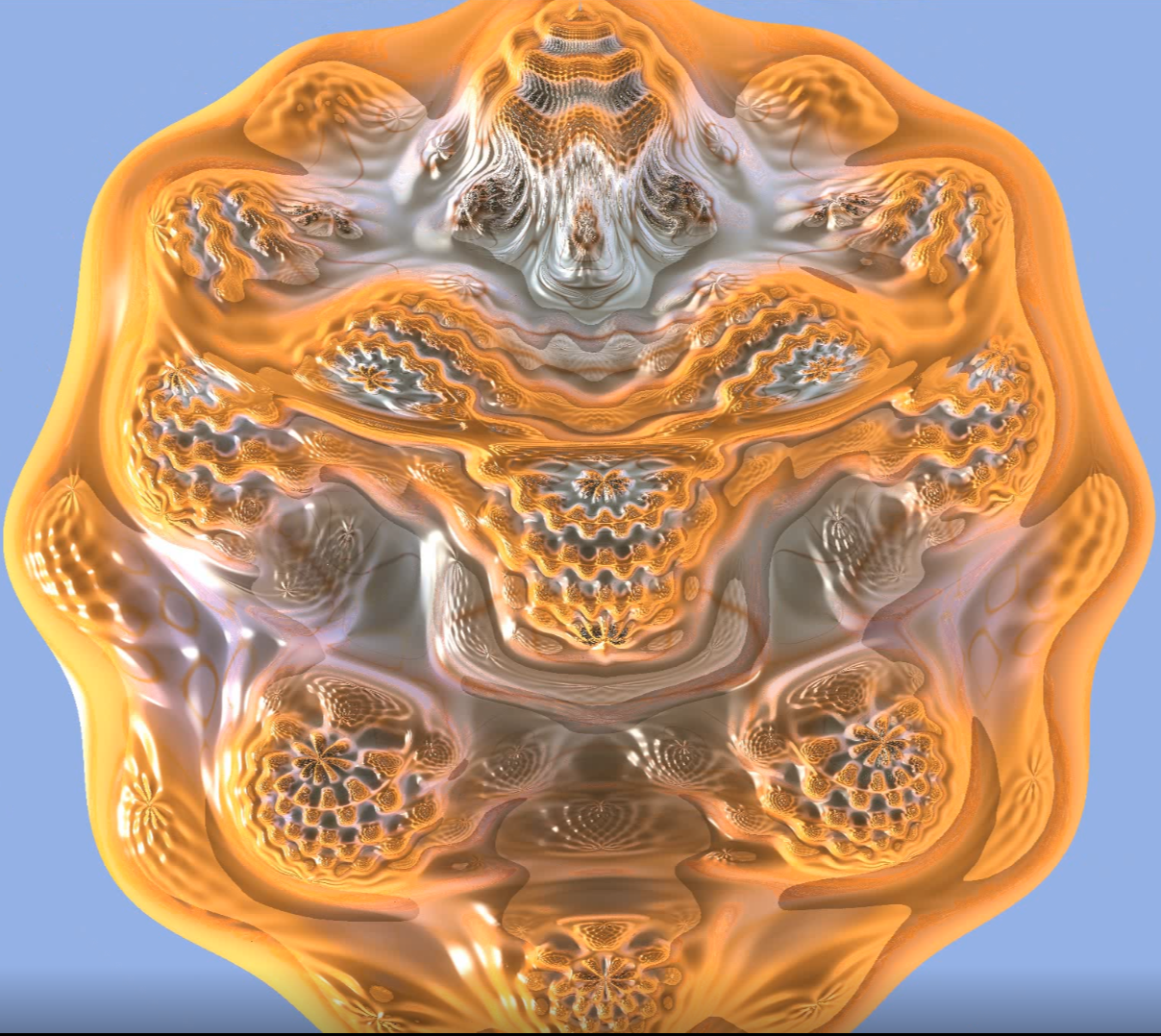
A scene with procedural objects (two pac-men, a julia set and a mandelbulb).
Proceduray – A light-weight engine for procedural primitive ray tracing.
Abstract
We introduce Proceduray, an engine for real-time ray tracing of procedural geometry. Its motivation is the current lack of mid-level abstraction tools for scenes with primitives involving intersection shaders. Those scenes impose strict engine design choices since they need flexibility in the shader table setup. Proceduray aims at providing a fair tradeoff between that flexibility and productivity. It also aims to be didactic. Shader table behavior can be confusing because parameters for indexing come from different parts of a system, involving both host and device code. This is different in essence from ray tracing triangle meshes (which must use a built-in intersection shader for all objects) or rendering with the traditional graphics or compute pipelines. Additionals goals of the project include fomenting deeper discussions about DirectX RayTracing (DXR) host code and providing a good starting point for developers trying to deal with procedural geometry using DXR.
1 Introduction
Given the potential of the RTX architecture for real-time graphics applications, important game engines [\citenameHaas 2014, \citenameEpic Games], scientific graphics frameworks [\citenameBenty et al. 2020] and 3D creation software [\citenameCommunity 2018] hastily incorporated it. Currently, several important 3D development tools support ray tracing triangle geometry using RTX.
1.1 RTX in 3D development tools
Tools supporting high-level abstraction workflows using RTX are limited to Falcor [\citenameBenty et al. 2020], Unreal [\citenameEpic Games], and Unity [\citenameHaas 2014]. There are other choices for development using RTX, but they are either lower-level abstraction libraries [\citenameMcGuire et al. 2019, \citenameParker et al. 2010, \citenameSellers and Kessenich 2016, \citenameHaines and Akenine-Möller 2019] or non-interactive ray tracers [\citenameMours 2019].
Those tools differ in how they approach RTX, however. For example, Falcor [\citenameBenty et al. 2020] has a more straightforward integration with the platform, providing very informative samples, including code to use ray-generation, closest-hit, any-hit, and miss shaders, and a path tracer. It did not support intersection shaders or procedural geometry until version 4.3, which debuted in December 2020. This version documents its API for working with procedural geometry, but it does not have examples on the matter yet.
Unity [\citenameHaas 2014] and Unreal [\citenameEpic Games] have specific development branches [\citenameUnity 2020, \citenameNVidia 2020] with RTX enabled. As Falcor, Unity supports customized RTX shaders [\citenameNing a, \citenameNing b], but does not work with intersection shaders. Unreal takes a different approach. Even though it has the most sophisticated RTX-based real-time ray tracer of all the alternatives, it can only be used as an effect, which can be turned on or off and be given parameters. We conjecture that Unreal has everything needed to support customized RTX shaders internally, but it currently lacks documentation and examples on the matter [\citenameUnknown 2020b, \citenameUnknown 2020c, \citenameUnknown 2020a].
1.2 Real-time ray-traced procedural geometry
The fact that more than two years after the RTX launch the majority of the state-of-the-art 3D development tools do not support it in its full potential evidence that deeper discussions on the matter are necessary.
Although triangle geometry is most common for rendering purposes, RTX also supports procedural geometry. This feature includes control of the intersection behavior, which directly impacts how expressive a ray type can be. An immediate consequence is another level of flexibility available to applications. Additionally, procedural geometry imposes little resource maintenance in comparison with triangles since device code is directly responsible for defining geometry, instead of just receiving it to process. A discussion that emerges from those points is how to deal with the procedural geometry inherent flexibility in a productive workflow supporting high-level abstractions.
1.3 Contributions and proposal
We propose Proceduray, a novel lightweight engine with native support for procedural primitive ray tracing, designed to be a fair compromise between flexibility and productivity. Other objectives of the project include expanding the discussion about DXR [\citenameMicrosoft 2020] host code and providing a good starting reference for procedural geometry in DXR. Currently, references about DXR device shader code are abundant [\citenameHaines and Akenine-Möller 2019, \citenameSilva and Velho 2019], but there are very scarce references about host code management, usually reduced to code samples in low-level abstraction libraries.
Proceduray was used to create all code for the chapter Real-time Rendering of Complex Fractals [\citenameda Silva et al. 2021], from Ray Tracing Gems 2 [\citenameMarrs et al. 2021]. This paper documents all host code for that chapter.
It is structured as follows. Section 2 presents background DXR concepts, necessary to understand the problems and the discussion. Section 3 describes in detail the problems that Proceduray deals with and the design choices to solve them. Section 4 discusses the host API. Finally, Section 5 concludes and discusses future works.
2 Background
DXR introduced a new rendering pipeline and several new graphics concepts with it. Since our objective is to write an engine using this technology, it is natural to first understand those ideas and how they relate with well-established ones, previously introduced by the rasterization and compute pipelines. We opt to be explicit and self-contained for the sake of novice developers. That said, most of this Section is an overview of very basic graphics development concepts and can be skipped by more experienced practitioners.
2.1 Summary
At a high abstraction level, the host application must perform a few tasks before being able to dispatch ray tracing using DXR:
-
•
Define an efficient way to detect ray-geometry intersections;
-
•
Customize behavior based on geometry type. In other words, a specific geometry should run a specific set of shaders;
-
•
Specify the resources needed for the shaders.
Our approach is to organize the background dependency concepts and develop from there until we know in detail how to perform each task, focusing on practical host resource management.
2.2 Graphics Concepts
Our objective in this section is to understand the building blocks needed to make resources available to DXR shaders, their dependencies, and their relationships.
2.2.1 Overview
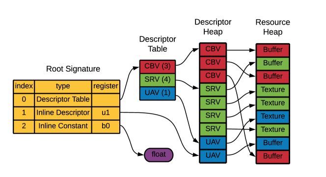
Every HLSL shader has an associated Root Signature, which is one of the most important concepts for shader resource management. The term Signature is not chosen randomly here: a shader Root Signature is analogous to a programming language function signature. As a function signature describes the arguments needed for a function, a Root Signature describes the resources needed for a shader. Figure 1 contains an overview of a Root Signature. We will explain its components in detail in the next sections.
For didactic purposes, the concepts are organized into two groups: graphics pipeline and ray tracing pipeline. In practice, however, they are mixed in applications.
2.2.2 Graphics pipeline
Resource:
It is every non-thread-local memory that is referenced by a shader, such as textures, constant buffers, images, and so on. Differently from thread-local variables, which are stored directly in device registers, Resource registers contain indirections for the actual data in a Resource Heap. Figure 1 depicts such an example, where register is an indirection to a Buffer. To make a resource available at shader execution time, one needs to use the concepts of Root Signatures, Descriptors, and Views.
Descriptor:
Resources are not bind directly to the shader pipeline; instead, they are referenced through a Descriptor. A Descriptor is a small object that contains information about one resource. It resides in a Descriptor Heap (see Figure 1).
Descriptor Heap:
a container for Descriptors.
Descriptor Table:
a set of references to Descriptors in Descriptor Heaps. It is composed of Descriptor Ranges. In Figure 1, entry 0 in the Root Signature is a Descriptor Table.
Descriptor Range:
a range of consecutive Descriptors in a Descriptor Heap. In Figure 1, the Descriptor Table entry is composed of 3 Descriptor Ranges, one for each View type. In the example all ranges are defined in the same Descriptor Heap for simplicity, but this is not an imposed restriction.
Views:
Resources are raw memory and Views describe how they can be interpreted. The most common types are:
-
1.
Constant Buffer Views (CBVs): structured buffers. In practice, they are structs transferred from host to device code.
-
2.
Shader Resource Views (SRVs): typically wrap textures in a format that shaders can access them.
-
3.
Unordered Access Views (UAVs): enable the reading and writing to the texture (or other resources) in any order. The other types just support reading or writing, not both.
-
4.
Samplers: encapsulate sampling information for a texture, such as a filter, uv-coordinate, and level-of-detail parameters.
Root Signatures:
Before DXR, only Global Root Signatures existed: when one was bound, it was visible to all shaders dispatched. Since DXR supports per-geometry customized shaders, Root Signatures can also be Local now. Global Root Signatures continue to be visible to all shaders, but Local Root Signatures can be set up to be used only when a specific geometry is ray-traced.
Figure 1 shows an example of a Root Signature, which can be composed by:
-
1.
Inline Constants, which are structs inlined directly at the Root Signature;
-
2.
Inline Descriptors, which are Descriptors inlined directly at the Root Signature;
-
3.
Descriptor Tables, which are references to Descriptors in Descriptor Heaps.
2.2.3 Ray tracing pipeline
Ray:
the entity that will be used to ray trace. It is composed of a Payload, which accompanies it throughout all the pipeline. This Payload is customizable (in practice, can be any plain-old-data (POD) struct) and can be updated by the ray tracing shaders.
Acceleration Structure:
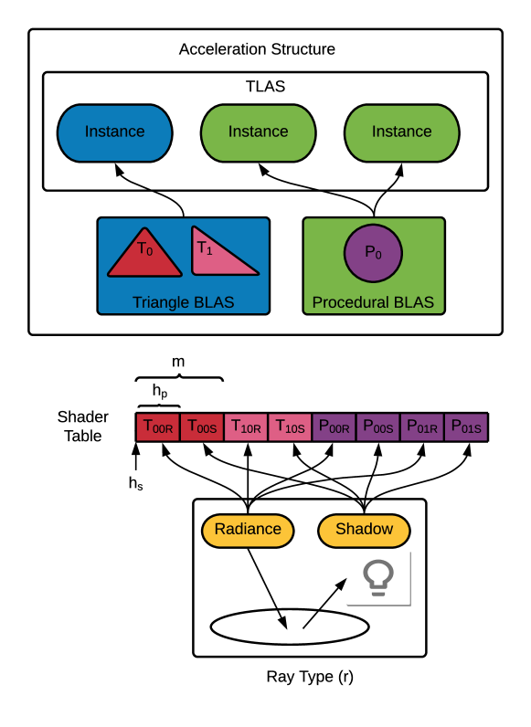
a hierarchical spatial data structure used to accelerate ray-geometry intersections. It is composed of Bottom-Level Acceleration Structures (BLAS) and Top-Level Acceleration Structures (TLAS). BLAS are the acceleration structures where the geometry lies in and TLAS are used for instancing (reusing) BLAS. The Acceleration Structure creation is performed by the DXR runtime but can be customized by parameters. BLAS creation for triangle and procedural geometry are different. A data structure optimized for triangle culling is constructed for the triangle case, while a simpler structure enclosing procedural geometry axis-aligned bounding boxes (AABBs) is constructed for the procedural case. Customized Intersection Shaders are responsible for the remaining intersection tests inside the AABBs. Figure 2 shows an overview of Acceleration Structures and Shader Tables, which will be detailed later on.
Ray Tracing Shaders:
They are called at different moments of the Acceleration Structure traversal by the DXR runtime.
-
1.
Ray Generation Shader: the starting point, where all initial rays are launched. Usually, each ray starts at the camera position and goes through a pixel.
-
2.
Miss Shader: issued when a ray misses all geometry. Receives the ray Payload as input.
-
3.
Any-hit Shader: called for all primitive intersections found. Its inputs are the ray Payload and a structure coming from the Intersection Shader.
-
4.
Closest-hit Shader: called for the primitive intersection closest to the ray origin. It has the same input types as the Any-hit Shader.
-
5.
Intersection Shader: called for computing intersections inside a BLAS AABB node. Custom intersection shaders are specific to procedural geometry (a built-in optimized Intersection Shader is used for triangle geometry). The result of the intersection shader indicates if an intersection is found, and the data that must be fed to the any-hit and closest-hit shaders potentially called by the runtime in consequence.
Hit Group:
a set of shaders that deal with a specific geometry. Specifically, one or more shaders consisting of: 0 or 1 Intersection Shader, 0 or 1 Any-hit Shader, 0 or 1 Closest-hit Shader. Hit groups are used in conjunction with Shader Tables and the Shader Table Indexing Rule to enable customized behavior for geometries. Ray Generation and Miss Shaders cannot be part of a Hit Group because they aren’t involved directly with geometry.
Shader Tables:
When traversing the Acceleration Structure, the runtime needs to know which Hit Group and shader parameters must be used when a BLAS node is reached. This information is fed to the pipeline through Shader Tables.
A Shader Table is composed of Ray-generation Shader Tables, Miss Shader Tables and Hit-group Shader Tables. We are interested on the hit-group shader tables, which enable customized behavior for geometries. They are very flexible and their entries must be set according to the Indexing Rule. This is the most important (and confusing) concept regarding Acceleration Structure behavior and flexibility. It is defined by the following equation:
| (1) |
where:
-
•
is the address of the Shader Table record;
-
•
is the Hit Group Shader Table start address;
-
•
is the Hit Group Shader Table stride;
-
•
is the ray type contribution;
-
•
is a multiplier for the geometry contribution;
-
•
is the geometry contribution;
-
•
is the instance contribution.
Figure 2 shows an example. There, is the pointer to the beginning of the table. is the size of each entry. That example has two Ray types: Radiance and Shadow. is set to 2 to reflect this fact. In other words, each geometry has an entry for when it is hit by Radiance Rays and another for Shadow Rays. With this setup, a Hit Group can be used for each case. This is expected since the shadow query is a much simpler operation. is an ordered index automatically set by the DXR runtime to identify a geometry inside a BLAS. In this example, has index 0 and has index 1. Finally, is set by the application when creating the , so the instances can be taken into consideration when indexing. In the example, the Procedural BLAS has two instances. If we want each one to be treated differently (which is the case), we set for the first instance and for the second instance. To reflect the Indexing Rule, each entry in the Shader Table of Figure 2 has the form , where indicates the Geometry type ( or ), and are the parameters in Equation 1 and or are possible values for , indicating the Ray type ( for Radiance and for Shadow). The contents of the entries are defined by the application, but they usually contain data to fetch buffers in the Global Root Signature. It is important to note that Equation 1 is very flexible and there is no unique way to use the parameters. A central design choice is how the application deals with the Indexing Rule.
One additional property makes Equation 1 a little bit more confusing. Its parameters come from elements residing both at the host and device code, and each one has a specific way to be set. This is also the main reason why DXR concepts cannot be completely decoupled and should always be thought about regarding their global meaning.
-
•
and must be set by the host code when dispatching the ray tracing device code by calling
DispatchRays(); -
•
and must be set by HLSL ray tracing shaders when calling
TraceRay(), which is the intrinsic responsible for launching specific rays; -
•
is a sequential index automatically generated by the runtime at BLAS creation.
-
•
is set by the host code when creating the TLAS.
Ray Tracing Pipeline State Object (RTPSO):
Shader Tables associate Acceleration Structures with Hit Groups. However, Hit Groups also need an associated Root Signature so the Resources needed by the shaders are known at execution time. This association is performed by the RTPSO, which represents a full set of shaders that could be reached by a dispatch call, with all configuration options and associations resolved. It is composed of Subobjects, including:
-
•
Shader Library (DXIL) Subobject: contains the compiled shaders;
-
•
Hit Groups Subobjects: define the shader entry points;
-
•
Root Signature Subobjects: contains Root Signatures;
-
•
Shader Export Association Subjects: associate Hit Group Subobjects with Local Root Signature Subobjects.
2.3 Summary revisited
To wrap up, we revisit and update the Summary, given that we now know all the concepts needed to set up ray tracing. The updated tasks before being able to dispatch ray tracing are:
-
•
Creating an Acceleration Structure to detect intersections with the geometry.
-
•
Defining a Shader Table to indicate which Hit Group and shader parameters must be used when ray tracing a given geometry;
-
•
Creating a RTPSO to indicate which Local Root Signature should be used for a given geometry, which defines all Resources needed by the shaders in the Hit Group.
3 Proceduray: Design Choices
As could be seen in Section 2, the concepts needed to perform real-time ray tracing using DXR are highly coupled, in special BLAS, Hit Groups, Shader Tables, Local Root Signatures and RTPSOs. On one hand, we want Proceduray to be flexible to support a variety of procedural geometry applications. On the other hand, too much flexibility can harm the capacity of the engine to provide high-level abstractions that can increase productivity. The design choices to address those and other difficulties are described next.
3.1 Design choices
3.1.1 New entity types
Since the association between concepts can be intricate, the first design choice is to support several new entity types in scenes, so the user can be flexible in the associations needed by the application. Proceduray supports Ray, Global Root Signature, Local Root Signature and Hit Group entities in addition to the usual Geometry entities.
3.1.2 Shader Compatibility Layer
One of the most common problems when writing shaders is to ensure that data transfer between host and device code is robust. Since there is an entire pipeline between the host code and the final image, a lot of time can be lost debugging errors in this area. A usual approach in engines is to fix a compatibility layer for the effects supported by the engine.
To work with procedural shaders, this compatibility layer must be more flexible. Proceduray has a shader compatibility component that centralizes all POD structs that must be seen in host and device code, but the user defines all of them. The only prerequisite is to classify the structs in predefined categories: Payloads, Root Components, Root Arguments and Attribute Structs.
-
1.
Payloads are the types used for ray payloads in the shaders.
-
2.
Root Components are any type that can be sent in a Root Signature as Root Constants or Root Descriptors.
-
3.
Root Arguments are structs with the actual values that a shader associated with the Root Signature will see at execution time.
-
4.
Attribute Structs are the types that intersection shaders will fill when detecting an intersection so the any-hit and closest-hit shaders receive data to work with.
This design helps the engine to automatically set several parameters needed for the DXR runtime, such as maximum payload, root argument, and attribute struct sizes. It is also the basis for designing Proceduray Type-safe Resources.
3.1.3 Type-safe Resources
Another design choice to ensure security in transfers between host and device code is to ensure type safety for all types declared by the user in the Shader Compatibility Layer. Proceduray uses C variants to treat all types declared in a single category as a single type engine-wide.
3.1.4 Scene entity queries
Proceduray provides ids for every entity in a scene and fast queries by id using maps. Ids and queries are the core tools to associate entities for Shader Table entries or RTPSO Subobjects.
3.1.5 BLAS from Geometry
We choose to create a BLAS automatically for each Geometry entity, which can be marked as a triangle or procedural. Triangle geometry has the usual vertices and indices and Procedural geometry has an AABB only. The instances are defined by the application, at Geometry creation time. The resulting Acceleration Structure has a BLAS for each Geometry and a TLAS composed of all instances. The parameter in the Indexing Rule (Eq. 1) is a sequential index depending on the order of instance creation.
3.1.6 Shader Table entries decoupled from Shader Tables
To increase flexibility, Proceduray creates Shader Tables in two passes. The first is the definition of the table entries, which are created by the user. The second is a building pass that effectively creates the tables for the runtime. Decoupling the entries from the actual table helps to deal with the tight coupling between Shader Tables and RTPSOs.
3.1.7 Shader table entries as tuples from scene entities
Since we want users to create shader table entries, we facilitate the process by letting the entries be defined as tuples of entity ids and a few additional data. An entry tuple has the form Ray id, Hit Group id, Local Root Signature id, Root Arguments. The first three parameters are ids to the entities in the scene and the last one is the Root Arguments struct. The Root Arguments struct contains the actual values that will be received by the shader at execution time. It is important to note that the type safety of the Root Arguments struct is automatically ensured by the Shader Compatibility Layer.
3.1.8 RTPSO shader export association subobjects from Shader Table entries
The Shader Table entries are also used to automatically create the association between Hit Groups and Local Root Signatures in the RTPSO.
4 Proceduray: Host API
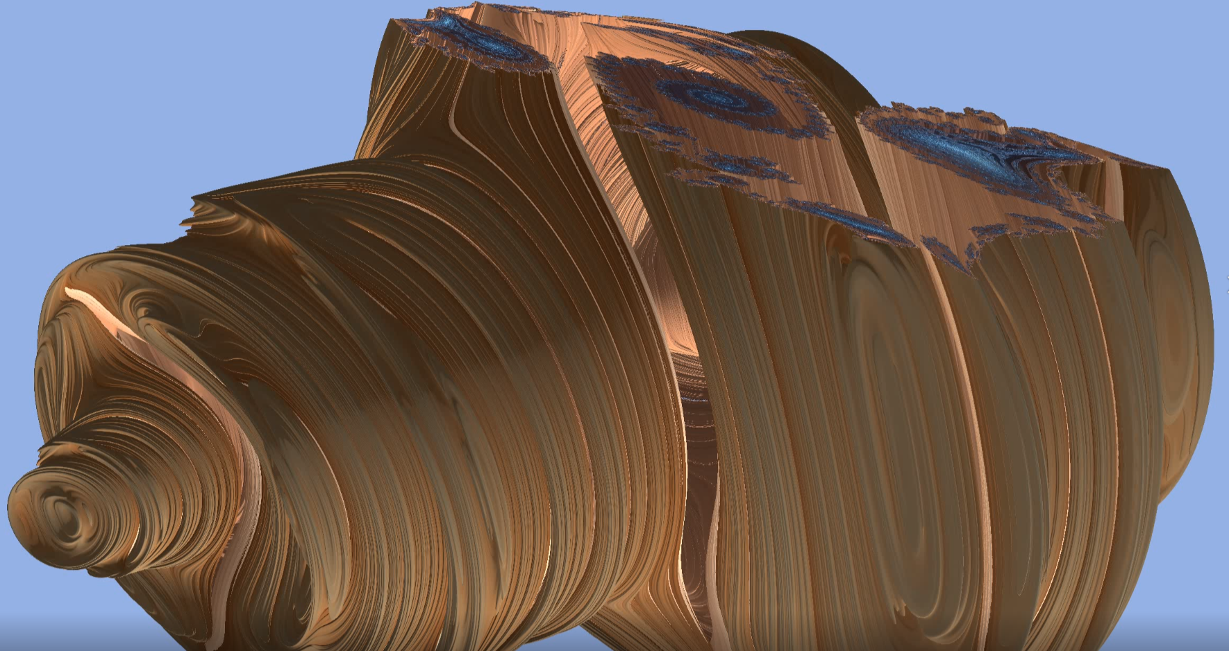
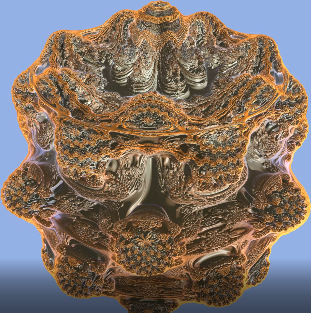
Proceduray’s design choices reflect in its API, which is discussed in this section. Our approach is to show small simplified C++ code snippets to guide the creation of a sample scene containing a triangle plane mesh and several procedural objects (two CSG Pac-men, and two fractals: a 3D Julia Set, and a Mandelbulb). The full source code can be found in https://github.com/dsilvavinicius/Proceduray, implemented and tested on Windows, using Visual Studio 2019. For theory and details about the fractals shader code, please refer to [\citenameda Silva et al. 2021]. Figure 3 shows the sample scene and Figures 4 and 5 show close-ups of a 3D Julia Set cut by different planes and an animated Mandelbulb, respectively.

4.1 Procedural Sample Scene
The core of the sample is in the user class MandelJuliaPacSceneBuilder, which creates everything needed to set the RTPSO up in function build() (Listing 1). This includes Rays, Hit Groups, Geometry, Constant Buffers for communication between host and device, an instance buffer with information fetched using the entries in the Shader Table and the Indexing Rule (Equation 1), the Acceleration Structure, Root Signatures and Shader Table entries.
Each one of the methods called use Proceduray’s API to create the objects needed. buildRays() creates all Ray types and specifies string ids for future queries. This pattern is repeated for almost all scene components. The API expects the miss shader entry point and the Payload, which is a variant for the Shader Compatibility Layer. The sample has a radiance ray type and a shadow ray type (Listing 2).
The API expects a tuple id, internal name, any-hit shader entry point, closest-hit shader entry point, intersection shader entry point to represent a Hit Group, which is added to the scene using addHitGroup(). The entry points can be empty if the Hit Group does not have the associated shaders. Function buildHitGroups() (Listing 3) shows how to add hit groups for the radiance and shadow rays used in the sample. Notice how shadow Hit Groups only needs to define the Intersection Shader (except for the plane, which must use the built-in one).
Geometry can be added to the scene using addGeometry(). Procedural geometry expects an AABB and an instance vector with transformations for proper instance placement in the scene. Triangle meshes expect arrays of vertices and indices, and an instance vector as well. Listings 4 and 5 show the code.
The procedural shaders in the sample scene must access the transformation matrices so they can work at local space instead of world space. This approach simplifies the Intersection Shaders. Those matrices are stored in a buffer, created by the function buildInstanceBuffer() (Listing 6).
The Acceleration structure is created directly from scene geometry, as discussed in Section 3. Thus, the API for this is very straightforward, as can be seen in Listing 7.
4.1.1 Root Signatures and Shader Table Entries
A key idea behind the sample is to express an efficient and flexible way to fetch geometry data using the Acceleration Structure. Efficiency comes from minimizing data on the Local Root Signatures, so fewer resources are needed for the intersection traversal and more parallel work can be done. This is done using the Local Root Signatures data to index the actual geometry on the Global Root Signature. In practical terms, the triangle vertex and index buffers, as well as the instance buffer are in the Global Root Signature. The instance buffer is then indexed by the values contained in the Local Root Signatures.
The Global Root Signature contains the output texture, the acceleration structure, the scene constant buffer, the plane buffers, and the instance buffer. Each entry describes which register will be bound to which resource. Notice how the API needs a type specification for each inline entry. This type is ensured by the Shader Compatibility Layer for all operations involving those components. Listing 8 shows the code.
The sample contains two Local Root Signatures, one for triangles and another for procedural geometry (Listing 9). Type safety is also applied for all types set in the process. The conjunction of the Shader Table and the RTPSO ensures that the correct Root Signature is used for each instance in the Acceleration Structure. Notice the use of method setRootArgumentsType(), which sets the struct type of the data in the Root Signature. The actual values for those types are provided by the Shader Table entries, fetched at traversal time. Those entries contain the indexing data for the instance buffer in the Global Root Signature.
The flexibility comes from the Shader Table entries. They are used to build both the Shader Table and the RTPSO. The Shader Table is responsible for associating Hit groups and Local Root Signature Arguments with the Acceleration Structure, so the indices for the instance buffer in the Global Root Signature can be fetch in the traversal. Listing 10 shows the process. Remember that a Shader Table entry has the format Ray id, Hit Group id, Local Root Signature id, Root Arguments. The most important here is to note how ProceduralRootArguments rootArgs is set to contain the indices for the instance buffer.
5 Conclusion
This paper introduced Proceduray, an engine for real-time ray tracing of procedural geometry. We discussed in detail the problems related to integrating DXR procedural geometry in engines. We also discussed DXR host code in detail, a topic with very scarce references.
This work provides an in-depth example of how to create the host code for a real-time scene with non-trivial procedural objects, such as the Mandelbulb and Julia Sets, using Proceduray. For a full implementation with host and device code, please check the official repository at https://github.com/dsilvavinicius/Proceduray. For details about the device code, please check [\citenameda Silva et al. 2021].
We hope this paper can help developers to use DXR in the context of procedural geometry and can clarify how to develop flexible intersection shaders using Shader Tables. Additionally, we expect it to foment a more open discussion about DXR host code.
Future works include using Proceduray in more applications involving procedural geometry. Particularly, we are interested in supporting efficient ways to represent curved rays ([\citenameVelho et al. 2020, \citenameNovello et al. 2020b, \citenameNovello et al. 2020c, \citenameNovello et al. 2020a]). We also plan to investigate support for Neural Implicits. Finally, we are considering supporting Vulkan [\citenameSellers and Kessenich 2016] in future versions.
References
- [\citenameBenty et al. 2020] Benty, N., Yao, K.-H., Clarberg, P., Chen, L., Kallweit, S., Foley, T., Oakes, M., Lavelle, C., and Wyman, C., 2020. The Falcor rendering framework, 03. URL: https://github.com/NVIDIAGameWorks/Falcor.
- [\citenameCommunity 2018] Community, B. O. 2018. Blender - a 3D modelling and rendering package. Blender Foundation, Stichting Blender Foundation, Amsterdam. URL: http://www.blender.org.
- [\citenameda Silva et al. 2021] da Silva, V., Novello, T., Lopes, H., and Velho, L. 2021. Real-time rendering of complex fractals. In Ray Tracing Gems 2, A. Marrs, P. Shirley, and I. Wald, Eds. TBD, TBD, ch. TBD, TBD.
- [\citenameEpic Games ] Epic Games. Unreal engine. URL: https://www.unrealengine.com.
- [\citenameHaas 2014] Haas, J. K. 2014. A history of the unity game engine.
- [\citenameHaines and Akenine-Möller 2019] Haines, E., and Akenine-Möller, T., Eds. 2019. Ray Tracing Gems. Apress. http://raytracinggems.com.
- [\citenameMarrs et al. 2021] Marrs, A., Shirley, P., and Wald, I. 2021. Ray Tracing Gems 2. TBD.
- [\citenameMcGuire et al. 2019] McGuire, M., Shirley, P., and Wyman, C. 2019. Introduction to real-time ray tracing. In ACM SIGGRAPH 2019 Courses. 1–155.
- [\citenameMicrosoft 2020] Microsoft, 2020. Directx raytracing (dxr) functional spec, 08. URL: https://microsoft.github.io/DirectX-Specs/d3d/Raytracing.html.
- [\citenameMours 2019] Mours, P., 2019. Accelerating cycles using nvidia rtx, 07. URL: https://code.blender.org/2019/07/accelerating-cycles-using-nvidia-rtx/.
- [\citenameNing a] Ning, T. Getting started with directx ray tracing in unity - siggraph 2019. URL: https://youtu.be/DoKOCgNel7E.
- [\citenameNing b] Ning, T. Getting started with directx ray tracing in unity - siggraph 2019. URL: https://on-demand.gputechconf.com/siggraph/2019/pdf/sig940-getting-started-with-directx-ray-tracing-in-unity.pdf.
- [\citenameNovello et al. 2020a] Novello, T., da Silva, V., and Velho, L. 2020. Design and visualization of riemannian metrics. arXiv preprint arXiv:2005.05386.
- [\citenameNovello et al. 2020b] Novello, T., Silva, V., and Velho, L. 2020. Visualization of nil, sol, and sl2 (r) geometries. Computers & Graphics.
- [\citenameNovello et al. 2020c] Novello, T., Silva, V. d., and Velho, L. 2020. Global illumination of non-euclidean spaces. Computers & Graphics 93, 61 – 70. doi:https://doi.org/10.1016/j.cag.2020.09.014.
- [\citenameNVidia 2020] NVidia, 2020. Nvidia dlss unreal engine integration. https://github.com/NvRTX/UnrealEngine.
- [\citenameParker et al. 2010] Parker, S. G., Bigler, J., Dietrich, A., Friedrich, H., Hoberock, J., Luebke, D., McAllister, D., McGuire, M., Morley, K., Robison, A., et al. 2010. Optix: a general purpose ray tracing engine. Acm transactions on graphics (tog) 29, 4, 1–13.
- [\citenameSellers and Kessenich 2016] Sellers, G., and Kessenich, J. 2016. Vulkan programming guide: The official guide to learning vulkan. Addison-Wesley Professional.
- [\citenameSilva and Velho 2019] Silva, V., and Velho, L. 2019. Ray tracing virtual reality in falcor : Ray-vr. Technical Report TR-05-2019, VISGRAF Lab - IMPA. URL: https://www.visgraf.impa.br/Data/RefBib/PS_PDF/tr-05-2019/tr-05-2019.pdf.
- [\citenameUnity 2020] Unity, 2020. Unity startup dxr project. https://github.com/Unity-Technologies/SmallOfficeRayTracing.
- [\citenameUnknown 2020a] Unknown, 2020. Custom dxr shader integration, 07. URL: https://forums.unrealengine.com/development-discussion/engine-source-github/1784862-custom-dxr-shader-integration.
- [\citenameUnknown 2020b] Unknown, 2020. Custom texture2d in an existing shader, 04. URL: https://forums.unrealengine.com/development-discussion/engine-source-github/1741196-custom-texture2d-in-an-existing-shader.
- [\citenameUnknown 2020c] Unknown, 2020. Using a custom intersection shader for ray tracing?, 06. URL: https://answers.unrealengine.com/questions/966354/using-a-custom-intersection-shader-for-ray-tracing.html.
- [\citenameVelho et al. 2020] Velho, L., da Silva, V., and Novello, T. 2020. Immersive visualization of the classical non-euclidean spaces using real-time ray tracing in vr. In In Proceedings of the 46th Graphics Interface.