Peer-to-Peer Localization for Single-Antenna Devices
Abstract.
Some important indoor localization applications, such as localizing a lost kid in a shopping mall, call for a new peer-to-peer localization technique that can localize an individual’s smartphone or wearables by directly using another’s on-body devices in unknown indoor environments. However, current localization solutions either require pre-deployed infrastructures or multiple antennas in both transceivers, impending their wide-scale application. In this paper, we present P2PLocate, a peer-to-peer localization system that enables a single-antenna device co-located with a batteryless backscatter tag to localize another single-antenna device with decimeter-level accuracy. P2PLocate leverages the multipath variations intentionally created by an on-body backscatter tag, coupled with spatial information offered by user movements, to accomplish this objective without relying on any pre-deployed infrastructures or pre-training. P2PLocate incorporates novel algorithms to address two major challenges: (i) interference with strong direct-path signal while extracting multipath variations, and (ii) lack of direction information while using single-antenna transceivers. We implement P2PLocate on commercial off-the-shelf Google Nexus 6p, Intel 5300 WiFi card, and Raspberry Pi B4. Real-world experiments reveal that P2PLocate can localize both static and mobile targets with a median accuracy of 0.88 m.
1. Introduction
Localization service is highly desired in many practical and critical use cases. For example, it can help warehouse keepers find target goods in a messy warehouse, locate medical equipment in an emergency hospital, alert parents when their kids go out of sight in a shopping mall, and remind patients where to find their pill bottles when needed. These use cases call for a new peer-to-peer localization system that should ideally satisfy the following requirements: (i) it should work in a plug-and-play manner without pre-training or pre-deployed infrastructures, as the accurate locations and orientations of pre-deployed infrastructure in warehouses or shopping malls may be unavailable for localization; (ii) it should achieve decimeter-level accuracy with minimal antennas that are affordable to on-body devices, e.g., smartphones carried by warehouse keepers, parents, and patients. More generally, such a technology can enable a variety of applications and be applied seamlessly in our daily lives.
Recent years have witnessed great advances in indoor localization with decimeter-level accuracy through RF technologies (Zhu et al., 2013; Yin et al., 2017; Teng et al., 2013; Shu et al., 2015; Ladd et al., 2005). However, different from what we expect to become a ubiquitous service like GPS in outdoors, current techniques suffer from limitations that prohibit their applications in in-situ peer-to-peer localization scenarios: (i) They require either multiple antennas (Xiong and Jamieson, 2013; Kotaru et al., 2015) or ultra-wide signal bandwidth (Vasisht et al., 2016; Soltanaghaei et al., 2018), which are not available in on-body mobile devices that generally have only a single antenna and limited transmission frequency bandwidth. (ii) They are infrastructure-based (Sen et al., 2013; Sugasaki and Shimosaka, 2017) and require in advance the accurate deployment locations or/and orientations of the pre-deployed access points (APs) to perform triangulation or trilateration. (iii) Some techniques (Bahl and Padmanabhan, 2000; Nistér et al., 2004; Sen et al., 2012; Chen et al., 2017) require expensive and recurring signal fingerprinting or the assistance of IMUs, which suffers from significant errors caused by environment variations or measurement accumulation.
In this paper, we introduce a peer-to-peer indoor localization system, referred to as P2PLocate, that enables a single-antenna device (receiver) to localize another single-antenna device (target) with decimeter-level accuracy. Instead of relying on multiple antennas or pre-deployed infrastructures, P2PLocate employs a single small-formed, ultra-low-cost, and batteryless backscatter tag. The backscatter tag communicates by either reflecting or absorbing signals without emitting any power of its own. In particular, we control the state of the backscatter tag to change the wireless channel and create multipath variations intentionally. The multipath variations are further coupled with user movement to pinpoint the direction of incoming RF signals. Thus, by fusing the direction and range estimates, the receiver can localize the target. More specifically, P2PLocate works as follows: the target device, which is carried by the lost kid, transmits WiFi packets. The backscatter tag, attached to the parent’s body, modulates its information and reflects the WiFi packet. The mobile phone or other wearables with the commodity WiFi chip, which is carried by the parent, serves as the receiver to measure the Channel State Information (CSI) of each WiFi packet from both the remote target device and the backscatter tag and then localizes the target. In contrast to most prior indoor localization systems, P2PLocate can pinpoint the location of any WiFi devices regardless of their antenna numbers, by merely using a single-antenna device and a co-located backscatter tag.
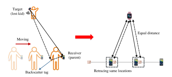
P2PLocate leverages an unseen opportunity with a single-antenna device and a co-located backscatter tag. We illustrate the intuition in Fig. 1. When the receiver and the co-located backscatter tag move, the backscatter tag may retrace the locations of the receiver. The distance between the target and the backscatter tag would be equal to the distance between the target and the receiver when and only when the backscatter tag arrives at a location traveled by the receiver. Based on this observation, P2PLocate can estimate the moving speed of the target relative to the receiver. Thus, by estimating and comparing with the radial speed offered by Doppler effect, P2PLocate can identify the direction of the target relative to the receiver.
To translate the above idea into a practical system, however, is nontrivial due to three main challenges. First, the backscatter signal is weak and typically superimposed with a strong direct-path signal as well as signals reflected from furniture, walls and other nearby clutter. Second, the mobility of the receiver is used to identify the direction information of the target, which fails when the target device is also mobile. Third, due to the existence of Carrier Frequency Offset (CFO), the Doppler shift estimated by using traditional approaches only has absolute values without arithmetic signs, which fails the direction estimation.
To address the aforementioned challenges, our system, P2PLocate, introduces three main innovations that together enable it to achieve decimeter-level accuracy.
-
•
Separating Backscatter CSI. P2PLocate’s first component eliminates the interference from the strong direct-path signal and separates robust backscatter CSI. The backscatter CSI can in turn be used to estimate the time of flight (ToF) and Doppler shift. To do so, P2PLocate leverages the nature of the backscatter modulation that it modulates information by switching its impedance between the reflective and non-reflective state. P2PLocate separates the backscatter CSI by subtracting CSI measurements corresponding to different states while eliminating the effect of significant measurement errors.
-
•
Acquiring full Doppler information and range estimates. The accuracy of ToF estimation is limited by the transmission frequency bandwidth. Instead of fully relying on ToF, P2PLocate fuses it with Doppler shift to achieve fine-grained range estimation. The key insight is that the resolution of Doppler shift, which depends on the signal observation interval, is much fine-grained than the raw ToF estimates. Further, P2PLocate also introduces a two-step algorithm to estimate the full Doppler information, including the absolute value and the arithmetic sign.
-
•
Estimating direction for both static and moving targets. To tackle the target mobility which fails the direction estimation, P2PLocate carefully analyzes the effect of target mobility on direction estimation and proposes a mobility-resilient direction estimation algorithm. Such a design allows P2PLocate to identify the direction of the target no matter it is static or moving.
We prototype P2PLocate based on commercial off-the-shelf devices, including Google Nexus 6p, Intel 5300 WiFi card, and Raspberry Pi B4, and a customized backscatter tag based on FS-Backscatter (Zhang et al., 2016b). We conduct both controlled experiments and field study in two different scenarios, including two different floors of a laboratory and an office building. The evaluation results reveal that P2PLocate achieves an average localization accuracy of 0.88 m, while both transceivers equip with only a single antenna each. The results show approximately a accuracy improvement compared to IMU-assisted solution and are comparable to the state-of-the-art localization system that requires multiple antennas and multiple distributed receivers.
2. System Overview
P2PLocate is a fine-grained peer-to-peer localization system that achieves decimeter-level accuracy. P2PLocate leverages an on-body mobile device and a co-located backscatter tag to enable an individual to localize another individual’s on-body device with no prior infrastructures or fingerprinting. The backscatter tag is ultra-low-cost and battery-free and can be easily embedded into on-body devices. Further, P2PLocate only requires a single antenna on both transceivers and a single-channel measurement. It works both in line-of-sight, through occlusions, and even when both transceivers move. P2PLocate is fully compatible with commercial off-the-shelf devices equipped with WiFi chips.
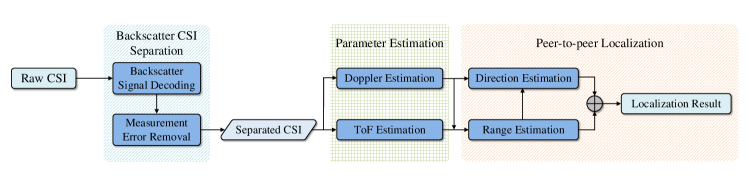
Fig. 2 shows P2PLocate’s three components and its workflow:
-
•
Backscatter CSI Separation: P2PLocate resolves the backscatter CSI based on the backscatter modulation by using the raw CSI measurements that are exposed by commodity WiFi devices (Section 3).
-
•
Doppler and ToF Estimation: P2PLocate estimates ToF and Doppler shift, including the absolute value and the arithmetic sign corresponding to the direct path from the target device to the receiver and the backscatter tag (Section 4).
-
•
Peer-to-peer Localization: P2PLocate estimates the range and direction information of the target device relative to the receiver (Section 5), and then computes the target location by fusing the range and direction estimates.
3. Backscatter CSI Separation
In this section, we describe how P2PLocate can reliably resolve the backscatter CSI at the receiver side. Recall that the main challenge in backscatter CSI extraction arises from the strong interference and significant measurement errors. It complicates backscatter signal detection and reduces the reliability of the backscatter CSI.
3.1. Characterizing Backscatter Communication
Before we describe P2PLocate’s backscatter CSI separation algorithm, we start by introducing the backscatter communication technology. In backscatter networking, the backscatter tag communicates by harvesting power from ambient radio frequency (RF) signals, like TV signals, WiFi signals, LoRa signals, etc., which eliminates the requirement of wires and batteries. In P2PLocate, we use the WiFi-based backscatter to assist peer-to-peer localization. Two features of backscatter communication are particularly relevant to the localization problem.
-
•
The backscatter tags are battery-free, and can communicate merely by leveraging ambient RF signals. It means that once the backscatter tags are embedded into the on-body devices, they do not consume any extra energy from the devices. Therefore, the on-body devices can afford the utilization of backscatter tags to assist localizing the target.
-
•
Any commodity devices with WiFi chips can receive and decode backscatter signals without firmware or hardware modification. The complex channel values of the tags can be extracted since many WiFi radios have the ability to obtain the CSI per WiFi packet. These channel values can be used for localization.
| Acronym | Full name | Acronym | Full name |
|---|---|---|---|
| CSI | Channel State Information | ToF | Time of Flight |
| CFO | Carrier Frequency Offset | STO | Symbol Time Offset |
| SFO | Sampling Frequency Offset | AoA | Angle of Arrival |
| Symbol | Definition | Symbol | Definition |
|---|---|---|---|
| Observed wireless channel at the receiver | Wireless channel without backscatter reflections | ||
| Wireless channel corresponding to backscatter reflections | Observed wireless channel of one subcarrier | ||
| WiFi packet index | P | Multipath profile | |
| Path length change rate | Steering vector | ||
| Subcarrier index | Observed wireless channel corresponding to bit 0 of backscatter information | ||
| Doppler frequency shift | Light speed | ||
| Range estimates from the target to the receiver | Range estimates from the target to the backscatter tag |
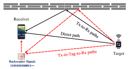
Specifically, WiFi-based backscatter systems enable a low-power backscatter tag to convey bits. Smartphones or other wearables with commodity WiFi chips can receive and decode the backscatter signals. As illustrated in Fig. 3, a backscatter tag communicates with a WiFi device by modulating its wireless channel (Kellogg et al., 2014). In particular, it conveys a sequence of 0 and 1 bits by either reflecting or absorbing the WiFi packets, which changes the wireless channel and causes multipath variation. Mathematically, the wireless channel, , observed on the receiver side for -th packet can be expressed as
| (1) |
where is the wireless channel between the transceiver pair without backscatter reflections, denotes the modulated bits (0 or 1), and is the wireless channel corresponding to the reflections by the backscatter tag, i.e., the multipath variation.
P2PLocate’s first component focuses on separating the backscatter CSI from the interference due to strong direct-path signal. In principle, one could do that by simply subtracting the CSI measurement corresponding to a bit 0 from that corresponding to a bit 1. However, this solution is complicated by two main factors. First, the backscatter signal is weak, which limits the ability to decode backscatter signal and segment packets corresponding to 0 and 1 bits. Second, due to the lack of tight time synchronization between the transceivers, the observed CSI suffers large time-varying phase distortions, which enforces large errors for the direct subtraction approach. The rest of this section describes how P2PLocate addresses these challenges.
3.2. Decoding Backscatter Signal
To separate the packets corresponding to 0 and 1 bits robustly, P2PLocate leverages the property that each WiFi OFDM symbol has multiple subcarriers. The minimum time interval with which the backscatter tag switches its state is larger than the duration of an OFDM symbol. That is, the duration of each bit transmitted by the backscatter tag is greater than the time it takes to transmit a few OFDM symbols. This ensures that different subcarriers of a single OFDM symbol experience the same backscatter state. Thus, P2PLocate can decode the backscatter signal by combing all available subcarriers, which enhances the power of backscatter signals and averages the noise of the CSI measurements. Specifically, for each packet, P2PLocate computes the following summation:
| (2) |
where is the observed CSI of -th subcarrier, and is the total number of subcarriers. Then, similar to (Kellogg et al., 2014), a moving average method is used in where we use a time window with a length of 100 ms to remove the variations in the time domain and normalize the amplitudes.
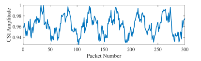
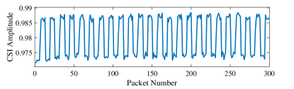
As shown in Fig. 4, the decoded backscatter signal by using single-subcarrier CSI measurements does not have two distinct levels. In contrast, when combining the CSI measurements of all subcarriers, the backscatter signal can be easily decoded.
3.3. Handling the Phase Distortions
Now that we know how P2PLocate decodes backscatter signals, we switch our focus on how to separate the backscatter CSI when diverse phase distortions across packets exist.
Recall that due to hardware impairment, the observed CSIs are mixed with rich measurement errors from various sources inevitably. For example, sampling frequency offset (SFO) and symbol timing offset (STO) introduce a time delay to the ToF estimation. Carrier frequency offset (CFO) results in a constant frequency shift across all subcarriers, which affects the Doppler estimation. Mathematically, for the -th subcarrier of the -th packet, the observed CSI can be expressed as
| (3) |
where is the phase distortion caused by STO and SFO, and is the phase distortion caused by CFO. Next, P2PLocate proceeds to eliminating the effect of CFO, STO, and SFO.
CFO removal. To remove the effect of CFO, P2PLocate leverages the fact that CFO is frequency-independent (Xie et al., 2019a). That is, the phase distortion caused by CFO in every frequency band of each packet is identical. Hence, we can use the phase measurement of any subcarrier as a reference to calibrate other subcarriers by simply subtracting from it. In P2PLocate, the phase measured at the first subcarrier is chosen as the reference.
STO and SFO removal. The phase distortion caused by the STO and SFO is due to the non-synchronized clocks between the WiFi transceivers. Besides, is different from packet to packet, since the STO is time-varying. This time-varying phase distortion prevents P2PLocate from separating backscatter CSI by directly subtracting the CSI measurement corresponding to a bit 0 from that corresponding to a bit 1.
To eliminate the effect of STO and SFO, conventional approaches rely on CSI measurements from either multiple channels or multiple antennas. However, it is inapplicable in peer-to-peer localization where there is only a single antenna and a single channel measurement. Instead, to retain robust backscatter CSI, we carefully analyze the effect of STO and SFO in the multipath profile and propose a novel removal algorithm. The basis of the algorithm is that the multipath profiles of consecutive packets in coherence time should be identical since the consecutive packets travel along the same wireless channel. It is worth noting that the wireless channel consists of two components, i.e., and , as described in Section. 3.1. In particular, within the coherence time, the multipath profile of the packet corresponding to a bit 1 has more peaks, i.e., reflected paths of backscatter tag, than that corresponding to a bit 0. Besides, some peaks of the paths from the target to the receiver might merge with the peaks of the reflected paths of the backscatter tag. Thus, there will be errors if we choose the merged peak and simply shift the multipath profile to align this peak. Instead, P2PLocate estimates the phase distortion difference by calculating the correlation of two multipath profiles, which leverages the entire multipath profile. Specifically, P2PLocate first computes the multipath profile of each packet which will be introduced in Section 4.2. Let and be the multipath profile of one packet corresponding to a bit 1 and one corresponding to a bit 0 in coherence time. P2PLocate calculates the correlation between these two multipath profiles by
| (4) |
where is the length of and , and is the step length we choose in computing the multipath profile. The difference between STO and SFO, named as , can be estimated by finding the maximum of . Therefore, we can compensate for the effect of STO and SFO by
| (5) |
We repeat this procedure for different pairs of WiFi packets and average the estimates to improve the accuracy. Finally, the backscatter CSI can be separated by subtracting CSI corresponding to a bit 1 from compensated CSI corresponding to a bit 0 as
| (6) |
where is the observed CSI corresponding to a bit 1, and represents the CSI corresponding to a bit 0 after STO and SFO compensation.
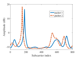
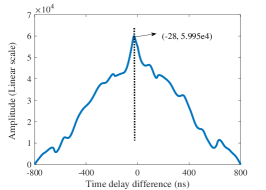
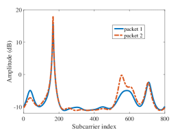
To further illustrate the above algorithm, we collect CSI measurements at 5 GHz frequency band with the backscatter tag switching between reflecting and non-reflecting state. We decode the backscatter signal as described in Section 3.2 and choose two CSI measurements within coherence time, one corresponding to a bit 1 of the backscatter information and the other corresponding to a bit 0. The multipath profiles for the two CSI measurements are shown in Fig. 5(a). There exists a time delay between the peaks of these two multipath profiles, which can be determined by finding the maximum of , as depicted in Fig. 5(b). After removing the effect of STO and SFO, the peaks of two multipath profiles coincide with each other as shown in Fig. 5(c). Note that after removing the difference of phase distortions between consecutive packets, there exists residual errors. We divide all subcarriers into several groups and leverage the SFO phase error compensation algorithms proposed in (Xie et al., 2019a) to remove residual errors.
4. Doppler and ToF Estimation
So far, we have discussed how P2PLocate can separate the backscatter CSI. In this section, we describe how it can estimate the Doppler shift and Time of Flight corresponding to the direct path.
4.1. Doppler Estimation
First, we introduce how P2PLocate can estimate Doppler shift. Note that P2PLocate leverages Doppler shift for fine-grained range and direction estimation. However, it cannot be directly estimated due to the existence of CFO. To address this challenge, P2PLocate leverages both amplitude information of CSI and the user movement and proposes a two-step Doppler estimation algorithm.
Doppler effect. Doppler effect is the frequency change of the signal wave when the transmitter moves relative to the receiver. Let denote the Doppler shift corresponding to the direct path, indicate the center frequency of the signal, and represent the speed of light. The radial speed, i.e., the speed along the direct path, can be expressed as
| (7) |
It is noteworthy that the resolution of Doppler estimation depends on the signal observation interval. For example, at 5 GHz frequency band, a signal observation interval of 1 s corresponds to a resolution of 1 Hz for Doppler estimation, which further corresponds to a resolution of only 0.06 m/s for the path length change rate. Thus, it is fine-grained for range and direction estimation in peer-to-peer localization.
Absolute value estimation. In practice, due to the existence of CFO which appears as Doppler effect, it is infeasible to directly estimate Doppler shift from the observed CSI measurements. To address this, P2PLocate only uses the amplitude information instead of the phase information for Doppler estimation, inspired by prior work (Wang et al., 2015; Venkatnarayan and Shahzad, 2019). Specifically, we first calculate the CSI power, i.e., . Then, the short-term Fourier transform (STFT) is applied to compute the spectrogram of Doppler shift corresponding to each subcarrier. It is worth noting that there has no static paths while the receiver or the transmitter moves. Instead, we leverage the observation that there are reflections with very low power which can be regarded as static paths (Venkatnarayan and Shahzad, 2019). Based on this observation, we can still estimate the Doppler shift while the transmitter and the receiver moves. The signal observation interval is set to 1 s to obtain a resolution of 1 Hz for Doppler estimation as mentioned before. Finally, the radial speed between the receiver and the target can be computed as Eq. (7).
Furthermore, to average the noise and improve the accuracy of speed estimates, we combine the Doppler shift estimated from the CSI measurement of different subcarriers as
| (8) |
Then, we remove the outliers which differ by large variations from the surrounding estimates to obtain the final speed estimates.
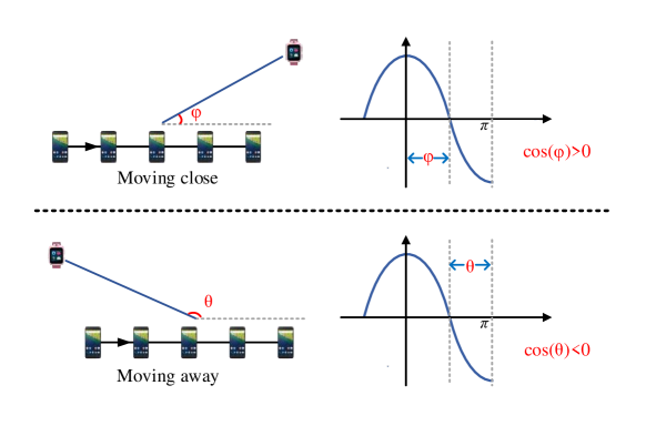
Arithmetic sign estimation. The above approach, however, loses the arithmetic sign of Doppler shift. That is, with only the absolute value of Doppler shift, we have no idea whether the user moves away or close to the target. To address this, P2PLocate leverages the synthetic aperture radar (SAR) created via the user movement. Specifically, according to (Adib and Katabi, 2013), traditional SAR computes the direction of the signal source by applying standard antenna array equation as
| (9) |
where is the consecutive channel measurement, is the wavelength, and is the absolute spatial separation between successive virtual antennas. Note that traditional SAR requires precise locations of virtual antenna for direction estimation. Unfortunately, such information is unavailable. To address this, we carefully analyze the effect of errors in location and observe that we can still track the relative movement, i.e., moving away or close. As illustrated in Fig. 6, when moving close the target, the direction of the target relative to the moving direction of the receiver, i.e., , varies from to , which means . In contrast, when moving away from the target, varies from to , which means . Based on this observation, P2PLocate determines whether the receiver is moving close to or away from the target by estimating the sign of the cosine value. Mathematically, let the ground truth spatial separation be . Thus, if we use a predetermined value, i.e., , to compute the angle, Eq. 9 can be rewrite as
| (10) |
The estimated result is instead of the truth value . In practice, we cannot obtain the exact value of . Fortunately, is positive, as and represent absolute spatial separation. Thus, does not change the arithmetic sign of final estimates. That is, and have the same arithmetic sign, which can still be used to pinpoint the relative movement of the target and the receiver. In P2PLocate, we use the CSI measurements with an interval of 25 ms to synthesize virtual antenna array and set as 2.5 cm, as 1 m/s is a reasonable walking speed of human. It is worth noting that, instead of SAR, P2PLocate introduces novel algorithms to estimate the precise direction of target.
4.2. ToF Estimation
Next, we describe how P2PLocate estimates the ToF, which is used for range estimation. Mathematically, as each OFDM symbol has multiple equally spaced subcarriers, the observed CSI on the receiver can be written in a vector form as . To resolve the multipath signal, we leverage the observation that the number of available subcarriers is larger than that of paths in indoor environments. Therefore, we construct a smoothed CSI matrix as a form of Hankel matrix as
| (11) |
where is an intermediate parameter and we set in P2PLocate. According to (Kotaru et al., 2015; Gong and Liu, 2018), the signal space should be orthogonal to the noise space. Thus, we can apply Singular Value Decomposition (SVD) on the smoothed CSI matrix to obtain the noise space with eigenvalue zero, which is orthogonal to the steering vector , where . Hence, the ToF estimates can be identified by finding the orthogonal projections of as
| (12) |
The peaks of the above equation represent the ToF estimates of the direct path and the reflected paths. Typically, there are usually 2 to 5 dominant paths in indoor environments (Kotaru et al., 2015; Gong and Liu, 2018; Xiong and Jamieson, 2013). To identify the ToF corresponding to the direct path between the transceiver pair, we leverage the intuition that ToF estimates for the direct path will show much smaller variations compared to the reflections from the environment. That is, the direct-path ToF estimate from different packets will be clustered together, while the diameter of each cluster is calculated by the variations in ToF values (Kotaru et al., 2015). Specifically, we use the widely adopted Gaussian Mean clustering algorithm (Kotaru et al., 2015; Gong and Liu, 2018; Soltanaghaei et al., 2018) to eliminate the multipath effect and identify the direct-path ToF estimates. According to (Kotaru et al., 2015), the number of cluster is set as 5 and the mean of the tightest cluster is used as the direct-path ToF estimate.
It is worth noting that P2PLocate only estimates one dimension information, i.e., the ToF. Thus, the computational complexity, which increases exponentially with the number of signal dimensions, is much lower than other localization proposals that estimate parameters from multiple dimensions. Lower computational complexity leads to lower latency for each location estimate in P2PLocate. Furthermore, it is more suitable to deploy P2PLocate on on-body devices, such as smartwatches or smartphones, whose computing power is much lower than a dedicated computer.
5. Peer-to-peer Localization
So far, we have discussed how P2PLocate can estimate the ToF and Doppler shift. In this section, we describe how it can obtain fine-grained range and direction estimation, and then localize the target.
5.1. Range Estimation
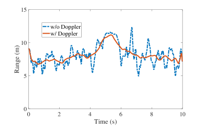
To estimate the range, a nature heuristic is to exploit the ToF information described in Section 4.2. We can compute the range between transceivers by using the ToF value along with the speed of light. However, the accuracy of the estimated range suffers from low resolution of ToF due to the limited signal bandwidth. The blue curve of Fig. 7 shows the range calculated directly from the ToF estimates. The range estimates are fluctuating and thus cannot be directly used for direction estimation and final localization.
To refine the range estimation, P2PLocate leverages the Doppler shift described in Section 4.1, i.e., the path length change rate. Recall that the resolution of path length change rate is 0.06 m/s at 5 GHz frequency band with a signal observation interval of 1 s. It is much fine-grained than ToF estimation, which has an error of a few ns, leading to meters of ranging error. However, Doppler shift is relative while the ToF estimation is absolute. To get the best of both worlds, we incorporate the ToF and the Doppler estimates into a Kalman Filter to refine the range estimation. The red curve of Fig. 7 shows the result after the filter, which is more accurate than the raw estimation.
5.2. Direction Estimation
Next, P2PLocate proceeds to estimating the direction of the target relative to the line formed by the backscatter tag and the receiver. Our key idea to estimate the direction lies in a novel speed estimation algorithm, named virtual path alignment. In this section, we illustrate how P2PLocate can estimate the direction in both cases that the target is moving or remains static.
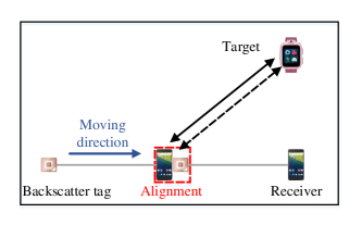
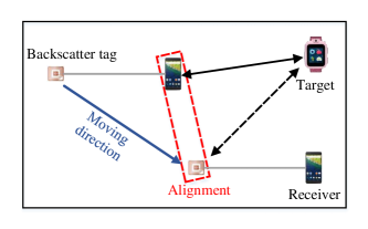
We observe that, in peer-to-peer localization scenarios, the movements of the target and the receiver are relative to each other. That is, we can consider that only the receiver is moving, regardless of whether the target is moving or remains static. As P2PLocate leverages the direct-path information that only depends on the relative locations of the target and the receiver for direction estimation, it can also work in the multipath environments. Note that P2PLocate extracts the direct-path information in Section. 4.2. Based on this observation, without loss of generality, we describe the direction estimation algorithm in the case of static target. Specifically, as the parent carrying the receiver and the backscatter tag moves, there are two cases as shown in Fig 8: (i) 1D case: the moving direction is the same as the line between the receiver and the backscatter tag; (ii) 2D case: the moving direction is different from the line between the receiver and the backscatter tag. Next, we illustrate the direction estimation, first in 1D and then 2D cases.
1D case. As shown in Fig. 8(a), consider a setup in which the on-body backscatter tag and the receiver, carried by the parent, are moving along the line formed by themselves towards the target device, carried by the lost kid. At time , the backscatter tag arrives at the location where the receiver traveled through at time (). By examining the arriving time difference , the parent’s moving speed can be derived as , where is the separation distance between the receiver and the co-located backscatter tag. The value of can be measured a priori. Therefore, with the radial speed offered by Doppler estimation, the angle between the moving direction and the line formed by the target and the receiver can be computed as
| (13) |
Then by continuously aligning the direct-path length corresponding to the receiver and the backscatter tag, we can obtain the real-time speed of the parent along the whole trajectory relative to the lost kid, and thus the real-time direction of the lost kid. However, in 2D case, the above method fails in estimating the moving speed, because the real moving distance is not . To address this, we theoretically analyze the effect of the moving direction on the direction estimation. We verify the moving direction has no effect on the direction estimation.
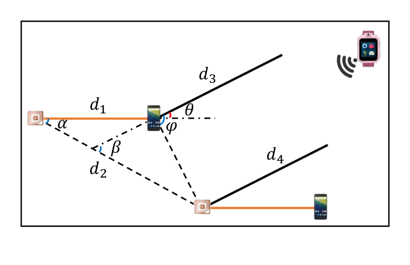
2D case. Specifically, without loss of generality, we consider a setup when the moving direction of the parent is different from the line formed by the receiver and the backscatter tag. As shown in Fig. 10, at at time , the distance between the receiver and the target is . when the receiver and the co-located backscatter tag arrive at at time , the distance between the target and the backscatter tag, represented as , equals to the distance between the target and the backscatter tag, i.e., . Further, as the distance between the target and the receiver is much larger than the moving distance within the time interval of and the distance between the receiver and the backscatter tag, the signals can be considered as parallel incidence. Thus, the direct path should be perpendicular to the line formed by the position of the receiver at time and the position of the backscatter tag at time , i.e., . In particular, we still use the separation distance between the receiver and the co-located backscatter tag, i.e., , to compute the moving speed as
| (14) |
where, and are the ground truth moving distance and the moving speed, respectively. Then, according to the triangle theorem, we can obtain the relation of and as
| (15) |
Based on Eq. 14 and Eq. 15, the cosine value of angle between the transceiver can be estimated as
| (16) |
Note that corresponds to the radial speed and corresponds to the ground truth moving speed. Thus, . Then, we verified that = , which indicates that the moving direction have no effect on the direction estimation. Therefore, we can still obtain the direction of target device even use the ‘wrong’ moving distance. To sum up, the proposed direction estimation methods is applicable to the cases where the parent moves, the kid moves, or the parent and the kid move simultaneously.
Next, we describe how P2PLocate realizes above idea in practice. Recall that in Section. 5.1, the fine-grained distance information has been acquired. Let the range estimates corresponding to the receiver and the backscatter tag be and respectively. The correlation between and can be computed as
| (17) |
The arriving time difference for path alignment between the receiver and backscatter tag can be estimated by finding the peaks of . Finally, the moving speed of the receiver relative to the target can be estimated as . Then, we use a moving window to average the speed estimates, as people move at an even speed during a short interval. The length of the moving window is set as 600 ms. To further improve the accuracy of the speed estimates, we remove the estimates that fail to meet the constraint , as the range of speeds that humans could have in indoor environments, such as malls or museums, is fairly narrow.
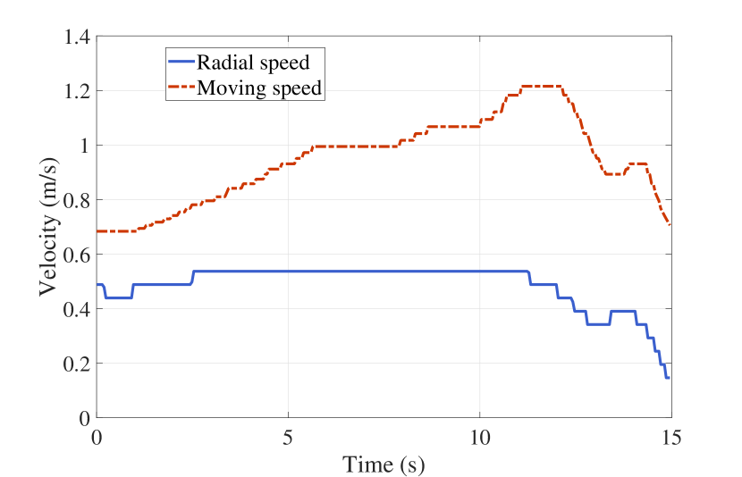
To illustrate this solution, we measure 5 min CSI data of 40 MHz bandwidth at 5 GHz frequency band, when making the target remain static and the receiver move in a predetermined trajectory at the speed varying from 0.8 m/s to 1.2 m/s. The distance between the receiver and the co-located backscatter tag is set as 50 cm. As shown in Fig. 10, the blue curve is the speed estimate using the above method and the red curve is the radial speed by Doppler shift. We can observe that the absolute speed is always larger than the radial speed since the radial speed is a decomposed component of the moving speed. The estimated moving speed is varying from 0.7 m/s to 1.3 m/s, which matches the ground-truth speed.
Finally, as the velocity of the moving target is relative constant, we can localize the target with only on-body single-antenna device by fusing a series of range and direction estimates.
6. Implementation
Our P2PLocate prototype consists of one customized WiFi backscatter tag and a pair of WiFi transceivers, which we describe below.
6.1. Backscatter Tag
We implement the backscatter tag based on the open-source FS-Backscatter hardware (Zhang et al., 2016b). The backscatter tag uses an ADG902 transistor to enable backscatter communication. The transistor is connected to an antenna via an SMA connector and controlled by an Altera STEP-MAX10 FPGA. We program the backscatter tag to transmit data at a bitrate of 1 Kbps without a frequency shift. The bitrate is carefully chosen based on two requirements. First, to ensure at least one entire OFDM symbol experiences the same backscatter state, i.e., the reflecting or non-reflecting state, the backscatter switching period must be larger than two OFDM symbol duration. Second, note that the backscatter CSI is separated by using CSI measurements corresponding to 0 and 1 bits. To ensure the wireless channel remains stable while separating backscatter CSI, the backscatter switching period must be smaller than half the duration of coherence time. To this end, we program the backscatter to transmit data at a bitrate of 300 bps, while the WiFi packet rate of the transmitter is set to 1 kHz.
6.2. Transceiver
Considering the diverse use cases of P2PLocate, we implement the transceiver using three different types of off-the-shelf commodity devices, including Intel 5300 WiFi card representing commonly used APs, Raspberry Pi B4 representing programmable devices and Google Nexus 6p representing on-body devices. All three devices can provide CSI measurement for each WiFi packet.
Intel 5300 WiFi card. We mount Intel 5300 WiFi cards on two Intel NUCs D54350WYKH with a 1.3 GHz Core i5 processor with 4 cores, a 120 GB SSD and an 8 GB RAM, running the Ubuntu 16.0.4 operating system. They are connected to an omni-directional VERT2450 antenna and serve as the transmitter and the receiver, respectively. We use the Linux 802.11n CSI Tool (Halperin et al., 2011) to obtain the CSI measurements of each WiFi packet from both the transmitter and the backscatter tag. Both the transceiver operate on 5 GHz WiFi spectrum due to the firmware limitations mentioned in (Gjengset et al., 2014).
Raspberry Pi B4 and Google Nexus 6p. For real-world deployment, we also employ Google Nexus 6p and Raspberry Pi B4 for evaluation, which are equipped with bcm4358 and bcm43455c0 WiFi chip, respectively. We use the Nexmon CSI Extractor Tool (Schulz et al., 2018) for CSI collection, which allows per-frame CSI extraction for up to 80 MHz bandwidth in both 2.4 GHz and 5 GHz frequency bands. It supports up to nine Broadcom WiFi chips and allows P2PLocate to extract CSI at 64 subcarriers. Each of the real and imaginary parts of CSI for each subcarrier is represented by using 9 or 12 bits for different types of WiFi chips.
6.3. Software
For Intel 5300 WiFi cards and Raspberry Pis, P2PLocate’s localization algorithms are executed locally. For Google Nexus 6p, P2PLocate’s localization algorithms are executed on a workstation with an Intel Core i7-6700K 4.2 GHz CPU and 16 GB RAM. The CSI measurements and IMU sensor data, used for IMU-assisted localization method, are transferred via LTE connections. All algorithms of P2PLocate are implemented using MATLAB in our current prototype.
7. Evaluation
In this section, we conduct extensive experiments in various environments to evaluate the performance of P2PLocate. We first present the experimental setup and then introduce the evaluation results.
7.1. Experimental Setup
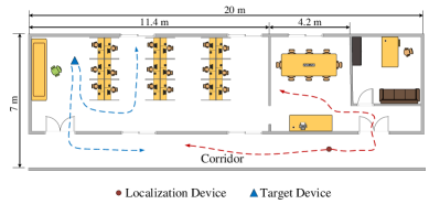
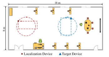
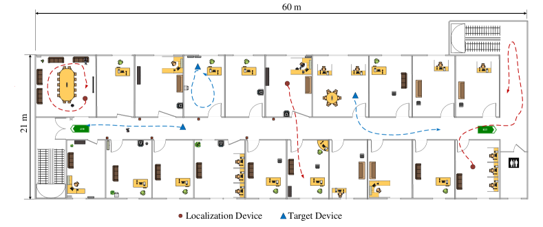
We conduct extensive experiments in two different settings: (i) two different floors of a laboratory measuring 7 m by 20 m and 8 m by 18 m, respectively; (ii) an office area measuring 21 m by 60 m. As shown in Fig. 11, these areas have diverse multipath characteristics and different floor layouts. Besides, during our experiments, there are around 25 and 15 individuals in the laboratory 1 and laboratory 2, respectively. In the office area, there is an average of 3 to 5 individuals in each room and tens of individuals that are walking around. In particular, we deploy four additional receivers equipped with three antennas each to demonstrate the performance of infrastructure-based localization system.
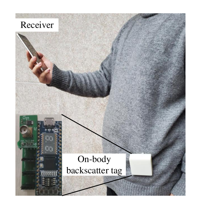
Our experiments are conducted without changing user behaviors. As showed in Fig. 13, one volunteer, serving as the localization end, holds a receiver and a customized backscatter tag is attached to his waist. Another volunteer, serving as the target, puts the transmitter in his pocket. During the experiments, the localization end walks along predefined trajectories with diverse speed. The target either stands still or walks along predefined trajectories to evaluate P2PLocate’s performance for both cases of static and moving target. Note that we test over 200 pairs of predefined trajectories of the receiver and the target in each settings. For brevity, we show only a part of the predefined trajectories in Fig. 11.
Ground truth. We obtain the ground truth via a camera-based tracking system along with the floor plan. Specifically, we first define several trajectories for evaluations. Then, several digital cameras are installed along the predefined trajectories and capture user movement in real time. Finally, to match the location estimates of the camera-based tracking system with the corresponding CSI measurement at that location, we hand-labeled all video date for ground truth by comparing the timestamps with the RF samples.
Baseline. We compare P2PLocate with three localization systems, i.e., IMU-assisted system (Venkatnarayan and Shahzad, 2019), SpotFi (Kotaru et al., 2015) and mdTrack (Xie et al., 2019b). We choose the IMU-assisted system as it best fits our experimental setup, where both the target and the receiver only have a single antenna. Note that other peer-to-peer localization schemes like Chronos (Vasisht et al., 2016) and MonoLoco (Soltanaghaei et al., 2018) require multiple antennas in both the receiver and the target. Additionally, ppNav (Yin et al., 2017) enables peer-to-peer navigation using smartphones, it relies on the wireless fingerprints offered by multiple infrastructures. These systems fail to work properly in our peer-to-peer scenario, and thus we cannot fairly compare our system with them.
We deploy an IMU-assisted localization system as baseline, which integrates wireless signals and IMU data to localize the target. Specifically, since the mobile devices are equipped with IMU sensor, we collect both the CSI measurements and IMU data with time stamps. Then, the IMU data is used to estimate the moving speed of the receiver and keep the rest unchanged compared to P2PLocate. We also compare P2PLocate with two state-of-the-art infrastructure-based localization systems, i.e., SpotFi (Kotaru et al., 2015) and mD-Track (Xie et al., 2019b). We deploy four receivers with three antennas each in the environment. Then, we compute angle of arrival (AoA) of the target by using the algorithm proposed in SpotFi and mD-Track, respectively. Finally, we localize the target by triangulating the AoA measurements across the receivers.
7.2. Overall Accuracy
We start by presenting the overall accuracy of P2PLocate and comparing it with IMU-assisted and infrastructure-based localization methods. We evaluate P2PLocate with both static and moving targets. To calculate localization error, we measure the Euclidean Distance between the estimated locations and the ground truth. Then, we use the Cumulative Distribution Function (CDF) of the localization error to demonstrate the performance.
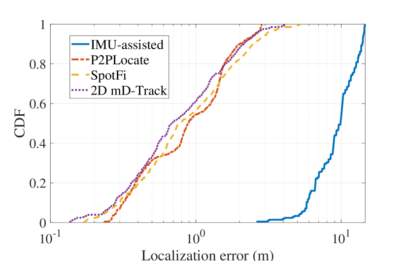
Static target. Fig. 13 shows the localization results in the case where only the localization end moves. P2PLocate achieves a median localization accuracy of 0.88 m compared to 9.9 m for IMU-assisted solution, 0.79 m for SpotFi and 0.68 m for 2D mD-Track. The 90th percentile tail errors are 1.98 m, 13.97 m, 2.43 m and 2.11 m for P2PLocate, IMU-assisted solution, SpotFi, and 2D mD-Track, respectively. Thus, P2PLocate achieves similar accuracy and reliability compared to state-of-the-art infrastructure-based localization systems using only single-antenna on-body devices, making it possible to enable emerging applications mentioned in Section 1.
The primary reason for the large errors for IMU-assisted solution is that the IMU data has large accumulative errors since it requires integration to compute speed. SpotFi and mD-Track achieve more accurate localization results because it leverages spatial information offered by not only multiple receivers but also multiple antennas. However, the accuracy does not improve a lot because it requires the existence of LoS path between the target and all receivers, which limits its usage. To the best of our knowledge, no other localization system achieves decimeter-level accuracy when using only a single antenna.
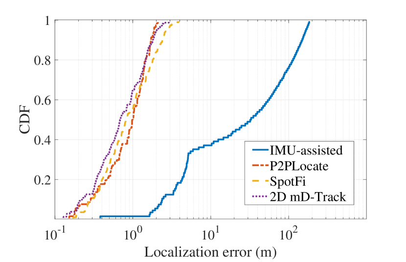
Moving target. Fig. 15 shows the localization results when both the localization end and the target move. P2PLocate achieves a median localization accuracy of 0.98 m, while IMU-assisted solution, SpotFi and 2D mD-Track achieve 33 m, 0.82 m and 0.69 m accuracy, respectively. As seen in the figure, P2PLocate achieves similar results compared to the case that the target remains static, while the IMU-assisted solution suffers larger errors.
The reasons for similar performance for both moving and static cases in P2PLocate are that (i) P2PLocate captures the relative movement of the transmitter and the receiver, and (ii) a mobility-resilient direction estimation algorithm is proposed to eliminate the effect of target’s movement. IMU-assisted solution fails in localizing the target accurately because the onboard IMU sensors can only capture the absolute movement of the localization end instead of the relative movement. Furthermore, the IMU sensors suffer from large accumulative errors.
7.3. Deep Dive into P2PLocate
The previous results show the overall accuracy of P2PLocate for localization. Here, we zoom in on the details.
7.3.1. Doppler Arithmetic Sign Estimation Accuracy of Doppler Shift
First, we evaluate the robustness of Doppler direction estimation. P2PLocate proposes a two-step estimation algorithm to estimate both the absolute value and arithmetic sign of the Doppler shift, which are further used for both range and direction estimation. We use an iRobot Create robot to carry a transmitter and move close or away the receiver from different directions with varying speed. As shown in Fig. 15, P2PLocate yields an average estimation accuracy of 98.6 under different moving speeds. The results demonstrate that P2PLocate can identify whether the parent is moving close or away the lost kid accurately. Overall, P2PLocate demonstrates the ability to estimate fine-grained range and direction information, and thus the final position.
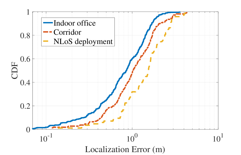
7.3.2. Impact of Environments
We also evaluate the localization accuracy in corridors and None Line-of-Sight (NLoS) environments. To ensure NLoS deployment, the experiments are conducted in locations where the direct path is blocked by obstacles, such as thick walls, wooden furniture, doors and windows. Specifically, the experiments of NLoS deployment are conducted in laboratory 1 and office area as illustrated in Fig. 12. The receiver and the target are asked to be in different rooms, or one in the room and the other in the corridor. As shown in Fig. 17, the median localization accuracy of P2PLocate is 1.02 m and 1.55 m in the corridor and NLoS deployments. The higher localization error rate in these two deployments is due to the nature of the backscatter which is sensitive to the signal power. However, the results are still robust due to our algorithms of backscatter CSI separation.
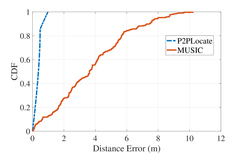
7.3.3. Range Estimation Accuracy
To fully understand P2PLocate’s accuracy in range estimation, we conduct experiments in corridors with different lengths (from 10 m to 70 m). We control the receiver and the co-located backscatter tag to move along a straight line towards the transmitter at a speed of 1 m/s. The signals are transmitted and received at 5 GHz frequency band with 40 MHz bandwidth. We use the traditional MUltiple SIgnal Classification (MUSIC) algorithm (Xiong et al., 2015) that requires multiple CSI measurements across packets for comparison. As shown in Fig. 17, P2PLocate achieves a median accuracy of 0.37 m compared to 3.63 m by only using MUSIC algorithm. With 40 MHz signal bandwidth, it achieves a raw distance resolution of 7.5 meters. The better accuracy of P2PLocate comes from the fusion of ToF and Doppler, which smooths and refines the range estimates.
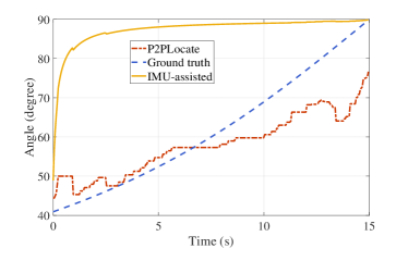
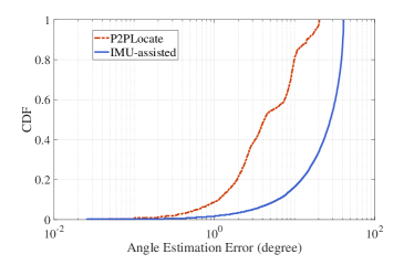
7.3.4. Angle Estimation Accuracy
We also evaluate the angle estimation accuracy of P2PLocate. The experiments are conducted in a hallway by using an iRobot Create robot to control the receiver and the co-located backscatter tag to move in predetermined trajectories, including circles, rectangles, and curves. Fig. 18(a) shows the angle estimation results. From the results, we observe that P2PLocate estimates the angle accurately while the angle estimates by using IMU are highly unreliable. Fig. 18(b) demonstrates that P2PLocate achieves a median accuracy of 4.2 degrees, while the IMU-assisted solution achieves a median accuracy of 28.1 degrees. In P2PLocate, the angle of the target is computed by dividing the moving speed by radial speed of the receiver relative to the target. P2PLocate achieves better performance due to its superior capability in moving speed estimation. While the IMU-assisted method suffers large accumulative error, leading to large error in speed estimation, and thus large error in angle estimation.
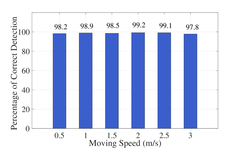
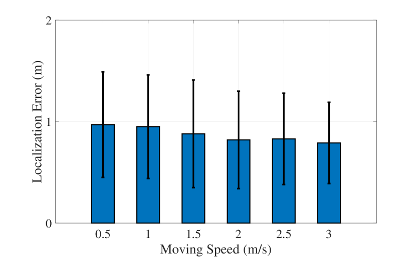
7.3.5. Impact of Moving Speed
As stated in Section 5, the direction of the target device is estimated by computing the moving speed and radial speed. So, we investigate the impact of moving speed on P2PLocate by varying it from 0.5 m/s to 3 m/s with an interval of 0.5 m/s by using an iRobot Create robot. Fig. 20 plots the localization results including both median accuracy and standard deviation. The results demonstrate P2PLocate achieves a median localization accuracy of around 0.88 m, and the accuracy improves with moving speed. The reason is that larger moving speed leads to larger DFS, which may facilitate the range estimation.
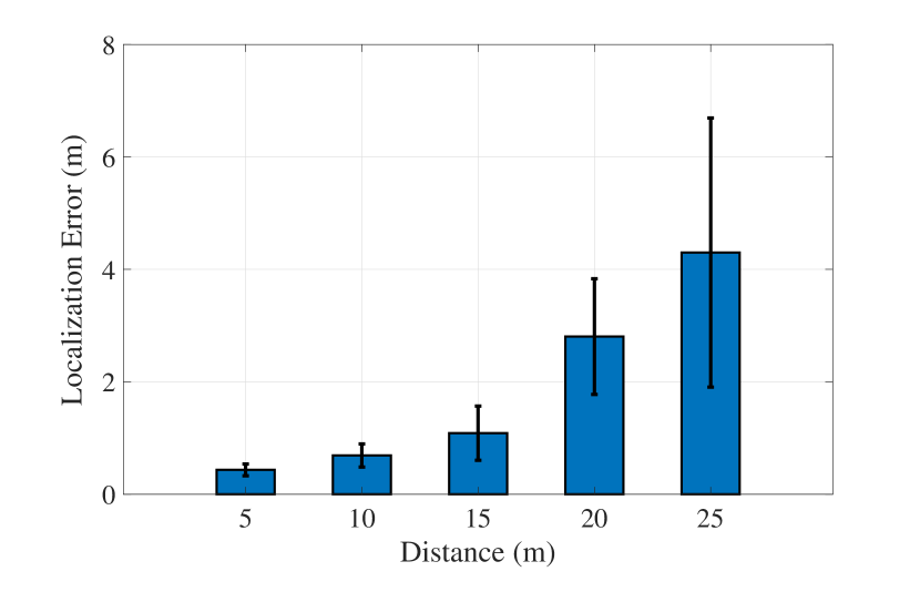
7.3.6. Impact of Distance
Next, we evaluate the impact of the distance between the transmitter and the receiver on localization accuracy. We conduct experiments by varying distance from 5 m to 25 m. Fig. 20 plots the median and standard deviation of localization error against the distance between the transceivers. The median localization error is initially around 0.43 m and increases to at most 4.3 m at 25 meters. In any localization system, the error scales with the distance between the transceivers. The reasons are as follows. First, the signal-to-noise ratio reduces at further distances, which causes the signals reflected by the backscatter tag to become too weak for robust CSI extraction. Second, with the same angle estimation error, larger distance leads to larger localization errors (Kotaru et al., 2015). It is worth noting that these errors are small enough to help patients find their pill bottles or find target good in a messy warehouse.
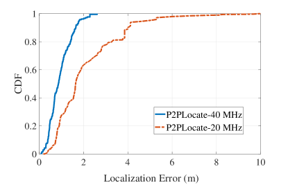
7.3.7. Impact of Channel Bandwidth
Recall that the accuracy of ToF estimation directly depends on signal bandwidth. Therefore, we also evaluate the performance of P2PLocate over 20 MHz signal bandwidth. As showed in Fig. 21, the localization accuracy of P2PLocate reduces over 20 MHz signal bandwidth compared with 40 MHz bandwidth, which is similar to all ToF-based solutions. Yet, it still achieves a median localization accuracy of 1.64 m. This is because we estimate the range by using not only ToF estimates but also Doppler shift, which refines the range estimation and contributes the most to the final stable estimate. In addition, narrower signal bandwidth results in a larger coverage area of P2PLocate since it leads to a longer communication range of the backscatter tags (Xu et al., 2018).
8. Related Work
Indoor localization. Numerous efforts have been devoted to developing indoor localization technologies during the past two decades (Sen et al., 2012; Xiong and Jamieson, 2013; Sugasaki and Shimosaka, 2017; Chen et al., 2017; Khan et al., 2009; Zhang et al., 2020). Most existing works rely on pre-deployed indoor infrastructures to estimate different channel parameters of the direct-path signal for localization, such as ToF (Sen et al., 2013; Vasisht et al., 2016), AoA (Xiong and Jamieson, 2013) or their fusion (Kotaru et al., 2015). These approaches push the localization accuracy to decimeter level by using antenna arrays (Kotaru et al., 2015; Xiong and Jamieson, 2013) or ultra-wide channel bandwidth (Xie et al., 2019a). However, They typically require coordination between multiple APs and are not available in our target use cases. In contrast, P2PLocate enables a single receiver to localize another device and achieves decimeter-level accuracy.
There have been some recent advances in developing peer-to-peer localization systems. SAIL (Mariakakis et al., 2014) achieves a median accuracy of 2.3 m by coupling AoA measured by multiple antennas and ToF measured by a build-in 88 MHz clock of the WiFi card. Chronos (Vasisht et al., 2016) combines all available WiFi frequency bands to achieve decimeter-level accuracy, which may affect ongoing WiFi communications. A recent proposal has demonstrated decimeter-level accuracy with a single AP and single-channel measurement by utilizing the multipath reflections (Soltanaghaei et al., 2018). However, it requires a 3-element antenna array on either the AP side or the target side. In contrast, P2PLocate enables peer-to-peer localization by only relying on the low-profile on-body devices, and achieves sub-meter level accuracy, with only a single antenna on both the transmitter and receiver and a single channel measurement.
Other works employ synthetic aperture radar sensing algorithms to form a virtual antenna array (Wang and Katabi, 2013; Kumar et al., 2014), which can be used to identify the spatial direction of incoming wireless signals. Thus, these proposals can achieve fine-grained localization without hardware modification. However, they need to precisely estimate the location of each virtual antenna and cannot locate moving targets. In contrast, P2PLocate does not need precise antenna position information and is resilient with mobile target. Sen et al. (Sen et al., 2013) fuse motion sensor data with wireless signals for localization, which however suffers large accumulative errors. The IEEE 802.11-2016 (802, 2016) standardized a Fine Time Measurement (FTM) for range estimation, which offers meter-level accuracy. However, it cannot obtain range estimation corresponding to the backscatter and the localization device simultaneously. Many other modalities can also be used to localize objects, such as visible light (Zhang and Zhang, 2016, 2017), acoustic sensing (Mao et al., 2016; Yun et al., 2015), electromagnetic field (Lu et al., 2018), etc. These technologies achieve good performance but require dedicated hardware or are vulnerable to dynamic ambient contexts, making them unsuitable in our targeted applications.
Indoor Human Tracking. Indoor human tracking has attracted a lot of attention over the past a few years (Li et al., 2016; Vasisht et al., 2018; Wang et al., 2016; Wei and Zhang, 2015). Some recent proposals have demonstrated sub-meter level accuracy by using the reflected signals from human bodies. Wi-Vi (Adib and Katabi, 2013) captures reflections from multiple moving objects behind a wall to track them and even identify simple gestures. However, it can only track relative movements and requires dedicated devices. WiDeo (Joshi et al., 2015) achieves fine-grained motion recognition by using software-defined radios, which limits its applications for commodity devices. Some other solutions, such as IndoTrack (Li et al., 2017), Widar2.0 (Qian et al., 2018), and mD-Track (Xie et al., 2019b), leverages Doppler shift for fine-grained human or motion tracking by using commodity devices. However, they require multiple antennas for estimating the direction information of Doppler shift. In comparison, instead of multiple antennas, P2PLocate leverages the human movement along with the CSI power to estimate both the absolute value and arithmetic sign of Doppler shift, which is fully compatible with single-antenna devices.
Backscatter communications. Backscatter communication is considered to be one of the most prominent solutions to provide ubiquitous communication capabilities for low-power Internet of Things. In recent years, there are many improvements in throughput and communication range of backscatter systems (Bharadia et al., 2015; Kellogg et al., 2016; Zhang et al., 2016a; Liu et al., 2013; Song et al., 2020). Liu et al. (Liu et al., 2013) enable communication between two battery-free devices by leveraging ambient TV signals. Other systems (Zhang et al., 2016a; Bharadia et al., 2015; Kellogg et al., 2014) backscatter information on top of WiFi signals and use off-the-shelf WiFi devices as the transceiver. Based on the backscatter communication paradigm, many works focus on using backscatter signals for activity recognition, IoT security or localization (Ryoo et al., 2018; Xiao et al., 2018; Kotaru et al., 2017; Huang et al., 2020). Ryoo et al. (Ryoo et al., 2018) and Xiao et al. (Xiao et al., 2018) use backscatter signals to enable activity recognition when multiple users perform certain motions simultaneously. WiTag (Kotaru et al., 2017) uses backscatter signals and more than three APs to localize backscatter tags based on AoA measurements. In contrast, P2PLocate leverages the multipath variations offered by the backscatter modulation to identify the direction of the target and thus localize the target accurately.
9. Discussion
In this work, we focus on developing an indoor peer-to-peer localization system, which achieves decimeter-level accuracy with single-antenna transceivers. We briefly discuss some limitations and practical issues that have not been directly addressed in this paper.
9.1. Absence of Direct Path
In our design, we assume that there exists a direct path between the receiver and the target, which is a common assumption shared by most localization systems (Soltanaghaei et al., 2018; Xie et al., 2019a; Luo et al., 2019). The evaluation demonstrates that P2PLocate works well in both real-world LoS and NLoS deployments. However, in the extreme case that the direct path is completely blocked, it will fail to localize the target reliably. In the future, we plan to use the information of the reflected paths from as many dimensions as possible, e.g., ToF, AoA and angle of departure (AoD), to localize the target while there exists no direct path.
9.2. Localization Range
Due to the requirement of robust backscatter CSI separation, the system’s localization range in our experiments is limited up to 25 m. It is a common range used in localization systems (Vasisht et al., 2016) and backscatter communications (Zhang et al., 2016a). P2PLocate can work well in most applications mentioned in Section. 1 at this range, e.g., help patients find their pill bottles. To cover a larger space, we can improve the reliability of backscatter CSI separation at further distances by leveraging recent advances in tunnel diodes based backscatter designs (Varshney et al., 2019). Since tunnel diodes only amplify the reflected signal, we believe P2PLocate would also work when using tunnel diodes based backscatter tags.
9.3. Impact of Obstacles
In any localization system (Soltanaghaei et al., 2018; Xie et al., 2019a; Luo et al., 2019), obstacles will affect the performance of P2PLocate. In particular, more obstacles may lead to more serious multipath and affect the accuracy of ToF estimation. Besides, multipath reflections from moving obstacles may cause some adversary effect on Doppler estimation. In our target application scenarios, in addition to the direct path, there are usually 1 to 4 dominant paths reflected by the obstacles (Kotaru et al., 2015; Gong and Liu, 2018; Xiong and Jamieson, 2013). P2PLocate’s current design works well in such environments. To extent P2PLocate in the extreme environments full of obstacles, we may use wider signal bandwidth, e.g., 160 MHz in 802.11ac standard, to enhance the ability of resolving reflections from multiple obstacles. Besides, we may use a larger observation window in Doppler estimation to improve the resolution of resolving Doppler effects caused by mobile obstacles.
9.4. WiFi and Backscatter Interference
In our experiments, we test P2PLocate in the environment where there are tens of WiFi devices within the interference range. As our system builds on commodity WiFi devices, it is resilient to the interference from other WiFi devices as standard WiFi systems, which uses Carrier Sense Multiple Access with Collision Avoidance (CSMA/CA) to avoid interference. To enhance the performance under interference-rich environments, our future implementations of P2PLocate can integrates some recent advances in WiFi interference cancellation technologies (Sen et al., 2011). In addition, the backscatter interference may degrade the performance of P2PLocate which can be alleviated by employing the MAC layer protocol proposed in (Zhang et al., 2017).
10. Conclusion
In this paper, we present the design, implementation, and evaluation of P2PLocate, a peer-to-peer localization technique that leverages on-body devices to enable a single-antenna WiFi device to locate another WiFi device in indoor environments. Real-world evaluations demonstrate that P2PLocate achieves decimeter-level accuracy with only a single channel and a single antenna in both the transmitter and the receiver and without the support of pre-deployed infrastructures or pre-training, allowing its wide-scale adoption due to the plug-and-play manner. By doing so, P2PLocate opens up WiFi-based localization to new applications with size-constrained devices and infrastructure-free environments.
Acknowledgements.
This work was supported in part by the National Key R&D Program of China under Grant 2019YFB180003400, Young Elite Scientists Sponsorship Program by CAST under Grant 2018QNRC001, and National Science Foundation of China with Grant 91738202.References
- (1)
- 802 (2016) 2016. Part 11: Wireless LAN Medium Access Control (MAC) and Physical Layer (PHY) Specifications. IEEE Std 802.11-2016 (Revision of IEEE Std 802.11-2012) (2016), 1–3534.
- Adib and Katabi (2013) Fadel Adib and Dina Katabi. 2013. See through walls with WiFi!. In Proc. ACM SIGCOMM. 75–86.
- Bahl and Padmanabhan (2000) P. Bahl and V. N. Padmanabhan. 2000. RADAR: An in-building RF-based user location and tracking system. In Proc. IEEE INFOCOM. 775–784.
- Bharadia et al. (2015) Dinesh Bharadia, Kiran Raj Joshi, Manikanta Kotaru, and Sachin Katti. 2015. BackFi: High throughput WiFi backscatter. In Proc. ACM SIGCOMM. 283–296.
- Chen et al. (2017) Xi Chen, Chen Ma, Michel Allegue, and Xue Liu. 2017. Taming the inconsistency of Wi-Fi fingerprints for device-free passive indoor localization. In Proc. IEEE INFOCOM. 1–9.
- Gjengset et al. (2014) Jon Gjengset, Jie Xiong, Graeme McPhillips, and Kyle Jamieson. 2014. Phaser: Enabling phased array signal processing on commodity WiFi access points. In Proc. ACM MobiCom. 153–164.
- Gong and Liu (2018) Wei Gong and Jiangchuan Liu. 2018. Sifi: Pushing the limit of time-based WiFi localization using a single commodity access point. Proc. ACM UbiComp (2018), 10:1–10:21.
- Halperin et al. (2011) Daniel Halperin, Wenjun Hu, Anmol Sheth, and David Wetherall. 2011. Tool release: Gathering 802.11 n traces with channel state information. ACM SIGCOMM Computer Communication Review 41, 1 (2011), 53–53.
- Huang et al. (2020) Yong Huang, Wei Wang, Yiyuan Wang, Tao Jiang, and Qian Zhang. 2020. Lightweight Sybil-Resilient Multi-Robot Networks by Multipath Manipulation. In Proc. IEEE INFOCOM.
- Joshi et al. (2015) Kiran Joshi, Dinesh Bharadia, Manikanta Kotaru, and Sachin Katti. 2015. WiDeo: Fine-grained Device-free Motion Tracing using RF Backscatter. In USENIX NSDI. 189–204.
- Kellogg et al. (2014) Bryce Kellogg, Aaron Parks, Shyamnath Gollakota, Joshua R Smith, and David Wetherall. 2014. Wi-Fi backscatter: Internet connectivity for RF-powered devices. In Proc. ACM SIGCOMM. 607–618.
- Kellogg et al. (2016) Bryce Kellogg, Vamsi Talla, Shyamnath Gollakota, and Joshua R Smith. 2016. Passive WiFi: Bringing low power to WiFi transmissions. In USENIX NSDI. 151–164.
- Khan et al. (2009) Usman A Khan, Soummya Kar, and José MF Moura. 2009. DILAND: An algorithm for distributed sensor localization with noisy distance measurements. IEEE Transactions on Signal Processing 58, 3 (2009), 1940–1947.
- Kotaru et al. (2015) Manikanta Kotaru, Kiran Joshi, Dinesh Bharadia, and Sachin Katti. 2015. Spotfi: Decimeter level localization using WiFi. In Proc. ACM SIGCOMM. 269–282.
- Kotaru et al. (2017) Manikanta Kotaru, Pengyu Zhang, and Sachin Katti. 2017. Localizing low-power backscatter tags using commodity WiFi. In Proc. ACM CoNEXT. 251–262.
- Kumar et al. (2014) Swarun Kumar, Stephanie Gil, Dina Katabi, and Daniela Rus. 2014. Accurate indoor localization with zero start-up cost. In Proc. ACM MobiCom. 483–494.
- Ladd et al. (2005) Andrew M Ladd, Kostas E Bekris, Algis Rudys, Lydia E Kavraki, and Dan S Wallach. 2005. Robotics-based location sensing using wireless ethernet. Wireless Networks 11, 1-2 (2005), 189–204.
- Li et al. (2016) Xiang Li, Shengjie Li, Daqing Zhang, Jie Xiong, Yasha Wang, and Hong Mei. 2016. Dynamic-music: Accurate device-free indoor localization. In Proc. ACM UbiComp. 196–207.
- Li et al. (2017) Xiang Li, Daqing Zhang, Qin Lv, Jie Xiong, Shengjie Li, Yue Zhang, and Hong Mei. 2017. IndoTrack: Device-free indoor human tracking with commodity Wi-Fi. Proc. ACM UbiComp (2017), 1–22.
- Liu et al. (2013) Vincent Liu, Aaron Parks, Vamsi Talla, Shyamnath Gollakota, David Wetherall, and Joshua R Smith. 2013. Ambient backscatter: Wireless communication out of thin air. In Proc. ACM SIGCOMM. 39–50.
- Lu et al. (2018) Chris Xiaoxuan Lu, Yang Li, Peijun Zhao, Changhao Chen, Linhai Xie, Hongkai Wen, Rui Tan, and Niki Trigoni. 2018. Simultaneous localization and mapping with power network electromagnetic field. In Proc. ACM MobiCom. 607–622.
- Luo et al. (2019) Zhihong Luo, Qiping Zhang, Yunfei Ma, Manish Singh, and Fadel Adib. 2019. 3D backscatter localization for fine-grained robotics. In USENIX NSDI. 765–782.
- Mao et al. (2016) Wenguang Mao, Jian He, and Lili Qiu. 2016. CAT: High-precision acoustic motion tracking. In Proc. ACM MobiCom. 69–81.
- Mariakakis et al. (2014) Alex T Mariakakis, Souvik Sen, Jeongkeun Lee, and Kyu-Han Kim. 2014. Sail: Single access point-based indoor localization. In Proc. ACM MobiSys. 315–328.
- Nistér et al. (2004) David Nistér, Oleg Naroditsky, and James Bergen. 2004. Visual odometry. In Proc. IEEE CVPR. I–I.
- Qian et al. (2018) Kun Qian, Chenshu Wu, Yi Zhang, Guidong Zhang, Zheng Yang, and Yunhao Liu. 2018. Widar2.0: Passive human tracking with a single Wi-Fi link. In Proc. ACM MobiSys. 350–361.
- Ryoo et al. (2018) Jihoon Ryoo, Yasha Karimi, Akshay Athalye, Milutin Stanaćević, Samir R Das, and Petar Djurić. 2018. Barnet: Towards activity recognition using passive backscattering tag-to-tag network. In Proc. ACM MobiSys. 414–427.
- Schulz et al. (2018) Matthias Schulz, Jakob Link, Francesco Gringoli, and Matthias Hollick. 2018. Shadow Wi-Fi: Teaching smartphones to transmit raw signals and to extract channel state information to implement practical covert channels over Wi-Fi. In Proc. ACM MobiSys. 256–268.
- Sen et al. (2011) Souvik Sen, Romit Roy Choudhury, and Srihari Nelakuditi. 2011. CSMA/CN: Carrier sense multiple access with collision notification. IEEE/ACM Transactions On Networking 20, 2 (2011), 544–556.
- Sen et al. (2013) Souvik Sen, Jeongkeun Lee, Kyu-Han Kim, and Paul Congdon. 2013. Avoiding multipath to revive inbuilding WiFi localization. In Proc. ACM MobiSys. 249–262.
- Sen et al. (2012) Souvik Sen, Božidar Radunovic, Romit Roy Choudhury, and Tom Minka. 2012. You are facing the Mona Lisa: Spot localization using PHY layer information. In Proc. ACM MobiSys. 183–196.
- Shu et al. (2015) Yuanchao Shu, Yinghua Huang, Jiaqi Zhang, Philippe Coué, Peng Cheng, Jiming Chen, and Kang G Shin. 2015. Gradient-based fingerprinting for indoor localization and tracking. IEEE Transactions on Industrial Electronics 63, 4 (2015), 2424–2433.
- Soltanaghaei et al. (2018) Elahe Soltanaghaei, Avinash Kalyanaraman, and Kamin Whitehouse. 2018. Multipath triangulation: Decimeter-level WiFi localization and orientation with a single unaided receiver. In Proc. ACM MobiSys. 376–388.
- Song et al. (2020) Guochao Song, Hang Yang, Wei Wang, and Tao Jiang. 2020. Reliable Wide-Area Backscatter via Channel Polarization. In Proc. IEEE INFOCOM.
- Sugasaki and Shimosaka (2017) Masato Sugasaki and Masamichi Shimosaka. 2017. Robust indoor localization across smartphone models with ellipsoid features from multiple rssis. Proc. ACM UbiComp (2017), 103:1–103:16.
- Teng et al. (2013) Jin Teng, Boying Zhang, Junda Zhu, Xinfeng Li, Dong Xuan, and Yuan F Zheng. 2013. EV-Loc: integrating electronic and visual signals for accurate localization. IEEE/ACM Transactions on Networking 22, 4 (2013), 1285–1296.
- Varshney et al. (2019) Ambuj Varshney, Andreas Soleiman, and Thiemo Voigt. 2019. TunnelScatter: Low Power Communication for Sensor Tags using Tunnel Diodes. In Proc. ACM MobiCom. 1–17.
- Vasisht et al. (2018) Deepak Vasisht, Anubhav Jain, Chen-Yu Hsu, Zachary Kabelac, and Dina Katabi. 2018. Duet: Estimating user position and identity in smart homes using intermittent and incomplete RF-data. In Proc. ACM UbiComp. 1–21.
- Vasisht et al. (2016) Deepak Vasisht, Swarun Kumar, and Dina Katabi. 2016. Decimeter-level localization with a single WiFi access point. In USENIX NSDI. 165–178.
- Venkatnarayan and Shahzad (2019) Raghav H Venkatnarayan and Muhammad Shahzad. 2019. Enhancing indoor inertial odometry with wifi. Proc. ACM UbiComp 3, 2 (2019), 1–27.
- Wang and Katabi (2013) Jue Wang and Dina Katabi. 2013. Dude, where’s my card?: RFID positioning that works with multipath and non-line of sight. In Proc. ACM SIGCOMM. 51–62.
- Wang et al. (2016) Wei Wang, Alex X Liu, and Muhammad Shahzad. 2016. Gait recognition using WiFi signals. In Proc. ACM UbiComp. 363–373.
- Wang et al. (2015) Wei Wang, Alex X Liu, Muhammad Shahzad, Kang Ling, and Sanglu Lu. 2015. Understanding and modeling of WiFi signal based human activity recognition. In Proc. ACM MobiCom. 65–76.
- Wei and Zhang (2015) Teng Wei and Xinyu Zhang. 2015. mTrack: High-Precision Passive Tracking Using Millimeter Wave Radios. In Proceedings of ACM MobiCom.
- Xiao et al. (2018) Ning Xiao, Panlong Yang, Yubo Yan, Hao Zhou, and Xiang-Yang Li. 2018. Motion-Fi: Recognizing and Counting Repetitive Motions with Passive Wireless Backscattering. In Proc. IEEE INFOCOM. 2024–2032.
- Xie et al. (2019a) Yaxiong Xie, Zhenjiang Li, and Mo Li. 2019a. Precise power delay profiling with commodity Wi-Fi. IEEE Transactions on Mobile Computing 18, 6 (2019), 1342–1355.
- Xie et al. (2019b) Yaxiong Xie, Jie Xiong, Mo Li, and Kyle Jamieson. 2019b. mD-Track: Leveraging Multi-Dimensionality for Passive Indoor Wi-Fi Tracking. In Proc. ACM MobiCom. 1–16.
- Xiong and Jamieson (2013) Jie Xiong and Kyle Jamieson. 2013. ArrayTrack: A Fine-Grained Indoor Location System. In USENIX NSDI. 71–84.
- Xiong et al. (2015) Jie Xiong, Karthikeyan Sundaresan, and Kyle Jamieson. 2015. Tonetrack: Leveraging frequency-agile radios for time-based indoor wireless localization. In Proc. ACM MobiCom. 537–549.
- Xu et al. (2018) Chenren Xu, Lei Yang, and Pengyu Zhang. 2018. Practical backscatter communication systems for battery-free Internet of Things: A tutorial and survey of recent research. IEEE Signal Processing Magazine 35, 5 (2018), 16–27.
- Yin et al. (2017) Zuwei Yin, Chenshu Wu, Zheng Yang, and Yunhao Liu. 2017. Peer-to-peer indoor navigation using smartphones. IEEE Journal on Selected Areas in Communications 35, 5 (2017), 1141–1153.
- Yun et al. (2015) Sangki Yun, Yi-Chao Chen, and Lili Qiu. 2015. Turning a mobile device into a mouse in the air. In Proc. ACM MobiSys. 15–29.
- Zhang and Zhang (2016) Chi Zhang and Xinyu Zhang. 2016. LiTell: Robust indoor localization using unmodified light fixtures. In Proc. ACM MobiCom. 230–242.
- Zhang and Zhang (2017) Chi Zhang and Xinyu Zhang. 2017. Pulsar: Towards ubiquitous visible light localization. In Proc. ACM MobiCom. 208–221.
- Zhang et al. (2016a) Pengyu Zhang, Dinesh Bharadia, Kiran Joshi, and Sachin Katti. 2016a. Hitchhike: Practical backscatter using commodity WiFi. In Proc. ACM SenSys. 259–271.
- Zhang et al. (2017) Pengyu Zhang, Colleen Josephson, Dinesh Bharadia, and Sachin Katti. 2017. Freerider: Backscatter communication using commodity radios. In Proc. ACM CoNext. 389–401.
- Zhang et al. (2016b) Pengyu Zhang, Mohammad Rostami, Pan Hu, and Deepak Ganesan. 2016b. Enabling practical backscatter communication for on-body sensors. In Proc. ACM SIGCOMM. 370–383.
- Zhang et al. (2020) Shengkai Zhang, Wei Wang, Ning Zhang, and Tao Jiang. 2020. RF Backscatter-based State Estimation for Micro Aerial Vehicles. In Proc. IEEE INFOCOM.
- Zhu et al. (2013) Xiuyan Zhu, Yuan Feng, et al. 2013. RSSI-based algorithm for indoor localization. Communications and Network 5, 02 (2013), 37.