Large magneto-optical effect and magnetic anisotropy energy in two-dimensional metallic ferromagnet Fe3GeTe2
Abstract
The recent discovery of long-range magnetic orders in atomically thin semiconductors Cr2Ge2Te6 and CrI3 as well as metal Fe3GeTe2 has opened up exciting opportunities for fundamental physics of two-dimensional (2D) magnetism and also for technological applications based on 2D magnetic materials. Due to their unique metallic nature, atomically thin Fe3GeTe2 films exhibit fascinating properties such as Fermi level-tunable Curie temperature, magnetic anisotropy energy and anomalous Hall effect, thus offering valuable applications for, e.g., voltage-controlled 2D spintronics at room temperature. Nevertheless, to exploit these 2D metallic magnets, the mechanisms that control their physical properties should be well understood. In this paper, based on systematic first principle density functional theory calculations, we study two relativity-induced properties, namely, magnetic anisotropy energy (MAE) and magneto-optical (MO) effects, of multilayers [monolayer, bilayer, trilayer, fourlayer and quintlayer] and bulk Fe3GeTe2 and also their connections with the underlying electronic structures of the materials. Firstly, all the considered Fe3GeTe2 structures are found to prefer the out-of-plane magnetization and have gigantic MAEs of 3.0 meV/f.u., being about 20 and 6 times larger than 2D ferromagnetic semiconductors Cr2Ge2Te6 and CrI3, respectively. This gigantic perpendicular anisotropy results from the large magnetocrystalline anisotropy energy (MCE) which is ten times larger than the competing magnetic dipolar anisotropy energy (MDE) which always favors an in-plane magnetization. The giant MCEs are attributed to the large Te orbital density of states near the Fermi level and also to the topological nodal point just below the Fermi level at the K points in the Brillouin zone. Secondly, 2D and bulk Fe3GeTe2 also exhibit strong MO effects with their Kerr and Faraday rotation angles being comparable or even larger than that of best-known MO materials such as PtMnSb, Y3Fe5O12 and Bi3Fe5O12. The features in the Kerr and Faraday rotation spectra are almost thickness-independent although the Kerr rotation angles increase monotonically with film thickness. The strong MO Kerr and Faraday effects are found to result from the large MO conductivity (or strong magnetic circular dichroism) in these ferromagnetic materials. In particular, the calculated MO conductivity spectra are one order of magnitude larger than that of Y3Fe5O12. The calculated MO conductivity spectra are analysed in terms of the symmetry of the band states and dipole-allowed optical transitions at high symmetry , K and K′ points, which further reveal that atomically thin Fe3GeTe2 films with odd layer-number would exhibit anomalous ferrovalley Hall effect. All these interesting findings thus suggest that 2D and bulk ferromagnetic Fe3GeTe2 are promising materials for high density MO and spintronic nanodevices.
I INTRODUCTION
Recent material realization of intrinsic magnetism in atomically thin films of semiconducting Cr2Ge2Te6 [1] and CrI3 [2] as well as metallic Fe3GeTe2 [3, 4] has created numerous fascinating opportunities for two-dimensional (2D) magnetism. Fundamentally, the famous Mermin-Wagner theorem [5] dictates that thermal fluctuation prohibits any long-range magnetic order in isotropic 2D systems at any finite temperature. The discovery of the long-range ferromagnetic order in monolayers (MLs) CrI3 [2] and Fe3GeTe2 [3, 4] thus demonstrates that theories of 2D magnetism need to go beyond the isotropic Heisenberg model. Magnetism at 2D limit is not only highly desirable for the fundamental physics but also for the technological applications ranging from magnetic memories to sensing, to spintronics to novel functionalities based on 2D materials. Among the magnetic 2D materials, few-layer Fe3GeTe2 structures are unique since they are apparently the only ferromagnetic metal that retains the long-range magnetic order down to the 2D limit [7, 6], and thus attract particularly strong attention. For example, owing to its metallic nature, Curie temperature () of trilayer (TL) Fe3GeTe2 was raised from 100 K to 300 K by ionic gating [4], thus offering application potential for voltage-controlled 2D spintronics at room temperature. Furthermore, it was demonstrated theoretically that the magnetocrystalline anisotropy energy (MCE) of ML Fe3GeTe2 is large and also tunable by either tensile strain [8] or electric gating [9]. Strong layer-dependent anoamalous Hall effect in atomically thin Fe3GeTe2 was also predicted recently [10]. Interestingly, unlike 2D semiconductors CrGeTe3 and CrI3 which all have a centrosymmetric crystalline structure, few-layer Fe3GeTe2 with odd number of MLs have the broken inversion symmetry (see Table I below). Consequently, atomically thin Fe3GeTe2 with odd layer-number are expected to exhibit novel properties such as anomalous valley Hall effect [11] and magnetically tunable second-order nonlinear optical responses (e.g., second-harmonic generation and bulk photovoltaic effect) [12].
In this work, we concentrate on two relativity-induced properties of 2D Fe3GeTe2, namely, magnetic anisotropy energy (MAE) and magneto-optical (MO) effects. MAE is the energy needed to rotate the magnetization direction from the easy axis to the hard axis. MAE plays a crucial role in suppressing thermal fluctuation and thus stabilizes long-range magnetic orders in 2D systems. It is also an important factor that characterizes a magnetic material from the application view point. In particular, a thin film with a large perpendicular magnetic anisotropy may find applications in high density magnetic data storage. It has two contributions, namely, the magnetocrystalline anisotropy energy (MCE) and the magnetic dipolar anisotropy energy (MDE). MCE is due to the difference between the relativistic band structures for two different magnetic orientations. On the other hand, MDE originates from the classical magnetic dipole-dipole interaction in the magnetic solid [13, 14]. Interestingly, MDE is determined solely by the crystalline structure and geometric shape of the sample [13, 14]. In a layered material, the MDE always prefers an in-plane magnetization while MCE could favor either an in-plane or the out-of-plane magnetization [15]. Although the MAE of bulk and ML Fe3GeTe2 has been studied both experimentally and theoretically [8, 9, 16], the MAE of atomically thin Fe3GeTe2 films of few-layer thickness has not been reported yet.
MO effects are manifestations of the interplay between magnetism and light in magnetic solids [17, 18]. When a linearly polarized light beam hits a magnetic material, the principal axis of the reflected and transmitted light rotates with respect to the polarization direction of the incident light. The former is called the magneto-optical Kerr effect (MOKE) and the latter is known as the magneto-optical Faraday effect (MOFE). MO effects originate the simultaneous presence of the relativistic spin-orbit coupling (SOC) and spontaneous magnetization in the magnetic solid. The spontaneous magnetization and the SOC result in energy band splitting and thus lead to different refractive indexes for the right- and left-circularly polarized light. As will be discussed in the next section, this magnetic circular dichroism (MCD) gives rise to the MOKE and MOFE. MOKE has been widely applied to study the magnetic properties of thin films and surfaces [18]. Indeed, in Fe3GeTe2 and other 2D ferromagnets, long range magnetic orders were discovered by the MOKE and MCD experiments [4, 3, 2, 1]. Large MOKE and MOFE effects can also be exploited for fabricating high density MO data storage and MO sensors. [19, 20] On the other hand, it is known that 3 transition metal alloys that contain heavy elements such as FePt would have large MO effects due to the large SOC strength on the heavy element atoms [21, 22]. Since Fe3GeTe2 contains heavy Te atoms, bulk and 2D Fe3GeTe2 are expected to have large MO effects. However, there has been no theoretical study on the optical and MO properties of bulk and few-layer Fe3GeTe2.
In this work, therefore, we carry out a systematic first principles density functional theory (DFT) study on the magnetic, electronic, optical and MO properties of monolayer (ML), bilayer (BL), trilayer (TL), fourlayer (FL) and quintlayer (QL) as well as bulk Fe3GeTe2. Indeed, we find that all the considered Fe3GeTe2 structures would exhibit strong MOKE and MOFE especially in the infrared and visible frequency range. Furthermore, we also find that all the structures have a large MAE, being comparable to that of FePt which has the largest MAE among the ferromagnetic transition metals and their alloys. These findings suggest that bulk and few-layer Fe3GeTe2 are promising ferromagnetic materials for nanoscale MO and spintronic devices.
The rest of this paper is organized as follows. In the next section, a brief description of the crystalline structure of the considered Fe3GeTe2 structure as well as the used theoretical methods and computational details is given. In Sec. III, the calculated magnetic properties and electronic band structures as well as the optical and MO properties are presented. The possible origins of the large MAEs are discussed in terms of orbital-decomposed density of states (DOSs) and also the topological features of the band structure near the Fermi level. Also, the peaks in the calculated MO conductivity spectra are analyzed in terms of the symmetry of the energy bands and main interband optical transitions at high symmetry and K points in the Brillouin zone (BZ). Finally, the conclusions drawn from this work are summarized in section IV.
II STRUCTURES AND METHODS
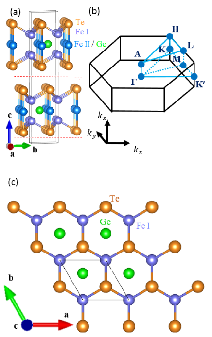
Bulk Fe3GeTe2 forms a layered hexagonal structure with space group P63/mmc (No. 194) and point group , and its experimental lattice constants are Å and Å [23]. Each unit cell contains two weak interacting Fe3GeTe2 MLs [see Fig. 1(a)]. Each Fe3GeTe2 ML consists of five 2D triangular atomic layers where two Te lattices sandwich three ABA-stacked Fe lattices [see Fig. 1(a)] with the Fe and Ge triangular lattices in the central layer forming a honeycomb lattice [see Fig. 1(c)]. The Fe atoms sit on two inequivalent sites, namely, the FeI site with site symmetry and the FeII site with site symmetry [see Fig. 1(a)].
The electronic structure and structural optimization calculations are based on the density functional theory with the generalized gradient approximation (GGA) [24] to exchange-correlation interaction. To accurately describe the structural properties of layered Fe3GeTe2 structures, we have included the DFT-D2 vdW correction of Grimme [25] in the present calculations. The present calculations are performed using the accurate projector-augmented wave (PAW) method [26] implemented in the Vienna simulation package (VASP) [27, 28]. The few-layer Fe3GeTe2 structures are modelled utilizing the slab-superlattice approach with the separations between the neighboring slabs being about 15 Å. A large plane wave cut-off energy of 400 eV is used. For the Brillouin zone integrations using the tetrahedron method [29], -centered -meshes of 16 16 4 and 16 16 1 are used for bulk and few-layer Fe3GeTe2, respectively. Since the experimental structural parameters for few-layer Fe3GeTe2 are unavailable, we have determined theoretically the lattice constants and atomic positions of both bulk and few-layer Fe3GeTe2. The calculated lattice constants are listed in Table I, together with the experimental lattice constants of bulk Fe3GeTe2. Note that the calculated lattice constants of bulk Fe3GeTe2 agree well with the corresponding experimental values (within 0.5 %) (see Table I), suggesting that the structural properties of few-layer Fe3GeTe2 should be well described by the GGA functional [24] plus the DFT-D2 vdW correction [25].
| Bulk | ML | BL | TL | FL | QL | |
|---|---|---|---|---|---|---|
| Point Group | D6h | D3h | D3d | D3h | D3d | D3h |
| (Å) | 3.995 (3.991a) | 4.010 | 4.010 | 4.010 | 4.010 | 4.010 |
| (Å) | 16.73 (16.33a) | |||||
| (Å) | 8.365 | 16.73 | 25.10 | 33.46 | 41.83 |
aReference [23] (X-ray diffraction experiment at 293K).
To determine the MCE, we first perform the total energy calculations for an in-plane magnetization (e.g., along the -axis) and the out-of-plane magnetization (along the -axis). Then, the MCE is given by the total energy difference . Denser -point meshes of 24 24 6 and 32 32 1 are used for bulk and few-layer Fe3GeTe2, respectively. Thus-obtained MCEs are converged within 3 % with respect to the -point meshes used.
Similarly, the MDE is given by the difference in the magnetic dipole interaction energy () between the magnetization along the -axis and along the -axis. For a ferromagnetic system, in atomic Rydberg units, [13, 14]
| (1) |
where the speed of light and the so-called magnetic dipolar Madelung constant
| (2) |
where are the lattice vectors, are the atomic position vectors in the unit cell, and is the atomic magnetic moment (in units of ) on site . In a 2D system, all and are in-plane, and hence the second term in Eq. (2) would vanish for the out-of-plane magnetization. Thus, the for an in-plane magnetization is always lower than that for the out-of-plane magnetization. Consequently, the MDE always prefers an in-plane magnetization rather than the out-of-plane magnetization in 2D magnetic systems [13, 15, 30]. This is a purely geometrical effect and thus MDE is also called the magnetic shape anisotropy energy.
For a solid with at least threefold rotational symmetry and a magnetization along rotational -axis, the non-zero components for the optical conductivity are , , and . We calculate these three independent elements using the linear-response Kubo formula [31, 32, 33]. Thus, the absorptive parts of these elements are given by
| (3) |
| (4) |
where is the photon energy and is the th band energy at point . Summations and are over the occupied and unoccupied bands, respectively. Dipole matrix elements , where denotes the Cartesian component of the dipole operator, are obtained from the relativistic band structure within PAW formalism [34]. The integration is over the whole Brillouin zone using the linear tetrahedron method [35]. The dispersive part of the optical conductivity elements can be obtained from its corresponding absorptive parts using the Kramers-Kronig relations,
| (5) |
| (6) |
where denotes the principal value.
For a bulk magnetic material, the complex polar Kerr rotation angle is given by [21, 36]
| (7) |
However, for a magnetic thin film on a nonmagnetic substrate, the complex polar Kerr rotation is given by [37, 38]
| (8) |
where is the refractive index of the substrate, is the impedance of free space, and stands for the thickness of the magnetic layer. Since few-layer Fe3GeTe2 were usually deposited on a SiO2/Si substrate [4, 3], the refractive index of bulk SiO2 () is used here. Similarly, the complex Faraday rotation angle for a thin film can be written as [39]
| (9) |
where and represent the refractive indices for left- and right-polarized lights, respectively. The refractive indices are related to the optical conductivity and the dielectric function via expression . As a result,
| (10) |
Here the real parts of the optical conductivity can be written as
| (11) |
where . Clearly, and therefore would be nonzero only if and are different. In other words, magnetic circular dichroism is the fundamental cause of the nonzero and hence the MO effect.
| System | () | () | () | () | |||||
|---|---|---|---|---|---|---|---|---|---|
| (1/eV/f.u.) | (f.u.) | (/atom) | (/atom) | (/atom) | (/atom) | (meV/f.u.) | (meV/f.u.) | ||
| bulk | m[001] | 3.25 | 6.29 | 2.41 (0.075) | 1.53 (0.030) | -0.10 (0.001) | -0.04 (-0.016) | 3.37 (-0.086) | 3.28 |
| 4.95a | 2.18b (0.10c) | 1.54b (0.10c) | - | - | 3.4d | - | |||
| m[100] | 6.29 | 2.41 (0.084) | 1.54 (0.050) | -0.10 (0.002) | -0.04 (-0.006) | - | - | ||
| ML | m[001] | 3.24 | 6.27 | 2.44 (0.076) | 1.47 (0.033) | -0.10 (0.001) | -0.04 (-0.018) | 3.00 (-0.32) | 2.68 |
| - | 1.72e | 1.01e | - | - | 2.76e(-0.11e) | 2.0f, 2.7g | |||
| m[100] | 6.28 | 2.43 (0.085) | 1.49 (0.049) | -0.10 (0.003) | -0.04 (-0.007) | - | - | ||
| BL | m[001] | 3.26 | 6.31 | 2.43 (0.076) | 1.54 (0.033) | -0.10 (0.001) | -0.04 (-0.017) | 3.02 (-0.33) | 2.69 |
| m[100] | 6.31 | 2.42 (0.085) | 1.54 (0.052) | -0.10 (0.003) | -0.04 (-0.007) | - | - | ||
| TL | m[001] | 3.34 | 6.31 | 2.43 (0.076) | 1.54 (0.032) | -0.10 (0.001) | -0.04 (-0.017) | 3.20 (-0.33) | 2.87 |
| m[100] | 6.32 | 2.42 (0.085) | 1.55 (0.050) | -0.10 (0.003) | -0.04 (-0.006) | - | - | ||
| FL | m[001] | 3.34 | 6.31 | 2.43 (0.076) | 1.54 (0.032) | -0.10 (0.001) | -0.04 (-0.017) | 3.22 (-0.32) | 2.90 |
| m[100] | 6.32 | 2.43 (0.084) | 1.55 (0.051) | -0.10 (0.003) | -0.04 (-0.007) | - | - | ||
| QL | m[001] | 3.15 | 6.32 | 2.43 (0.076) | 1.54 (0.032) | -0.10 (0.001) | -0.04 (-0.017) | 3.30 (-0.32) | 2.98 |
| m[100] | 6.32 | 2.43 (0.084) | 1.55 (0.051) | -0.10 (0.002) | -0.04 (-0.006) | - | - |
III RESULTS AND DISCUSSION
III.1 Magnetic moments and magnetic anisotropy energy
Since both bulk and few-layer Fe3GeTe2 have been experimentally found to be ferromagnetic [3, 4, 23, 40], we consider only the ferromagnetic configuration in this paper. The calculated spin and orbital magnetic moments of the considered Fe3GeTe2 structures are listed in Table II, together with related previous experimental and theoretical results. First of all, Table II shows that calculated magnetic moments in few-layer Fe3GeTe2 hardly depend on their thickness (i.e., the number of MLs) and also they are very close to that in bulk Fe3GeTe2. This can be expected from the fact that the interlayer interaction is weak in the considered Fe3GeTe2 structures. As mentioned above, in all the considered systems there are two inequivalent Fe sites (FeI and FeII) with different site symmetries (see Fig. 1). Interestingly, Table II shows that in all the considered systems, FeI and FeII have rather different spin magnetic moments, and the difference is nearly as large as 0.9 . For example, the spin magnetic moments of FeI and FeII in bulk Fe3GeTe2 are 2.41 and 1.53 , respectively. In the ionic picture, the valence state of Fe3GeTe2 could be written as (FeII2+)(FeI3+)2Ge4-(Te2-)2 [4] and thus we would expect FeI () and FeII () to have the spin moments of 5.0 and 4.0 , respectively. The fact that calculated spin moments are significantly smaller than these values, supports the notion that these Fe3GeTe2 structures are itinerant ferromagnets [3, 4, 8].
We note that these theoretical spin magnetic moments are in good agreement with the neutron scattering data [41] (Table II). This indicates the validity of the GGA functional used here for describing the magnetic properties of the considered Fe3GeTe2 structures. We can expect that the total magnetic moment in these Fe3GeTe2 structures comes mostly from the Fe atoms, and this would result in a total magnetic moment of 6.35 /f.u. The small difference between this value and the calculated total spin moment is due to the small spin moments of Te and Ge which are antiparallel to that of Fe (see Table II). We also notice that the calculated total magnetic moment is significantly larger than that from the SQUID magnetization measurement (4.95 /f.u.) [40]. This may indicate that the samples used [40] were nonstoichiometric or contained defects and Fe vacancies. Due to the well-known crystal-field quenching, the calculated orbital magnetic moments of the Fe atoms (e.g., 0.076 /Fe for FeI and 0.033 /Fe for II in bulk Fe3GeTe2) are much smaller than the spin magnetic moments. The averaged calculated orbital moment of the Fe atoms is 0.06 /Fe, being smaller but in the same order of magnitude as that (0.10 /Fe) from the XMCD measurement [42]. It is known that the GGA and LDA functionals would give rise to too small orbital moments by up to 40 % (see, e.g., [44, 43] and references therein). Nonetheless, these discrepancies between the experiment and theory can be largely removed by including the so-called orbital polarization correction in the electronic structure calculations (see, e.g., [44, 43] and references therein). Interestingly, Te orbital magnetic moments are comparable to Te spin magnetic moments and furthermore depend strongly on the magnetization direction (Table II). This is because the SOC in Te atoms is much stronger than in Fe and Ge atoms.
We present the calculated magnetic anisotropy energies () in Table II. By definition (), a positive value indicates an out-of-plane magnetization easy axis [i.e., the perpendicular magnetic anisotropy (PMA)]. Strikingly, Table II shows that all the considered Fe3GeTe2s structures have a very large PMA, being 3.0 meV/f.u. or 1.0 meV/Fe. These values not only are several times larger than that of 2D ferromagnetic semiconductors Cr2Ge2Te6 (0.1 meV/f.u.) [15] and CrI3 (0.5 meV/f.u.) [30] but also are comparable to that of heavy metal magnetic alloys such as FePt (2.75 meV/Fe) [45], which is known to have the largest MAE among the transition metal alloys. This large PMA would strongly suppress the magnetic fluctuations in these 2D materials and thus result in a higher ferromagnetic ordering temperature () than 2D ferromagnetic semiconductors CrI3 [2] and Cr2Ge2Te6 [1]. We note that the calculated MAE (2.9 meV/f.u.) of ML Fe3GeTe2 is in good agreement with the RMCD experimental data (2.0 meV/f.u.) [4]. The largeness of the PMA plus its electric tunability [4] suggests that 2D ferromagnetic metallic Fe3GeTe2 would have promising applications in high-density magnetic data storage and other spintronic devices.
Table II indicates that the MAE per f.u. increases slightly as one moves from ML to BL and then TL. However, the MAE per f.u. remains unchanged as the film thickness is further increased, e.g., to that of FL and QL (Table II). As mentioned before, the MAE consists of two competing contributions, namely, the MCE, which prefers PMA, and MDE, which always favors an in-plane magnetization. The MDE in 2D Fe3GeTe2 is in the same magnitude as that in 2D CrI3 and Cr2Ge2Te6. However, the magnitude of the MCE in 2D Fe3GeTe2 is nearly ten times larger than that of the MDE. This results in a gigantic MAE in 2D Fe3GeTe2. Note that these values are nearly three orders of magnitude larger than that of ferromagnetic Fe and Ni ( 4 eV/f.u.) [46]. Bulk Fe3GeTe2 has an even larger MAE of 3.28 meV/f.u., simply because its MDE is much smaller than that in 2D Fe3GeTe2 (Table II). We notice that only one previous study, based on the local density approximation (LDA), on the MDE has been reported. [8] Nevertheless, the calculated MDE for ML Fe3GeTe2 in Ref. [8] is nearly three times smaller than the present calculations (Table II). This is mainly because the LDA spin magnetic moments reported in [8] are significantly smaller than the present GGA calculations (see Table II).
Table II also shows that while the spin magnetic moments are generally independent of the magnetization orientation, the orbital magnetic moments change significantly as the magnetization is rotated, e.g., from [001] to [100]. In particular, the Te orbital moment in ML Fe3GeTe2 gets reduced by nearly 60 % when the magnetization is rotated from [001] to [100], while that of FeI increases by about 12 % (Table II). This may suggest some correlation between the MCE and the anisotropy in the orbital magnetization. Indeed, a previous perturbative theory analysis showed that in elemental transition metal MLs, the easy axis is along the direction in which the orbital moment is largest [47]. This was supported by the ab initio calculations for Fe monolayers imbedded in noble metals [13]. Interestingly, the orbital magnetic moments on heavy element Te atoms (which have the largest SOC) in all the considered Fe3GeTe2 structures with the perpendicular magnetization are much larger than that for an in-plane magnetization, thus indicating a possible connection with the strong PMA in these systems. Nevertheless, Table II shows that the Fe orbital moments in these Fe3GeTe2 structures are larger for an in-plane magnetization than for the perpendicular magnetization, indicating that the perturbative theory analysis for transition metal monolayers [47] may not be wholely applicable to the present ternary compounds.
III.2 Electronic structure
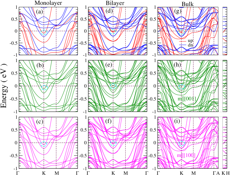
To understand the calculated magnetic and optical properties of the Fe3GeTe2 materials, we present the calculated electronic band structures. The band structures of ML, BL and bulk Fe3GeTe2 are displayed in Fig. 2, and that of TL, FL and QL Fe3GeTe2 in Fig. S1 in the supplementary material (SM) [48]. Since the band structures of bulk and ML Fe3GeTe2 have already been reported in several previous papers [4, 8] and are also rather similar to that of TL, FL and QL Fe3GeTe2 due to the weak interlayer interaction, here we only summarize the salient features of the calculated band structures.
First of all, all the considered Fe3GeTe2 structures are metallic with multiple Fermi surface pockets (Fig. 2 and Fig. S1 in the SM [48]) and hence a large density of states (DOS) at the Fermi level () (Table II). In all the considered systems, there are many hole Fermi surface pockets centered at the point and many electron Fermi surface pockets centered at the K point in the BZ (Figs. 2 and Fig. S1 in the SM). Secondly, because bulk Fe3GeTe2 contains two MLs per unit cell and also the interlayer interaction is weak, the band structure of BL Fe3GeTe2 [Figs. 2(d), 2(e) and 2(f)] are almost identical to that of bulk Fe3GeTe2 [Figs. 2(g), 2(h) and 2(i)]. The band structure of ML Fe3GeTe2 is very similar to that of BL Fe3GeTe2 (Fig. 2) except that the number of the bands is only half of that for the BL. Similarly, the band structures of TL, FL and QL Fe3GeTe2 are overall nearly the same as that of the BL except with the increased number of bands (Fig. S1 in the SM).
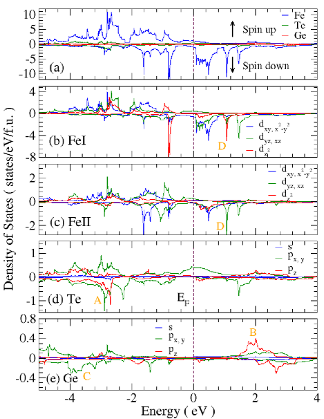
Next, we present the total as well as site-, orbital-, and spin-projected DOS spectra of bulk and 2D Fe3GeTe2 in Figs. 3 and 4 as well as Figs. S2 and S3 in the SM [48]. Figure 3 shows that for bulk Fe3GeTe2, the lower valence bands ranging from -5.0 to -2.2 eV result mainly from the hybridization among Fe , Ge , and Te -orbitals. The upper valence bands and lower conduction bands (from -2.2 to 1.0 eV) are dominated by Fe -orbitals together with minor contributions of Te -orbitals around the Fermi level. Furthermore, Figs. 3(b) and 3(c) show that spin-splitting of Fe bands is large, being more than 1 eV and thus indicating strong intra-atomic exchange interaction in bulk Fe3GeTe2. Interestingly, the local DOS spectra for the FeI and FeII sites are rather different, being consistent with the rather different magnetic moments on these sites (Table II). These differences are caused by their different local environments (coordination number and site symmetry). For example, the main spin-down FeI DOS peak is very sharp and is located at -0.8 eV [Fig. 3(b)] while the main spin-down FeII DOS peak is rather broad and is centered at 0.4 eV [Fig. 3(b)]. This is because there is no ligand atom lying above or below FeI [Figs. 1(a) and 1(c)] and thus FeI orbitals form a rather localized narrow band. In contrast, there is one Te atom sitting right above (or right below) the FeII atom [Figs. 1(a)]. Thus, FeII - and Te -orbitals hybridize and pushes FeII -orbital dominated antibonding band above the Fermi level [Fig. 3(c)].
| 0 | |||
| 0 | |||
| 0 | |||
| 0 | |||
| 0 | |||
| 0 |
Let us now discuss the possible origin of the large MCE in the Fe3GeTe2 systems in terms of the Fe -orbital decomposed DOS spectra in, e.g., Fig. 3. Accoring to perturbation theory analysis, the occupied and empty states near the Fermi level are coupled by the SOC and thus make most important contributions to the MCE [55]. Moreover, for the same spin channel, the SOC matrix elements and prefer the out-of-plane anisotropy, while , , and favour an in-plane anisotropy [56]. The ratios of these matrix elements are : : : : = 4 : 1 : 1 : 3 : 1. [56] Figure 3(b) shows that FeI and orbitals dominate FeI -orbital decomposed DOS spectra in spin-up and spin-down channels, respectively. Consequently, the SOC matrix elements and would make dominating contributions to the MCE, thereby giving rise to the large PMA in bulk Fe3GeTe2. For the FeII sites, the situation is more complicated [Fig. 3(c)]. In addition to the prominent orbitals, there are the pronounced orbital in both spin channels and also the prominent spin-down orbitals. Consequently, there are competing contributions to the MCE from the SOC matrix elements of and , which prefers the PMA, and , which favors an in-plane magnetization. However, since the ratios of these matrix elements are : : : = 4 : 1 : 1 : 3, we believe that FeII atoms would make positive contributions to the PMA although they may be much smaller than FeI atoms.
Figures 3 and 4 show that there are pronounced occupied and unoccupied -orbital DOSs from heavy Te atoms in the vicinity of . To examine the possible contribution of these -orbital states to the MCE, following [56] we derive the SOC matrix elements in the basis of orbitals, which are listed in Table III. Among the nonzero SOC elements, we find that prefers the out-of-plane magnetization but favors an in-plane magnetization. Furthermore, prefers an in-plane magnetization while has no preference. Unlike that for orbitals [56], the expectation values of all nonzero elements are identical. Interestingly, Fig. 3 and 4 show that the Te and make a prominent contribution to the spin-up DOSs near the Fermi level. Since prefers the perpendicular anisotropy and also Te atoms have a much stronger SOC than Fe atoms, the large MCE found in bulk and 2D Fe3GeTe2 may result mainly from the presence of of pronounced Te -orbital DOSs near the Fermi level.
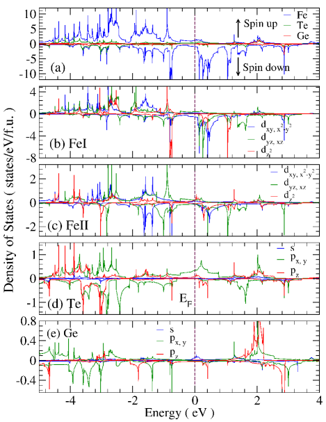
The site-, orbital- and spin-projected DOS spectra of ML Fe3GeTe2 are shown in Fig. 4. All the features of the DOS spectra are similar to that of bulk Fe3GeTe2 (Fig. 3). One pronounced difference is the appearance of FeII orbital dominated peaks near -3.0 eV in the lower valence bands. This can be attributed to the lack of the interlayer coupling because there is no Fe3GeTe2 ML above and below it. The absence of the hybridization among FeII orbitals from neighboring MLs (via Te orbitals) makes FeII orbitals localized and the corresponding band narrow. On the contrary, the peaks of FeI orbitals in bulk and ML Fe3GeTe2 are nearly the same because no ligand atom sits along the direction. The site-, orbital- and spin-projected DOSs of BL and TL Fe3GeTe2 are displayed in Figs. S2 and S3 in the SM [48], where the spectral features fall in between that of ML and bulk Fe3GeTe2.
Finally, we notice a topological nodal point just below at the K point in the scalar-relativistic band structure of bulk Fe3GeTe2 [Fig. 2(g)]. This nodal point extends along the K-H line, and thus forms a topological nodal line. [49] Interestingly, for the perpendicular magnetization, this nodal line becomes split by a large band gap of 60 meV when the SOC is switched-on [Fig. 2(h)]. This results in the upper band being pushed upwards nearly above at the K point and the lower band moving downwards [Fig. 2(h)]. Furthermore, as reported before [49], these SOC-split bands have very large Berry curvatures with opposite signs near the nodal points, thus leading to the large observed anomalous Hall effect in bulk Fe3GeTe2. [49] Here we want to emphasize that this gap-opening at the nodal point also lowers the total band energy. On the other hand, these nodal points remain gapless when the magnetization is in-plane and hence the total band energy would remain much unchanged. Clearly, this would give rise to a significant contribution to the large MCE in bulk Fe3GeTe2 (see Table II). We notice that all 2D Fe3GeTe2 structures except ML Fe3GeTe2 have such a nodal point at the K point [see Fig. 2 and Fig. S1 in the SM]. Therefore, we may conclude that to some extent, the large MCE found in bulk and 2D Fe3GeTe2 also originate from the gap-opening of the topological nodal point at the K point in these structures. We also notice that in ML Fe3GeTe2, although there is no such a nodal point, the top valence band at the K point is lowered by 19 meV when the magnetization is out-of-plane [Fig. 2(b)] but goes up by 9 meV when the magnetization becomes in-plane. Clearly, such band movements due to the presence of the SOC and the change of magnetization direction would also contribute significantly to the large MCE in ML Fe3GeTe2.
III.3 Optical and magneto-optical conductivity
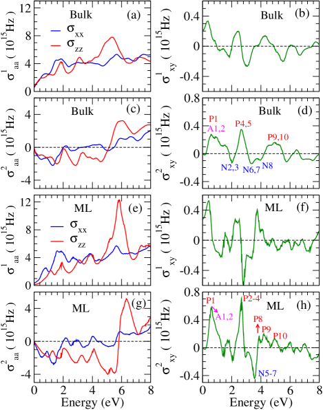
We present the calculated optical and MO conductivity tensors for bulk and ML Fe3GeTe2 in Fig. 5, and also for BL and TL as well as for FL and QL Fe3GeTe2 in Figs. S4 and S4 in the SM [48], respectively. First of all, we can see that all spectra are rather similar. This similarity is due to the weak interlayer interaction in these materials. Such behaviour has also been reported in other 2D magnetic materials such as few-layer CrI3 [30] and Cr2Ge2Te6 [15]. Therefore, below we will analyze only the main features in the optical and MO conductivity spectra of ML and bulk Fe3GeTe2 in detail as representatives of these materials.
Figures 5(a) and 5(e) show that the diagonal elements of the optical conductivity and differ significantly. Since the () is the linear optical response of the materials to an in-plane electric field polarization (out-of-plane electric field polarization ), such difference indicates a large optical anisotropy. This can be expected for 2D or quasi-2D materials [15, 30]. Specifically, the absorptive part of the diagonal element () for bulk Fe3GeTe2 (Fig. 5(a)) is larger than in the low-energy region of 0.0-3.0 eV, but becomes smaller than in the high-energy region of 3.0-6.0 eV. Compared to that of bulk, ML Fe3GeTe2 has a similar difference between and . Nevertheless, as expected, such difference gets slightly enhanced, because ML Fe3GeTe2 is a truly 2D material. We notice that this optical anisotropy can be further understood in terms of the calculated orbital-projected DOS spectra. Note that the and ( and ) states can only be excited by () polarized light while the states can be excited by both. Figures 3 and 4 indicate that the upper valence bands stem mainly from Fe as well as Ge and Te orbitals. In the energy region between -3.0 and 0.0 eV, the overall weight of Fe orbitals (excited by ) is slightly larger than that of Fe orbital (excited by ), thus leading to the slightly higher peaks of in the photon energy region below 3.0 eV [Figs. 5(a) and 5(e)]. Further, broad peaks of Te DOS in the energy range from -1.0 to 1.0 eV [Figs. 3 and 4(d)] also contribute to the higher peaks of below 3.0 eV. On the other hand, significant FeII and Te states appear at lower valance bands from -5.0 to -3.0 eV. This would explain the increase of () above 4.4 eV. Interestingly, among all considered structures, ML Fe3GeTe2 has a particularly sharp Te peak [see Figs. 4(c) and 4(d)] due to the lack of interlayer coupling, as described above. This results in the largest optical anisotropy in ML Fe3GeTe2.
The calculated real () and imaginary () parts of the off-diagonal optical conductivity elements are displayed in Figs. 5(b) and 5(b) (d) for bulk Fe3GeTe2 and in Figs. 5(f) and 5(h) for ML Fe3GeTe2. First of all, we note that in the DC-limit (), is actually the anomalous Hall conductivity (AHC). The AHCs calcuated this way are 233 S/cm, 312 S/cm, 241 S/cm and 287 S/cm for bulk, ML, BL, and TL Fe3GeTe2, respectively. The AHC value for bulk Fe3GeTe2 agrees quite well with the experimental AHC value of 360 S/cm [57] and also previous theoretical one of 287 S/cm [58]. Secondly, as expected, the overall features in the spectra for bulk and ML Fe3GeTe2 are similar. For example, for both structures, the spectra oscillates significantly with several high peaks. Prominent peaks occur mostly between 0.0 and 4.4 eV and beyond 4.4 eV, the magnitude of get significantly reduced, indicating weak magnetic circular dichroism. Specifically, for ML Fe3GeTe2 has pronounced positive peaks at 0.4 eV and 3.8 eV as well as well as a negative peak at 2.8 eV [Fig. 5(f)]. On the other hand, for ML Fe3GeTe2 has large positive peaks at 0.6 eV and 2.6 eV as well as a large negative peak at 3.6 eV [Fig. 5(h)]. In comparison, the spectra of bulk Fe3GeTe2 have peak positions and shapes being rather similar to that of ML but with significantly reduced magnitudes [Figs. 5(b) and 5(d)].
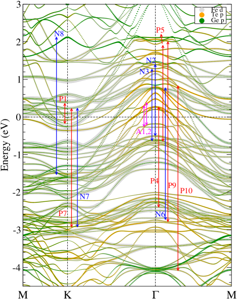
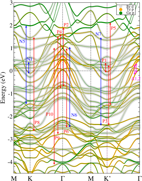
Equations (3), (4) and (11) indicate that the absorptive parts of the optical conductivity elements (, , , ) are directly related to the dipole-allowed interband transitions. This allows us to further understand the origin of the prominent peaks in the optical spectra in terms of the band state symmetries and dipole selection rules of the considered materials here. To this end, we perform a symmetry analysis on the band states and dipole selection rules at high symmetry and K points, as described in the supplementary note 1 in the SM [48]. The derived dipole selection rules are listed in Tables S2 and S3, and the calculated optical transition matrix elements are given in Tables S4 and S5. As mentioned before, few-layer Fe3GeTe2 with an odd number of MLs have the broken inversion symmetry and thus the K′ and K points are not equivalent. Therefore, for ML Fe3GeTe2, we include the K′ point in our symmetry analysis as well. Figures 6 and 7 depict the orbital-projected relativistic band structures of bulk and ML Fe3GeTe2, respectively. We label the main dipole-allowed optical transitions on high symmetry points and K of bulk Fe3GeTe2 in Fig. 6 and also on high symmetry points , K and K′ for ML Fe3GeTe2 in Fig. 7. Based on the calculated transition matrix elements (Tables S4 and S5) and the derived selection rules (Tables S2 and S3), we assign the peaks in the absorptive part of the magnetic-optical conductivity [see Figs. 5(d) and 5(h)] to the main optical transitions near the high symmetry points in Figs. 6 and 7, as indicated by red, blue and magenta symbols and arrows.
We can see from Figs. 6 and 7 that both bulk and ML Fe3GeTe2 have major optical transitions in the energy range from -4.0 eV to 2.0 eV. Interestingly, we find that in this energy range, significant optical transitions would occur only from Fe orbital dominated states which hybridize with Te and Ge orbitals. This results from a direct impact of the strong SOC of heavy elements on the MO effects [59]. Thus, we could also link the main transitions to the calculated DOS spectra presented in the previous section. For example, peak P9 of of bulk Fe3GeTe2 [Fig. 5(d)] originates mainly from an optical transition from the valence states at -3.0 eV to the conduction states at 2.0 eV [Fig. 6], which coincides with the Te peak A to the Ge peak B in Figs. 3(d) and 3(e), respectively. Similarly, peak P10 of bulk Fe3GeTe2 [Fig. 5(d)] originates mainly from an optical transition from -4.0 eV to 0.8 eV [Fig. 6], which coincides with the Ge peak C to the FeI and FeII peak D from Figs. 3(b) and 3(e). Such connection can also be seen in ML Fe3GeTe2 since the DOS spectra from the two structures are similar. Furthermore, we show that the considerable hybridization of Fe orbitals with orbitals of heavy elements in the vicinity of the point in the energy range from around -0.2 eV to 0.2 eV also contribute to the first prominent peak in all the considered Fe3GeTe2 structures. We indicate two of such transitions as a representative by magenta arrows in Figs. 6 and 7.
Importantly, the main optical transitions would reveal not only the effect of orbital hybridizations but also the impact of crystalline symmetry and the SOC. First let us look into the effect of SOC-lifted degeneracies. Figures 6 and 7 show that pairs of right- and left-circular dipole-allowed transitions appear, such as peaks P7 and N7 in Fig. 6 for bulk Fe3GeTe2 and also peaks P6 and N6 in Fig. 7 for ML Fe3GeTe2. As explained in the supplementary note 1 [48], lifted degeneracies would lead to different irreducible representations (irreps) and thus difference in the optical transitions due to left- and right-circularly polarized light. From Table S4 and S5 we could directly observe the magnetic circular dichroism by sign and value differences of the transition matrix elements. Second, we examine the effect of the crystalline symmetry. Figure 7 indicates that optical transitions of ML Fe3GeTe2 sometimes come in pairs at the K and K′ point, e.g., peaks N1 and P1 as well as peaks N5 and P5. This results from the inversion symmetry breaking which leads to an interchange of irreps between the K and K′ point. With the inclusion of the SOC and the spontaneous exchange field due to the intrinsic magnetization, ML Fe3GeTe2 could be a possible ferrovalley material [11]. From Table S5 in the SM [48], we can see the transition energy () to be different for transitions P1 and N1. However, in the absence of ferromagnetism, the dipole-allowed transitions would still be of opposite chirality but with the same due to the broken inversion symmetry. The large difference of 0.13 eV in is thus an indication of possible strong ferrovalley effect in few-layer Fe3GeTe2 containing odd number of MLs. Nevertheless, the spectra from different few-layer structures (Fig. 5 as well as Figs. S4 and S5) are similar. This suggests that although the broken inversion symmetry in the odd-layer structures affects the transition matrix elements at the K and K′ point, it does not change the magneto-optical spectrum significantly. Finally, it should be emphasized that the crucial factor for the large MO conductivity in these structures is the orbital hybridization between the magnetic (Fe) atoms which introduce magnetization and heavy elements (Te) which bring about strong SOC. [22]
III.4 Magneto-optical Kerr and Faraday effects
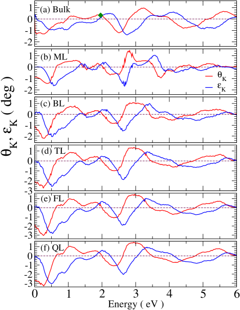
Finally, we plot the calculated MOKE and MOFE spectra as a function of photon energy in Fig. 8 and 9, respectively. Figures 8 and 9 show that for all the few-layer structures of Fe3GeTe2, the patterns of the MOKE and MOFE spectra look similar to that of bulk Fe3GeTe2 [Fig. 8(a) and Fig. 9(a)], especially the Kerr and Faraday rotation spectra of BL, TL, FL and QL Fe3GeTe2. As for the optical conductivity spectra, this similarity of the MO spectra among all the considered structures is due to the weak interlayer coupling in these Fe3GeTe2 systems.
Figure 8 also shows that bulk and few-layer Fe3GeTe2 all exhibit large negative Kerr rotations above 1.0 ∘ in the low energy region below 0.4 eV. In particular, the Kerr angles of FL and QL Fe3GeTe2 are larger than 3.0 ∘ at 0.3 eV. As photon energy further increases, the negative Kerr rotations decrease monotonically and become positive between 0.6 eV and 1.0 eV. Then they all peak at around 1.0 eV and stay positive until photon energy of around 2.0 eV. The positive peaks near 1.0 eV are rather prominent and can reach 1.0 ∘ in TL, FL and QL Fe3GeTe2 (Fig. 8). The Kerr rotation spectra then have a negative peak of -1.0 ∘ again at around 2.5 eV and become positive again as photon energy increases beyond 2.6 eV. They all have a positive pronounced peak at around 3.0 eV except bulk and ML Fe3GeTe2 which have the positive peak at 3.2 eV and 2.8 eV, respectively. Interestingly, the Kerr ellipticity spectra of all the structures have two large negative peaks at around 0.5 eV and 2.6 eV, respectively. MOKE experiments were carried out on a 340-nm thick sample using 633 nm HeNe laser (photon energy 1.96 eV). We note that the measured Kerr angle of 0.33∘ [3] is compared well with our calculated Kerr angle of bulk Fe3GeTe2 [see Fig. 8(a)].
To investigate the potential applications of the Fe3GeTe2 systems in, e.g., MO devices, we now compare the magnitudes of Kerr rotation angles to several popular MO materials. Let us start with 3 transition metals and their alloys. We notice that bcc Fe metal has a Kerr rotation of -0.5∘ at 1.0 eV, hcp Co metal has a Kerr rotation of -0.42∘ at 5.0 eV, and fcc Ni metal has a Kerr rotation of -0.25∘ at 4.0 eV [18, 21, 32]. Clearly, the calculated Kerr rotation angles of few-layer and also bulk Fe3GeTe2 are generally larger than that of elemental 3 transition metals. In particular, the magnitudes of both the Kerr rotation angle and ellipticity of all the considered Fe3GeTe2 structures are larger than 1.0∘ at around 2.5 eV. They are also comparable or even larger than the MOKE in 3 transition metal alloys with heavy elements such as Pt and Bi which have the strong SOC. [22] For example, famous MO transition metal alloys such as FePt, CoPt and PtMnSb have Kerr rotation angles ranging from 0.4∘ to 0.5∘ [21, 60]. Nevertheless, thin film MnBi has a record-high Kerr rotation of 2.3∘ at 1.84 eV [63], which is comparable to or smaller than that of TL, FL and QL Fe3GeTe2 in the infra-red frequency range (within 1.0 eV) (see Fig. 8).
For further comparison, let us examine famous magnetic semiconductors with good MO properties. Ferromagnetic semiconductors Y3Fe5O12 and Bi3Fe5O12, which have been widely used in spintronic research, have Kerr rotation angle of -0.12∘ at 4.8 eV and -1.21∘ at 2.4 eV, respectively [61, 59]. For diluted magnetic semiconductors Ga1-xMnxAs, a Kerr rotation of 0.4∘ near 1.8 eV was reported [62]. Excitingly, layered ferromagnetic semiconductors CrI3 and Cr2Ge2Te6 were recently thinned down to just one or two monolayer with the ferromagnetic order retained at low temperatures [2, 1]. Moreover, TL Cr2Ge2Te6 and TL CrI3 were predicted to have large Kerr rotation of 0.7∘ near 2.8 eV and 1.0∘ at 1.3 eV, respectively [15, 30]. Overall, in comparison to these famous MO semiconductors, the MOKE in bulk and ML Fe3GeTe2 are comparable and in particular, TL, FL and QL Fe3GeTe2 exhibit stronger MOKE.
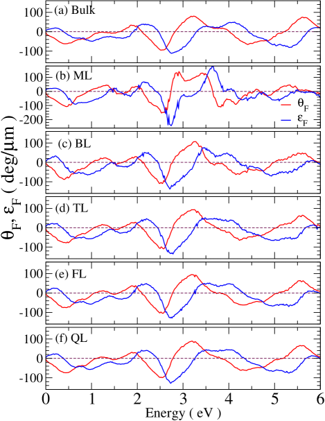
Remarkably, from Fig. 9, we can observe large positive (negative) peaks of value 82 (-97) deg/, 142 (-156) deg/, 109 (-111) deg/, and 95 (-111) deg/ at 2.55 (3.0) eV for bulk, ML, BL, and TL Fe3GeTe2, respectively. For comparison, MnBi thin films are known to possess the largest Faraday rotation angle of 80 deg/ at 1.77 eV [39, 63]. The widely used semiconductor Y3Fe5O12 possesses a Faraday rotation of 7.2 deg/ at 3.9 eV [59]. With the substitution of Y by heavy element bismuth, Bi3Fe5O12 can show a large Faraday rotation angle of 51.2 deg/ at 3.7 eV [59]. We notice that recently discovered 2D ferromagnetic semiconductors Cr2Ge2Te6 and CrI3 have Faraday rotation angles of 120 deg/ [15] and of at most 108 deg/ [30, 38], respectively. Clearly, bulk and 2D Fe3GeTe2 reported here have relatively large Faraday rotation angles. The outstanding MO properties of the considered Fe3GeTe2 systems suggest their promising applications for nanoscale MO sensors and high density MO data-storage devices.
Finally, we notice that MO Faraday rotation spectra of bulk and 2D Fe3GeTe2 (Fig. 9) are similar to their MO Kerr rotation spectra (Fig. 8). This may be expected since Eqs. (7), (8) and (10) indicate that all these MO spectra are more or less proportional to the MO conductivity (). Indeed, the large MOKE and MOFE in bulk and few-layer Fe3GeTe2 stem from their large MO conductivity (i.e., strong magnetic circular dichroism). For example, overall, the MO conductivity of bulk and 2D Fe3GeTe2 (Fig. 5 as well as Figs. S4 and S5 in the SM [48]) is about 20 times larger than Y3Fe5O12 and also 2 times larger than Bi3Fe5O12 [59]. They are also around 2 times larger than bulk and 2D CrI3 [30].
IV CONCLUSIONS
Summarizing, we have investigated two relativity-induced properties, namely, magnetic anisotropy energy (MAE) and magneto-optical (MO) effects, of ML, BL, TL, FL and QL as well as bulk Fe3GeTe2, and also their connections with the underlying electronic structures of the materials, based on systematic first principle DFT calculations. First of all, we find that all the considered Fe3GeTe2 structures prefer the out-of-plane magnetization and have gigantic MAEs of 3.0 meV/f.u., being about 20 and 6 times larger than 2D ferromagnetic semiconductors Cr2Ge2Te6 and CrI3, respectively. These MAE values are also comparable to that of FePt, which is known to have the largest MAE among the magnetic transition metals and their alloys. This gigantic perpendicular anisotropy results from the large relativity-induced MCE of 3.32 meV/f.u., which is ten times larger than the competing classical MDE of 0.3 meV/f.u., which favors an in-plane magnetization (Table II). The giant MCEs can be attributed to the presence of significant Te orbital DOS in the vicinity the Fermi level and also to some extent, to the topological nodal point just below the Fermi level at the K points in the Brillouin zone in these materials. This strong PMA thus stabilizes the long-range ferromagnetic order in 2D Fe3GeTe2 at temperatures higher than that in 2D Cr2Ge2Te6 and CrI3.
Secondly, we also find that 2D and bulk Fe3GeTe2 exhibit strong MO effects with the calculated Kerr and Faraday rotation angles being comparable or even larger than that of best-known bulk MO materials such as PtMnSb, Y3Fe5O12 and Bi3Fe5O12. In particular, all the Fe3GeTe2 structure are predicted to have large Kerr rotation angles of 1.0∘ at 3.0 eV and FL and QL Fe3GeTe2 have Kerr rotation angles as large as 3.0∘ at 0.25 eV (Fig. 8). Furthermore, ML Fe3GeTe2 has a Faraday rotation angle of -156 deg/m, which is three times larger than that of famous MO oxide Bi3Fe5O12. The shape and position of the features in the Kerr and Faraday rotation spectra are almost thickness-independent though the Kerr rotation angles increase slightly with the film thickness. The strong MO Kerr and Faraday effects are found to result from the large MO conductivity (i.e., strong magnetic circular dichroism) in these ferromagnetic materials. In particular, the calculated MO conductivity spectra are one order of magnitude larger than that of Y3Fe5O12. The calculated MO conductivity spectra are analysed in terms of the symmetry of the band states and dipole-allowed optical transitions at high symmetry , K and K′ points, which also reveal that atomically thin Fe3GeTe2 films with odd layer-number would exhibit anomalous ferrovalley Hall effect. We notice that our calculated MAE values for bulk and ML Fe3GeTe2 agree well with the corresponding experimental values and our predicted Kerr angle of bulk Fe3GeTe2 at 1.96 eV is in good agreement with the measured one. Also, the DC-limit of the real part of the calculated MO conductivity of bulk Fe3GeTe2 agrees well with the measured AHC. ALL these interesting findings therefore indicate that 2D and bulk ferromagnetic Fe3GeTe2 may find valuable applications for high density MO and spintronic nanodevices.
ACKNOWLEDGMENTS
The authors acknowledge the support from the Ministry of Science and Technology and the National Center for Theoretical Sciences (NCTS) of The R.O.C. The authors are also grateful to the National Center for High-performance Computing (NCHC) for the computing time.
References
- [1] C. Gong, L. Li, Z. Li, H. Ji, A. Stern, Y. Xia, T. Cao, W. Bao, C. Wang, Y. Wang, Z. Q. Qiu, R. J. Cava, S. G. Louie, J. Xia, and X. Zhang, Discovery of intrinsic ferromagnetism in two-dimensional van der Waals crystals, Nature 546, 265 (2017).
- [2] B. Huang, G. Clark, E. Navarro-Moratalla, D. R. Klein, R. Cheng, K. L. Seyler, D. Zhong, E. Schmidgal, M. A. McGuire, D. H. Cobden, W. Yao, D. Xiao, P. Jarillo-Herrero, and X. Xu, Layer-dependent ferromagnetism in a van der Waals crystal down to monolayer limit, Nature 546, 270 (2017).
- [3] Z. Fei1, B. Huang, P. Malinowski1, W. Wang, T. Song, J. Sanchez1, W. Yao, D. Xiao, X. Zhu, A. F. May, W. Wu,D. H. Cobden, J.-H. Chu, and X. Xu, Two-dimensional itinerant ferromagnetism atomically thin Fe 3GeTe2, Nat. Mat. 17, 778 (2018).
- [4] Y. Deng, Y. Yu1, Y. Song, J. Zhang, N. Z. Wang, Z. Sun, Y. Yi,Y. Z. Wu, S. Wu, J. Zhu, J. Wang, X. H. Chen, and Y. Zhang, Gate-tunable room-temperature ferromagnetism in two-dimensional Fe3GeTe2, Nature 563, 94 (2018).
- [5] N. D. Mermin and H. Wagner, Absence of ferromagnetism or antiferromagnetism in one- or two- dimensional isotropic Heisenberg models, Phys. Rev. Lett. 17, 1133 (1966).
- [6] M. Gibertini, M. Koperski, A. F. Morpurgo, and K. S. Novoselov, Magnetic 2D materials and heterostructures, Nat. Nanotechnol. 14, 408 (2019).
- [7] K. S. Burch, D. Mandrus, and J.G. Park, Magnetism in two-dimensional van der Waals material, Nature 563, 47 (2018).
- [8] H. L. Zhuang, P. R. C. Kent, and R. G. Hennig, Strong anisotropy and magnetostriction in the two-dimensional Stoner ferromagnet Fe3GeTe2, Phys. Rev. B 93, 134407 (2016).
- [9] Y.-P. Wang, X.-Y. Chen, and M.-Q. Long, Modifications of magnetic anisotropy of Fe 3GeTe2 by the electric field effect, Appl. Phys. Lett. 116, 092404 (2020).
- [10] X. Lin and J. Ni, Layer-dependent intrinsic anomalous Hall effect in Fe3GeTe2, Phys. Rev. B 100, 085403 (2019).
- [11] W.-Y. Tong, S.-J. Gong, X. Wan, C.-G. Duan, Concepts of ferrovalley material and anomalous valley Hall effect, Nat. Comms 7, 13612 (2016).
- [12] V. K. Gudelli and G.-Y. Guo, Antiferromagnetism-induced second-order nonlinear optical responses of centrosymmetric bilayer CrI3, Chin. J. Phys. 68, 896 (2020).
- [13] G.-Y. Guo, W. M. Temmerman, and H. ebert, First-principles determination of the magnetization direction of Fe monolayer in noble metals, J. Phys.: Condens. Matter 3, 8205 (1991).
- [14] J. C. Tung, and G.-Y. Guo, Systematic ab initio study of the magnetic and electronic properties of all 3 transition metal linear and zigzag nanowires, Phys. Rev. B 76, 094413 (2007).
- [15] Y. Feng, S. Wu, Z.-Z. Zhu, and G.-Y. Guo, Large magneto-optical effects and magnetic anisotropy energy in two-dimensional Cr2Ge2Te6, Phys. Rev. B 98, 125416 (2018).
- [16] S. Y. Park, D. S. Kim, Y. Lin, J. Hwang, Y. Kim, W. Kim, J.-Y. Kim, C. Petrovic, C. Hwang, S.-K. Mo, H.-j. Kim, B.-C. Min, H. C. Koo, J. Chang, C. Jang, J. W. Choi, and H. Ryu, Controlling the Magnetic Anisotropy of the van der Waals Ferromagnet Fe3GeTe2 through Hole Doping, Nano Lett. 20, 95, (2020).
- [17] P. M. Oppeneer, Chapter 1 Magneto-optical Kerr Spectra, pp. 229-422, in Handbook of Magnetic Materials, edited by K. H. J. Buschow. Elsevier, Amsterdam, (2001).
- [18] V. Antonov, B. Harmon, and A. Yaresko, Electronic structure and magneto-optical properties of solids, Springer Science & Business Media, (2004).
- [19] M. Mansuripur, The Principles of Magneto-Optical Recording, (Cambridge University Press, Cambridge, 1995).
- [20] J. P. Castera, in Magneto-optical Devices, Vol. 9 of Encyclopedia of Applied Physics, edited by G. L. Trigg (Wiley-VCH, New York, 1996), p. 133.
- [21] G.-Y. Guo, H. Ebert, Band-theoretical investigation of the magneto-optical Kerr effect in Fe and Co mulitlayers, Phys. Rev. B 51, 12633 (1995).
- [22] G.-Y. Guo, H. Ebert, On the origins of the enhanced magneto-optical Kerr effect in ultrathin Fe and Co multilayers, J. Magn. Magn. Mater. 156, 173 (1996).
- [23] H.-J. Deiseroth, K. Aleksandrov, C. Reiner, L. Kienle, and R. K. Kremer, Fe3GeTe 2 and Ni3GeTe2 – Two New Layered Transition-Metal Compounds: Crystal Structures, HRTEM Investigations, and Magnetic and Electrical Properties, Eur. J. Inorg. Chem. 2006, 1561 (2006).
- [24] J. P. Perdew, K. Burke, and M. Ernzerhof, Generalized Gradient Approximation Made Simple, Phys. Rev. Lett. 77, 3865 (1996).
- [25] S. Grimme, Semiempirical GGA-Type Density Functional Constructed with a Long-Range Dispersion Correction, J. Comput. Chem. 27, 1787 (2006).
- [26] P. E. Blochl, Projector augmented-wave method, Phys. Rev. B 50, 17953 (1994).
- [27] G. Kresse and J. Hafner, Ab initio molecular dynamics for liquid metals, Phys. Rev. B 47, 558 (1993).
- [28] G. Kresse and J. Furthmuller, Efficient interactive schemes for ab initio total- energy calculations using a plane-wave basis set, Phys. Rev. B 54, 11169 (1996).
- [29] O. Jepson and O. K. Anderson, The electronic structure of h.c.p Ytterbium, Solid State Commun. 9, 1763 (1971).
- [30] V. K. Gudelli, and G.-Y. Guo, Magnetism and magneto-optical effects in bulk and few- layer CrI3 : a theoretical GGA + study, New J. Phys. 21, 053012 (2019).
- [31] C. S. Wang and J. Callaway, Band structure of nickel: Spin-orbit coupling, the Fermi surface, and the optical conductivity, Phys. Rev. B 9, 4897 (1974).
- [32] P. M. Oppeneer, T. Maurer, J. Sticht, and J. Kbler, An initio calculated magneto-optical Kerr effect of ferromagnetic metals: Fe and Ni, Phys. Rev. B 45, 10924 (1992).
- [33] W. Feng, G.-Y. Guo, J. Zhou, Y. Yao, and Q. Niu, Large magneto-optical Kerr effect in noncollinear antiferromagnets Mn3 (=Rh, Ir, Pt), Phys. Rev. B 92, 144426 (2015).
- [34] B. Adolph, J. Furthmuller, and F. Bechstedt, Optical properties of semiconductors using projector-augmented waves, Phys. Rev. B 63, 125108 (2001).
- [35] W. M. Temmerman, P. A. Sterne, G.-Y. Guo, and Z. Szotek, Electronic Structure Calculations of High Tc Materials, Mol. Simul. 63, 153 (1989).
- [36] G.-Y. Guo, and H. Ebert, Theoretical investigation of the orientation dependence of the magneto-optical Kerr effect in Co, Phys. Rev. B 50, 10377(R), 1994.
- [37] N. Sivadas, S. Okamoto, and D. Xiao, Gate-Controllable Magneto-optic Kerr Effect in Layered Collinear Antiferromagnets, Phys. Rev. Lett. 117, 267203 (2016).
- [38] M. Wu, Z. Li, T. Cao and S. G. Louie, Physical origin of giant excitonic and magnetooptical responses in two-dimensional ferromagnetic insulators, Nature Commun. 10, 2371 (2019).
- [39] P. Ravindran, A. Delin, P. James, B. Johansson, J. M. Wills, R. Ahuja, and O. Eriksson, Phys. Rev. B 59, 15680 (1999).
- [40] B. Chen, J.H. Yang, H.D. Wang, M. Imai, H. Ohta, C. Michioka, K. Yoshimura, and M.H. Fang, Magnetic Properties of Layered Itinerant Electron Ferromagnet Fe3GeTe2, J. Phys. Soc. Jpn. 82, 124711 (2013).
- [41] A. F. May, S. Calder, C. Cantoni, H. Cao, and M. A. McGuire, Magnetic structure and phase stability of the van der Waals bonded ferromagnet Fe3-xGeTe2, Phys. Rev. B 93, 014411 (2016).
- [42] J.-X. Zhu, M. Janoschek, D. S. Chaves, J. C. Cezar, T. Durakiewicz, F. Ronning, Y. Sassa, M. Mansson, B. L. Scott, N. Wakeham, E. D. Bauer, and J. D. Thompson, Electronic correlation and magnetism in the ferromagnetic metal Fe3GeTe2, Phys. Rev. B 93, 144404 (2016).
- [43] V. Y. Verchenko, A. A. Tsirlin, A. V. Sobolev, I. A. Presniakov, and A. V. Shevelkov, Ferromagnetic Order, Strong Magnetocrystalline Anisotropy, and Magnetocaloric Effect in the Layered Telluride Fe3-δGeTe2, Inorg. Chem. 54, 8598 (2015).
- [44] G. Y. Guo, Spin and Orbital Polarized Multiple Scattering Theory of Magneto-x-ray Effects in Fe, Co and Ni, Phys. Rev. B 55, 11619 (1997).
- [45] P. M. Oppenner, Magneto-optical spectroscopy in the valence-band energy regime: relationship to the magnetocrystalline anisotropy, J. Magn. Magn. Mater. 188, 275 (1998).
- [46] G.-Y. Guo, W. M. Temmerman, and H. Ebert, A relativistic spin-polarized band theoretical study of magnetic properties of nickel and iron, Physica B Condens. Matter 172, 61 (1991).
- [47] P. Bruno, Tight-binding approach to the orbital magnetic moment and magnetocrystalline anisotropy of transition-metal monolayers, Phys. Rev. B 39, 865 (1989).
- [48] See Supplemental Material at http://link.aps.org/supplemental/ for Figs. S1-S5, supplementary note 1 and Tables S1-S5, which include Refs. [49, 50, 51, 52, 53, 54].
- [49] K. Kim, J. Seo, E. Lee, K.-T. Ko, B. S. Kim, B. G. Jang, J. M. Ok, J. Lee, Y. J. Jo, W. Kang, J. H. Shim, C. Kim, H. W. Yeom, B. I. Min, B.-J. Yang , and J. S. Kim, Large anomalous Hall current induced by topological nodal lines in a ferromagnetic van der Waals semimetal, Nat. Mater. 17, 794 (2018).
- [50] M. S. Dresselhaus, G. Dresselhaus, and A. Jorio, Group Theory Applications to the Physics of Condensed Matter (Springer-Verlag, Berlin, 2008).
- [51] G. F. Koster, J. O. Dimmock, R. G. Wheeler, and H. Statz, Properties of the thirty-two point groups (Cambridge, Mass.: M.I.T. Press., 1963).
- [52] J. D. Newmarch, and R. M. Golding, The character table for the corepresentations of magnetic groups, J. Math. Phys. 23, 695 (1982).
- [53] J. D. Newmarch, Some character theory for groups of linear and antilinear operators, J. Math. Phys. 24, 742 (1983).
- [54] J. Gao, Q. Wu, C. Persson and Z. Wang, Irvsp: to obtain irreducible representations of electronic states in the VASP, Comput. Phys. Commun. 261, 107760 (2021).
- [55] D.-s. Wang, R. Wu, and A. J. Freeman, First-principles theory of surface magnetocrystalline anisotropy and the diatomic-pair model, Phys. Rev. B 47, 14932 (1993).
- [56] H. Takayama, K.-P. Bohnen, and P. Fulde, Magnetic surface anisotropy of transition metals, Phys. Rev. B 14, 2287 (1976).
- [57] J. Xu, W. A. Phelan, and C.-L. Chien, Large Anomalous Nernst Effect in a van der Waals Ferromagnet Fe3GeTe2, Nano Lett. 19, 8250 (2019).
- [58] X. Wang, Z. Li, M. Zhang, T. Hou, J. Zhao, L. Li, A. Rahman, Z. Xu, J. Gong, Z. Chi, R. Dai, Z. Wang, Z. Qiao, and Z. Zhang, Pressure-induced modification of the anomalous Hall effect in layered Fe 3GeTe2, Phys. Rev. B 100, 014407 (2019).
- [59] W.-K. Li, and G.-Y. Guo, A First Principle Study on Magneto-Optical Effects and Magnetism in Ferromagnetic Semiconductors Y3Fe5O12 and Bi3Fe5O12, Phys. Rev. B 103, 014439 (2021).
- [60] P. G. van Engen, K. H. J. Buschow, R. Jongebreur, and M. Erman, PtMnSb, a material with very high magneto-optical Kerr effect, Appl. Phys. Lett. 42, 202 (1983).
- [61] S. Tomita, T. Kato, S. Tsunashima, S. Iwata, M. Fujii, and S. Hayashi, Magneto-Optical Kerr Effects of Yttrium-Iron Garnet Thin Films Incorporating Gold Nanoparticles, Phys. Rev. Lett. 96, 167402 (2006).
- [62] R. Lang, A. Winter, H. Pascher, H. Krenn, X. Liu, and J. K. Furdyna, Polar Kerr effect studies of Ga1-xMnxAs epitaxial films, Phys. Rev. B 72, 024430 (2005).
- [63] G. Q. Di, and S. Uchiyama, Optical and magneto-optical properties of MnBi film, Phys. Rev. B 53, 3327 (1996).