What is the stiffness of a bent book?
Abstract
We study the bending of a book-like system, comprising a stack of elastic plates coupled through friction. The behavior of this layered system is rich and nontrivial, with a non-additive enhancement of the apparent stiffness and a significant hysteretic response. A dimension reduction procedure is employed to develop a centerline-based theory describing the stack as a non-linear planar rod with internal shear. We consider the coupling between the nonlinear geometry and the elasticity of the stacked plates, treating the interlayer friction perturbatively. This model yields predictions for the stack’s mechanical response in three-point bending that are in excellent agreement with our experiments. Remarkably, we find that the energy dissipated during deformation can be rationalized over three orders of magnitude, including the regimes of a thick stack with large deflection. This robust dissipative mechanism could be harnessed to design new classes of low-cost and efficient damping devices.
Multilayered microstructure layouts are essential in many biological and engineered materials for enhanced mechanical properties [1]. For example, nacre and nacre-like materials have been investigated and engineered for their superior stiffness, strength, and toughness [2, 3, 4]. Layered architectures are also found across scales, from multilayer graphene [5] and fish scales [6, 7], to deployable mechanisms [8] and geological stacks [9]. In all these systems, interlayer interactions dictate the overall mechanical response. Frictional damping across layered elements is also central to the performance of classic engineering systems such as mechanical joints [10], turbine blades [11] and leaf springs [12, 13]. There has been progress in modeling layered system with a few number of interfaces [14, 15, 16] or when frictional effects dominate [17]. Still, it remains challenging to predict how the microscopic architecture and interlayer interactions of a layered mechanical system give rise to a specific macroscopic constitutive response, especially for large deformations.
Here, we study the mechanics of a model layered system, where the effects of the small-scale structural layout and friction can be related directly to the macroscopic response. Specifically, we address the question: What is the stiffness of a bent book? It is well known that the bending stiffness of a slender structure scales as its thickness cubed, [19]. Naturally, the answer for a book with sheets is bound by the two limiting cases of and . The first estimate ignores the possibility of sliding (infinite friction), whereas the second neglecting the interlayer shear stresses (zero friction). Computing the correct answer for finite friction is nontrivial due to nonlinear coupling between elasticity, nonlinear geometry and friction in this non-conservative layered system. We study this problem by performing precision nonlinear bending tests of a multi-layered stack of elastic plates interacting solely through friction (see Fig. 1a). We quantify the mechanical response of this book-like system, including the dissipated energy. Following a dimension reduction procedure, we develop a beam-like theory based on the centerline of the stack. This model takes into account the nonlinear geometry of large stacks and treats friction as a perturbation.
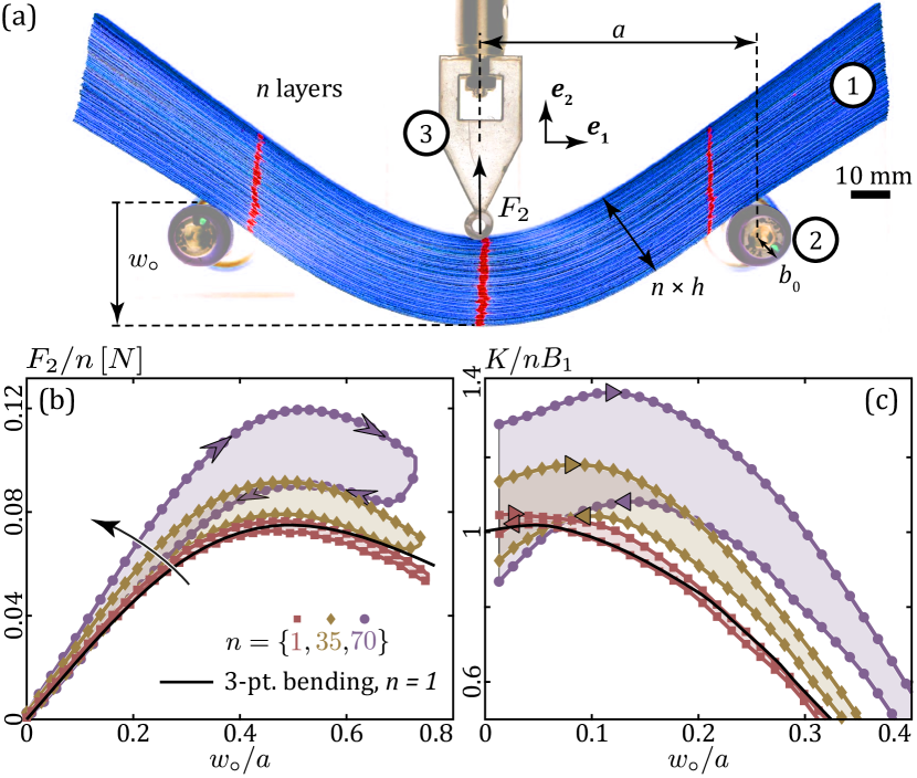
In our experiments, we quantify the resistance to bending of a book-like system by performing mechanical tests of a stack of plates in a 3-point bending configuration (see photographs of the apparatus in Fig. 1a and [18, S.I]). This canonical testing geometry is well-established for the characterization of the mechanics of beams, including in the large deflection regime [20, 21]. We seek to quantify the effect of frictional dissipation between the plates on the mechanical response of the system. Our stack comprises plates made of PolyEthylene Terephthalate (PET, Partwell group), each with dimensions . The number of plates is varied in the range . Both faces of the plates are roughened using sandpaper (K, Emil-Lux Gmbh) to avoid interlayer adhesion and ensure reproducible dry-friction interactions [22]. The 3-point bending configuration is established by two fixed lower supports, separated by , and an indenter located at mid-span. The fixed supports are set as rollers, comprising two steel cylinders (radius ) coated with a film of VinylPolySiloxane (thickness ) to prevent sliding, and mounted on air-bearings (IBS Precision Engineering, pressure ) to offer nearly frictionless rotation. The reaction force at the indenter, , is measured by a universal testing machine (Instron 5943). The imposed-displacement indentation is performed cyclically, at constant speed (), such that the mid-span deflection is varied in the range . The geometry and loading conditions ensure that each plate remains in the elastic regime. Our experimental apparatus yields highly reproducible and precise mechanical response measurements (further evidence provided in [18, S.I]).
In Fig. 1(b), we plot representative curves of the average load per plate, , for cycles with amplitude , at selected values of . For , the response agrees with the classic prediction for large-deflection 3-point bending; there is a linear regime followed by a maximal load with no hysteresis during unloading (see [18, S.II]). We find that both the maximal load per layer and the energy dissipation through friction (area of the hysteresis loop) increase with , implying that the behavior of the stack is not a superposition of independent layers. To address this nonlinear response, we introduce the incremental stiffness ; the prefactor ensures that for small deflection and without friction, where is the bending rigidity of a single plate, , is the Young modulus and is the Poisson’s ratio. In Fig. 1(c), we plot , using the same data as in Fig. 1(b), for a loading-unloading cycle. The limiting value for small deflections is 1 for , and increases with , implying that, when , friction affects even the initial response. In addition, the loading curves display an increasingly pronounced hysteresis as increases: the incremental stiffness is different between loading and unloading. The maximum stiffness, , provides a robust measure of the bending rigidity of the stack; we define one for loading, , and one for unloading, .
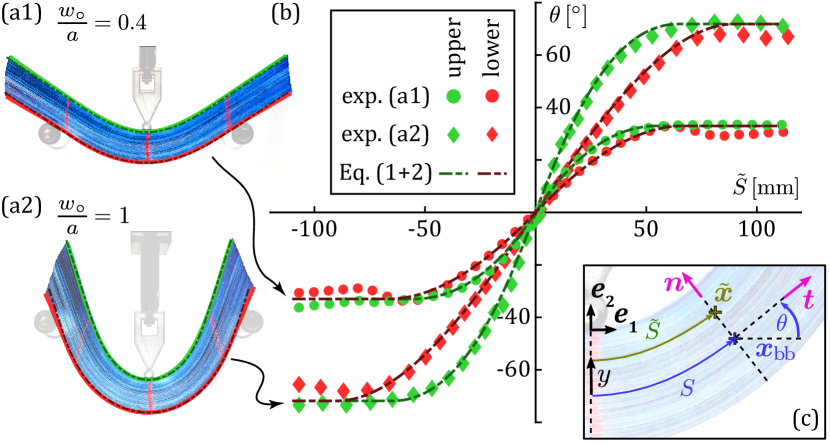
Having characterized the overall loading response of our stacks, we proceed by further quantifying the kinematics of a bent stack. By way of example, we select a thick stack with and focus on two representative configurations at moderate and large deflections, and , see Fig. 2(a1,a2). The schematic diagram in Fig. 2(c) defines the quantities used in the geometric analysis: is the tangent orientation, and is the arc length measured along a specific plate. In Fig. 2(b), we plot the profiles for the uppermost and lowermost plates, for the two selected indentation levels. The profiles of the uppermost and lowermost plates are different, especially at larger indentations: the former is more localized than the latter. An appropriate model for the stack must account for these through-thickness variations.
We visualize the extent of shear in our book-like system by physically painting three red lines on the lateral face of the stack (see Fig. 2a1,a2), perpendicularly to its centerline in the undeformed configuration. During the deformation ensued by the 3-point bending test, we find that the two outer lines lose perpendicularity to the centerline, indicating that there is significant shear. The non-penetration of the contacting plates is at the source of this shear build-up, which is known to arise in parallel bundles of inextensible curves [23]; strong geometric constraints couple the layers in the stack. A well-known model for thick and shearable beams is that of Timoshenko [24, 25]; however, it is inapplicable here as it assumes that the shear stress has an elastic origin.
To rationalize our experimental results, we build a 1D model for thick beams that accounts for internal friction at the interfaces of the layers. Similar reduction methods for bundles of slender components have recently been employed to describe helical strips [26, 27] or bundled filaments [28], albeit in different geometries than ours and without considering friction. The centerline of the stack is represented as an inextensible curve with arc length and curvature ; we reserve the symbol for arc lengths measured along the stack’s centerline, whereas pertains to the arc length along a specific plate. The transverse coordinate varies from at the lowermost plate to at the uppermost one. In the absence of delamination, the final position of a point belonging to the plate offset by from the stack’s centerline writes as
| (1) |
where is the unit normal to the centerline (Fig. 2c). Note that in our non-Lagrangian parameterization, the final position is viewed as a function of the arc length of its projection onto the centerline in the final configuration. Thus, is different from the Lagrangian arc length , and provides a measure of shear. The two arc lengths are related as due to the combined effects of curvature and plate inextensibility, as shown in [18, S.II] by differentiating Eq. (1).
From Eq. (1), the curvature of a plate is . The bending energy of the stack is found by summing the contributions from each plate, yielding , where and is the arc length where contact with the rollers takes place, (see [18, S.II]). The range of the integration to obtain has been restricted to , given both the symmetry of the solution and the fact that the overhanging parts of the slack beyond the supports remain straight and, therefore, carry no energy.
The strain energy potential defines an equivalent nonlinear beam model for the stack, with an internal moment given by the constitutive law . Following a variational approach (see [18, S.II]), one obtains the governing equilibrium (Kirchhoff) equations for planar rods,
| (2) |
where primes denote differentiation with respect to , is the indentation force, and the reaction force at the support is written as . The centerline satisfies and . The boundary conditions are and , with as the effective radius of the support.
Solving the boundary-value problem in Eq. (2) yields the centerline ; this solution ignores friction and will be referred to as the elastic backbone. The shape of the full stack can be reconstructed using Eq. (1). In Fig. 2(a), we find excellent agreement between the computed and the experimental shapes of the uppermost and lowermost plates. As part of the solution process, one also obtains the indentation force .
Next, we address the interlayer friction to rationalize the hysteresis observed in the experiments. Treating friction as a perturbation, we use the (frictionless) elastic backbone solution obtained above to estimate the power dissipated by friction. This is the integral over all the plate-plate interfaces of the sliding velocity multiplied by the tangential contact stress. From Amontons-Coulomb law of friction, the tangential contact stress is the friction coefficient times the normal stress . Reconstructing the stress in the backbone solution and carrying out a partial integration in the transverse direction, one obtains the expression of the dissipated power as [18, S.III]
| (3) |
where dots denotes differentiation with respect to time and .
The first term in Eq. (3) represents the dissipation by the point-like contact force at the supports, while the second term is the dissipation everywhere else in the stack. By symmetry, there is no sliding (hence, no dissipation) at the indentation point. The indentation force is then derived by a global balance of power as
| (4) |
Whereas and change sign between loading and unloading, does not, implying that is different during the two phases.
Before the indentation force can be computed from Eqs. (3–4), the kinematic friction coefficient must still be obtained. Friction coefficients for dry surfaces are known to be sensitive to the magnitude of the normal load [17], which, in our system, varies significantly depending on both the amount of indentation and the position along the stack [18, S.III]. Therefore, an independent measurement of may not be relevant. Instead, we proceed by extracting directly from the experimental data by leveraging the variations of the stacks stiffness as a function of . In the limit of small deflections (see [18, S.IV]), our model yields with as the bending stiffness of the backbone solution. Exploiting the linear relation between and provides the friction coefficient as (see [18, S.V] for more details on how and where obtained from the experimental data). The indentation force can now be obtained from Eqs. (2–4) to compute the loading curves over the entire indentation range. In Fig. 3a, we compare the predictions from our model (solid curves) with the experiments (data points), finding excellent agreement between the two, for different values of , with a single parameter that was fitted to the data once and for all.

In Fig. 3(b), the energy dissipated during one loading cycle is plotted as a function of the scaled maximum indentation depth. From the experimental data, is measured as the area enclosed by the loading-unloading curves. The model predictions are accurate over the entire range of parameters, from thin to thick stacks and small to large deflections; i.e., and , respectively. For small indentations, the curves collapse onto a straight line in the logarithmic plot, corresponding to the power-law applicable to small deflections (see [18, S.IV]).
In closing, we highlight that the ability of our centerline-based theory to accurately capture the mechanical behavior of a stack of frictional plates was a priori not straightforward, given the non-conservative nature of the system. We circumnavigated this challenge by treating friction perturbatively while tracking the localized dissipative regions and considering the full coupling between elasticity and nonlinear geometry. Regarding potential applications, our most significant result is that the energy dissipated per cycle can vary over orders of magnitude. The mechanism that we have uncovered for stacks of frictional plates could be harnessed to design new classes of low-cost and efficient damping devices. As geometry, elasticity, and friction are the sole ingredients, the proposed dissipative mechanism should be applicable across a wide range of length scales. Whereas we focused on a quasi-static setting, dynamic and impact conditions should also be included in future research efforts, which we hope the current study will instigate.
Acknowledgements.
References
- Vinson [2001] J. R. Vinson, Applied Mechanics Reviews 54, 201 (2001).
- Jackson et al. [1988] A. Jackson, J. F. Vincent, and R. Turner, Proceedings of the Royal society of London. Series B. Biological sciences 234, 415 (1988).
- Tang et al. [2003] Z. Tang, N. A. Kotov, S. Magonov, and B. Ozturk, Nature materials 2, 413 (2003).
- Yin et al. [2019] Z. Yin, F. Hannard, and F. Barthelat, Science 364, 1260 (2019).
- Wang et al. [2019] G. Wang, Z. Dai, J. Xiao, S. Feng, C. Weng, L. Liu, Z. Xu, R. Huang, and Z. Zhang, Physical Review Letters 123, 116101 (2019).
- Bruet et al. [2008] B. J. Bruet, J. Song, M. C. Boyce, and C. Ortiz, Nature materials 7, 748 (2008).
- Ali et al. [2019] H. Ali, H. Ebrahimi, and R. Ghosh, Scientific reports 9, 1 (2019).
- Umali et al. [2017] J. A. Umali, L. L. Wilson, and S. Pellegrino, 4th AIAA Spacecraft Structures Conference (2017), 10.2514/6.2017-1115.
- Ran et al. [1994] J. Q. Ran, E. K. S. Passaris, and P. Mottahed, Rock Mechanics and Rock Engineering 27, 235 (1994).
- Bograd et al. [2011] S. Bograd, P. Reuss, A. Schmidt, L. Gaul, and M. Mayer, Mechanical Systems and Signal Processing 25, 2801 (2011).
- Griffin [1990] J. H. Griffin, International Journal of Turbo and Jet Engines 7, 297 (1990).
- Badrakhan [1994] F. Badrakhan, Journal of Sound and Vibration 174, 91 (1994).
- Osipenko et al. [2003] M. Osipenko, Y. Nyashin, and R. Rudakov, International Journal of Solids and Structures 40, 3129 (2003).
- Hansen and Spies [1997] S. Hansen and R. Spies, Journal of Sound and Vibration 204, 183 (1997).
- Sedighi et al. [2013] H. M. Sedighi, K. H. Shirazi, and K. Naderan-Tahan, Journal of Vibration and Acoustics 135, 061006 (2013).
- Asker et al. [2018] H. K. Asker, J. A. Rongong, and C. E. Lord, Mechanical Systems and Signal Processing 101, 168 (2018).
- Alarcón et al. [2016] H. Alarcón, T. Salez, C. Poulard, J.-F. Bloch, E. Raphaël, K. Dalnoki-Veress, and F. Restagno, Physical Review Letters 116 (2016), 10.1103/PhysRevLett.116.015502.
- Sup [2020] (2020), see Supplemental Material below for details on the model’s derivations, experiments reproducibility and measure of .
- Audoly and Pomeau [2010] B. Audoly and Y. Pomeau, Elasticity and Geometry (Oxford Univ. Press, 2010).
- Ohtsuki [1986] A. Ohtsuki, Bulletin of JSME 29 (1986).
- Batista [2015] M. Batista, International Journal of Non-Linear Mechanics 69, 84 (2015).
- Baumberger and Caroli [2006] T. Baumberger and C. Caroli, Advances in Physics 55, 279 (2006).
- Pham [1992] B. Pham, Computer-Aided Design 24, 223 (1992).
- Timoshenko [1921] S. P. Timoshenko, The London, Edinburgh, and Dublin Philosophical Magazine and Journal of Science 41, 744 (1921).
- Li and Li [2016] D.-K. Li and X.-F. Li, Comptes Rendus Mécanique 344, 556 (2016).
- Ansell et al. [2019] H. S. Ansell, D. S. Kim, R. D. Kamien, E. Katifori, and T. Lopez-Leon, Physical Review Letters 123, 157801 (2019).
- Noselli et al. [2019] G. Noselli, M. Arroyo, and A. DeSimone, Journal of the Mechanics and Physics of Solids 123, 234 (2019).
- Atkinson et al. [2019] D. W. Atkinson, C. D. Santangelo, and G. M. Grason, New Journal of Physics 21, 062001 (2019).