Towards Intelligent Reconfigurable Wireless Physical Layer (PHY)
Abstract
Next-generation wireless networks are getting significant attention because they promise 10-factor enhancement in mobile broadband along with the potential to enable new heterogeneous services. Services include massive machine type communications desired for Industrial 4.0 along with ultra-reliable low latency services for remote healthcare and vehicular communications. In this paper, we present the design of intelligent and reconfigurable physical layer (PHY) to bring these services to reality. First, we design and implement the reconfigurable PHY via a hardware-software co-design approach on system-on-chip consisting of the ARM processor and field-programmable gate array (FPGA). The reconfigurable PHY is then made intelligent by augmenting it with online machine learning (OML) based decision-making algorithm. Such PHY can learn the environment (for example, wireless channel) and dynamically adapt the transceivers’ configuration (i.e., modulation scheme, word-length) and select the wireless channel on-the-fly. Since the environment is unknown and changes with time, we make the OML architecture reconfigurable to enable dynamic switch between various OML algorithms on-the-fly. We have demonstrated the functional correctness of the proposed architecture for different environments and word-lengths. The detailed throughput, latency, and complexity analysis validate the feasibility and importance of the proposed intelligent and reconfigurable PHY in next-generation networks.
Index Terms:
Intelligent reconfigurable architecture, Zynq SoC, physical layer, machine learning, multi-Armed BanditI Introduction
Upcoming 5G and 6G networks are expected to enable smarter agriculture, remote health-care access, Industry 4.0, and intelligent transportation. To bring this to reality, they are envisioned to support enhanced mobile broadband (high throughput), mission-critical services (reliability and ultra-low latency), and a massive Internet of Things (lower data rates, ultra-dense deployment, and extended battery life) [1, 2, 3]. Recent 5G 3GPP specifications follow a revolutionary path of spectrum sharing in licensed and unlicensed spectrum with a significant overhaul of the physical (PHY) layer. In this direction, 5G PHY supports features such as tunable sub-carrier spacing, bandwidth and modulation, robust synchronization scheme, and improved channel coding for reliable communication [1, 2, 3, 4]. The design of updated PHY is important for the upcoming 5G but not sufficient to enable all the above services. It lacks flexibility and significantly depends on upper layers for various decision-making tasks. Real 5G and subsequent 6G i.e. single network enabling heterogeneous services with diverse requirements, cannot be realized without intelligent and reconfigurable PHY [5]. Hence, new PHY algorithms, efficient mapping to reconfigurable architectures, and advances in artificial intelligence to embed intelligence need to be explored.
The PHY involves various baseband signal processing tasks such as channel coding, data modulation, resource allocation, layer mapping, precoding, and waveform modulation [5]. Some of these blocks demand reconfigurable architecture in 5G. For instance, data modulation with different modulation schemes, transmission bandwidth, sub-carrier spacing, interleaving, and precoding parameters can be changed dynamically [1, 2, 3, 5]. Similarly, the orthogonal frequency division multiplexing (OFDM) waveform, which has been successfully deployed in 4G, is selected as a 5G waveform. However, to improve the out-of-band attenuation of OFDM in certain deployment, researchers are exploring various windowing/filtering along with the tunable guard interval [2, 6, 7, 8, 9, 10]. Thus, depending on the environment, an on-the-fly switch between PHY parameters is desired. In this direction, making the PHY reconfigurable is important from next-generation network perspective [11, 12, 13, 14, 15].
Reconfigurable PHY can adapt to the changing unknown environment but needs intelligence to learn the environment and dynamically choose the reconfiguration parameters. For example, depending on the channel conditions and throughput desired by underlining services, appropriate PHY parameters such as channel coding rate, modulation scheme, and transmission bandwidth needs to be selected. Furthermore, depending on the selected carrier frequency and given spectrum occupancy, waveform (OFDM, Windowed-OFDM, and Filtered-OFDM) needs to be configured appropriately to meet the desired throughput and interference constraints. With the introduction of a wide range of heterogeneous services, 3GPP has proposed various base-station splits that do not guarantee tight integration of the media access control (MAC) with PHY. Thus PHY with embedded intelligence needs to be explored and is the focus of the proposed work.
In this paper, we design and realize end-to-end intelligent and reconfigurable PHY on Zynq system-on-chip (ZSoC) consisting of an ARM processor as a processing system (PS) and field-programmable gate array (FPGA) as programmable logic (PL) [16]. The hardware-software co-design based profiling approach is used to divide the proposed architecture between PS and PL. The reconfiguration at PS can be easily achieved via software up-gradation, while the dynamic partial reconfiguration (DPR) feature of FPGA is needed for reconfigurability at PL. In the end, we explore a multi-armed bandit (MAB) based online machine learning (OML) algorithms to embed intelligence at the PHY layer [17, 18, 19, 20, 21, 22]. The main contributions of the paper are summarized as below:
-
1.
We design and implement wireless transceiver on Zynq SoC and demonstrate the reconfigurable architecture via DPR. For illustrations, we demonstrate the on-the-fly configuration of the modulation scheme and validate its functionality in various wireless channel conditions along with the advantages over the Velcro approach. In the Velcro approach, multiple blocks are multiplexed in parallel, and all blocks are active even though the output of only one block is used.
-
2.
We design and map the MAB based upper confidence bound (UCB) algorithm and its extensions such as UCB_V and UCB_T on ZSoC. The MAB algorithms are based on exploration and exploitation trade-off, and they help o identify optimum parameters (wireless channel, modulation, etc.) without any prior knowledge of the environment.
-
3.
We explore DPR to make the MAB architecture reconfigurable in terms of the number of arms and algorithm type. For instance, depending on the environment, the proposed reconfigurable architecture allows the dynamic switch between MAB algorithms. This is important since a single MAB algorithm may not be suitable in all environments as well as for a given performance and complexity trade-off.
-
4.
We integrate the MAB architecture with a wireless transceiver and demonstrate intelligent and reconfigurable PHY functionality via the practical wireless application. We show the intelligent on-the-fly selection of modulation scheme and wireless channel to improve throughput.
-
5.
We demonstrate the gain in throughput and bit-error-rate (BER) along with resource utilization and power consumption over conventional approaches. We also discuss the effect of word-length (WL) on the performance and resource utilization of the proposed architecture.
The rest of the paper is organized as follows. The review of related works is discussed in Section II. Section III describes the design details of the intelligent and reconfigurable PHY. Section IV explains the proposed reconfigurable architecture of the MAB algorithm followed by PHY architecture in Section V. The complete architecture of reconfigurable and intelligent PHY, along with the illustrative demonstration, is presented in Section VI. Performance analysis and complexity comparison results are discussed in Section VII. Section VIII concludes the paper.

II Related Work
This section discusses various state-of-the-art works dealing with the design, implementation, and performance analysis of reconfigurable and intelligent PHY.
Wireless PHY has evolved significantly over the years, and there have been significant changes at the algorithm and architecture level. The multi-carrier waveform modulation approaches, such as OFDM and its variants, have been widely deployed in 4G and WiFi networks. Various works dealing with filtering and windowing approaches to improve OFDM performance are discussed in [10, 9, 8]. The filter-bank multi-carrier with offset quadrature amplitude modulation (FBMC/OQAM) offers better out-of-band attenuation than OFDM but suffers from high complexity. In [23], low complexity pipelined architecture for FBMC/OQAM is proposed by optimizing in-built filter architecture resulting in 40-50% reduction in complexity. Please refer to [24] for more details of the various hardware implementation of waveform modulation techniques being considered in 5G.
With the introduction of a wide variety of services and applications, there is a surge of interest in the design of reconfigurable PHY. In the last decade, reconfigurable PHY-based software-defined radios (SDR) were envisioned, which can reconfigure itself on-the-fly, thereby offering flexible and upgrade-able architectures [25, 26, 8]. For the realization of PHY, the first step is to validate its functionality in the real-radio environment, and Universal Software Radio Peripheral (USRP) based testbed is widely used for such performance analysis [27, 28, 29, 30]. These testbeds allow the software-based implementation of the baseband algorithms and RF front-end to validate the performance in a real radio environment. However, it does not consider the effect of quantization due to finite word-length and implementation complexity in terms of area, delay, and power. Thus, various platforms such as ARM processor, FPGA, ASIC, and ZSoC have been explored to implement end-to-end PHY.
The work in [26] demonstrates the FPGA implementation of PHY via the HDL Coder toolbox of the MATLAB/Simulink and its validation in the real-radio environment. In [11], low complexity and reconfigurable architecture for universal-filtered multicarrier (UFMC) waveform is proposed along with its implementation on FPGA. Detailed performance analysis demonstrates the advantage of FPGA implementation over software (i.e., processor) based implementation. In [31, 12], PHY is integrated with reconfigurable spectrum sensing unit to identify vacant spectrum resources in real-time. Such radios are referred to as cognitive radio (CR). Similar work has also been carried out in [32] via low complexity spectrum sensing algorithms. These works are based on mapping algorithms to low complexity efficient architecture on the homogeneous platform but offer limited flexibility and reconfigurability.
Recently, a hardware-software co-design approach to realize IEEE 802.11a PHY on heterogeneous ZSoC via HDL Coder is presented [13]. Various configurations are explored to identify the appropriate boundary for the division of PHY between PS and PL. In [10, 9], we developed the end-to-end PHY for the deployment of the air-to-ground communication in -band spectrum and realized it on the ZSoC along with RF front-end. The various filtering and windowing approaches are discussed to improve the transmission bandwidth without compromising the out-of-band interference to -band legacy users. Also, the effectiveness of such approach is demonstrated via in-depth performance analysis for various parameters such as out-of-band attenuation, interference, bit-error-rate, word-length, and complexity in the presence of various RF impairments and air-to-ground specific wireless channels.
As discussed in Section I, efficient design and implementation of PHY are desired, but reconfigurable and intelligent PHY is critical to bring various envisioned services in next-generation networks to reality. Very few works have been done in this direction. In [15], reconfigurable PHY, which allows the dynamic switch between two different communication standards via DPR, is presented, and switching decision is carried out by a vertical handover algorithm based on a scoring system. In [33], CR with PHY in FPGA and upper layers in the ARM processor is presented, and the digital front-end of the PHY is made reconfigurable via DPR. [33] proposed the CR architecture, which does not need separate filtering architectures for channelization and spectrum sensing. The DPR is used to replace a low pass filter for channelizer with the polyphase filter bank for spectrum sensing and vice-versa. Similarly, in [14], DPR has been explored to design end-to-end PHY. It can be observed that DPR and hardware-software co-design offer a state-of-the-art approach to make PHY reconfigurable. However, reconfigurable PHY needs intelligence and decision making from the upper layers to decide when and what to reconfigure. In 5G, with the separation of radio unit and distribution unit, PHY and upper layers may not be housed in the same unit, and hence, intelligence at the PHY level is desired. Furthermore, with the recent progress in AI/ML algorithms, hardware-based acceleration of the decision making algorithms of upper layers must meet the area, power, and latency constraints [34, 35].
In this paper, we explore MAB algorithms for the decision making tasks [17, 18, 19, 20, 21, 22]. MAB algorithms are designed to identify the best arm among several arms in an unknown environment. They guarantee optimal balance between exploration (select all arms a sufficient number of times) and exploitation (select best arm as many times as possible). Popular MAB algorithms include the upper confidence bound (UCB) algorithm and its extensions (UCB_V and UCB_T), Kullback-Leibler (KL) divergence based UCB algorithm (KLUCB), and Thompson sampling (TS) [17, 18, 19, 20, 21, 22]. To the best of our knowledge, none of these algorithms have ever been realized on the SoC. Furthermore, various works have shown that a single MAB algorithm may not guarantee optimal performance under various constraints (performance, area, delay, and power) [17, 18, 19, 20, 21, 22]. Since the power consumption increases linearly with the number of arms, Velcro approach of parallel implementation of all algorithms for all arms is extremely inefficient. Hence, reconfigurable architecture that allows on-the-fly switching between algorithms and the number of arms is desired, and it is one of the important contributions of the proposed work.
III Intelligent and Reconfigurable PHY
The block diagram of the proposed intelligent and reconfigurable PHY is shown in Fig. 1. The transport block (TB), i.e., the data to be transmitted, is received from upper layers, and it is assumed to be available in memory. The PL, i.e., ARM processor, reads and forwards the TB to the transmitter PHY after receiving the transmit control signal from the upper layer. The TB is processed by channel encoder, data modulator followed by waveform modulation. In the end, the preamble is appended, and the baseband signal is transmitted over one of the selected channels. The received signal on one of the selected channels is processed to detect preamble and identify the OFDM symbol boundary at the receiver. This is followed by channel estimation based on the received and transmitted pilots. Other than channel equalization, the rest of the baseband processing at the receiver is the same as that of the transmitter except that processing is carried out in the reversed direction, and each block performs the inverse operation of the corresponding transmitter block. The performance analysis block compares the transmitted and received TB and calculates the bit-error-rate, latency, and throughput. The DPR and dynamic parameter configuration (DPC) block allow the on-the-fly configuration of various transceivers’ blocks. The DPR and DPC blocks are configured by the device configuration (DevC) unit of the PS. The MAB block realizes the learning algorithm and provides input to the DevC block.
The complete PHY is realized on the ZSoC, and the detailed tutorial explaining the step-by-step process is described in the supplementary [36]. All the blocks in PL are realized using Verilog with wishbone protocol for inter-block communication, while all blocks in PS are realized in C++. PL and PS’s communication are established via multiple Advanced eXtensible Interface (AXI) Stream and Lite interfaces. In the next Sections, we discuss the design details of MAB algorithms followed by building blocks of the wireless PHY.
IV Reconfigurable Architecture for MAB Algorithms
MAB algorithms are designed to explore available arms, , and exploit the optimum arm in a horizon of size, . The distribution of arms is assumed to be unknown. In our setup, the arms correspond to wireless channels. Since next-generation networks are expected to operate in a licensed, shared, and unlicensed spectrum, complete knowledge of channel availability and fading may not be available and may change over time. Thus, base stations and mobile terminals must-have capability to identify the optimum channel for a given environment for which MAB algorithms offer attractive solution [17, 18, 19, 20, 21, 22]. In this paper, we focus on efficient mapping of the MAB algorithm on reconfigurable architecture. For illustration, we discuss the UCB algorithm and its extensions. However, the proposed architecture can be extended to other MAB algorithms as long as they are synthesizable on the SoC.
For wireless communication applications, the time is slotted with a horizon size of and the horizon is equivalent to the channel coherence time during which its characteristics or distribution remains unchanged. In each time slot, the algorithm can select only one wireless channel denoted by . The transmitter PHY is then configured to transmit over the selected channel. At the end of the time slot, the algorithm receives the reward, , for the selected channel (i.e., only one feedback in each time slot) from the receiver. Here, the reward is the ratio of received pilot power to the transmitted pilot power. Other types of rewards, depending on channel occupancy and noise variance, can be easily incorporated.
In the first time slots of the UCB algorithm, each channel is selected once. After that, in each subsequent time slots, quality factor (QF), is calculated for each channel. The value of is given by [17],
| (1) |
where
| (2) |
| (3) |
| (4) |
where is the power of the received pilot, and is the power of the transmitted pilot in the slot. is an indicator function and it is equal to 1 (or 0) if the condition, is TRUE (or FALSE). The parameter, , is an exploration factor that can take any value between 0.5 and 2. Based on calculated QFs in each time slot, the channel with the highest QF is selected, and it is denoted by .
| (5) |
Similarly, QF is calculated for UCB_V and UCB_T algorithms. We denote and be the QFs in UCB_V and UCB_T respectively. Then,
| (6) |
| (7) |
where
| (8) |
| (9) |
From a performance and complexity perspective, UCB and UCB_T select the arm having the highest mean reward (i.e., throughput), and UCB_T offers lower regret (i.e., higher reward and throughput) than UCB [17, 18]. The UCB_V algorithm selects the arm based on mean as well as variance. Among the three, UCB_T is the most complex (area, delay, and power), followed by UCB_V. The KLUCB offers the best theoretical performance, but it is significantly complex due to the underlining optimization problem [17, 20]. The TS algorithm is difficult to realize on hardware due to an in-built function for which architecture does not exist [19]. In this paper, we focus on UCB, UCB_V, and UCB_T algorithms.111We have also realized KLUCB on ZSoC, but corresponding architectural details are skipped due to space constraints. To the best of our knowledge, this work is the first attempt towards the realization and performance analysis of the MAB algorithms on the hardware. Next, we discuss the mapping of the UCB algorithms to efficient architecture for realization on the SoC. In one-time slot of the MAB algorithm, three operations are performed sequentially: 1) Initialization and parameter update (IPU) to update parameters X (Eq. 2), T (Eq. 4), Y (Eq. 9) and , 2) QF calculation for each channel based on the updated parameters (Eq 1, Eq 6 and Eq 7), and 3) Channel selection using updated QFs (Eq. 5).
IV-A Initialization and Parameter Update (IPU) Block
The IPU block operates either in the initialization (INIT) mode or learning (LEARN) mode. The INIT mode is of duration slots in which all parameters are set to zero in the first slot and updated in the subsequent slots as per Eq. 2, Eq. 4, and Eq. 9. In the INIT mode, each channel is selected once via pseudo-random sequence generator of length , and hence, QF calculation and channel arm selector blocks are not enabled. After the first slots, the algorithm enters into the LEARN mode, where the IPU block updates the parameters based on the information received via feedback signal. The IPU block architecture, shown in Fig. 2, consists of adders, delays, decoders, and a pseudo-random sequence generator.
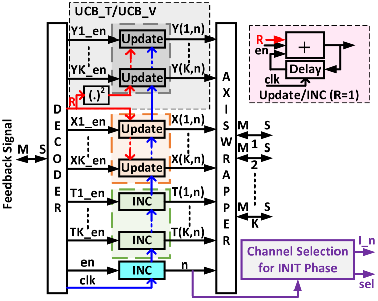
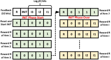
The feedback signal is the input to the IPU block, and it is received from the wireless PHY. It gives the information about the status of the channel selected in the previous time slot, , mode (INIT or LEARN), and the corresponding reward, . For channels, we need bits, and since AXI registers are of 32 bits, the rest of bits represent the reward (Eq. 3) which can take any value between 0 and 1. Higher the reward, the better the quality of the channel. The feedback signal format with illustrative INIT mode operation for is shown in Fig. 3. For easier understanding, the channels are shown to be selected in the deterministic order. However, the channels are selected in a pseudo-random manner using a pseudo-random sequence generator such that each channel is selected once in the INIT mode.
The feedback signal is decoded, and corresponding enable signals are generated, as shown in Fig. 2. For instance, en is generated at the beginning of every slot. Based on the channel selected in the previous time slot, appropriate , and are generated. For example, if the second channel is selected, then , and are HIGH and rest are LOW. Also, is the reward received in the previous slot, which is added to in the update block, as shown in Fig. 2. Similarly, the squared value of is used for updating . Since and are incremented by 1, INC block is used which is same as update block with . Note that the channel selection block is enabled only when .
IV-B Quality Factor Calculation
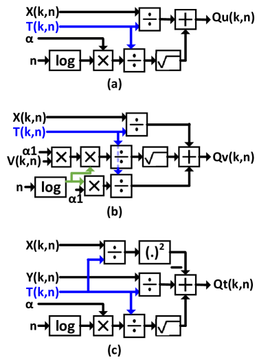
The next step after IPU is to calculate the QF for every channel using the parameters updated by IPU. The architectures QF calculation of single channels corresponding to UCB, UCB_V, and UCB_T algorithms are shown in Fig. 4. The architectures are based on Eq. 1, Eq. 6 and Eq. 7. Note that we have omitted AXI handshake signals to maintain the clarity of the architecture. Also, QF of all channels is done in parallel in the PL, while PS implementation results in sequential implementation leading to high latency, as discussed later in Section VII.
All inputs in Fig. 4 are received via the AXI4-stream interface with the IPU block. Similarly, there is a single AXI4-stream interface at the output, which is interfaced with the channel selection block. The IPU and QF calculation block can be combined into one block. However, since the feedback signal is received from PS via the AXI4-Lite interface, resultant latency is significantly high due to four handshakes compared to a single handshake in the current architecture. All the architectures in Fig. 4 are realized using floating as well as fixed-point arithmetic. We have explored various combinations of WL, and corresponding results are discussed later in Section VII.
IV-C Channel Selection
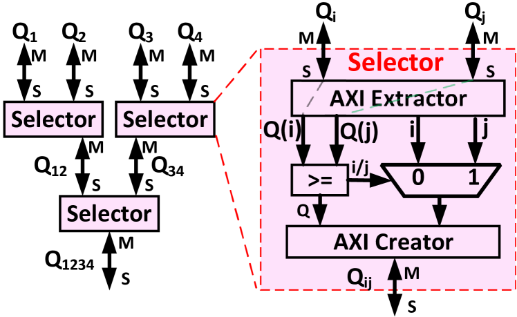
In each slot, the channel with maximum QF value is selected by comparing the QF values received from the QF calculator block, and the corresponding architecture for is shown in Eq. 5. The output of the selection block is channel index , which is used by wireless PHY for the data transmission in the rest of the time slot.
V Wireless PHY Architecture
This section briefly discusses the design details of various transmitter and receiver PHY blocks on PL via Verilog-based IPs. We begin with the wishbone protocol details, which is used for communication between multiple blocks inside PL.
V-A Wishbone Protocol
Wishbone is an industry-standard communication protocol enabling a common interface for all the system blocks irrespective of their internal functionality. Similar to other interfaces such as AXI, the wishbone protocol allows communication between master and slave blocks. For a given interface, one block is master, and another block is a slave. The master must initiate all transactions (read, write, and block transfer). For example, in Fig. 1, for the interface between channel coding and data modulator blocks, the former is the master, and the latter is the slave. On the other hand, the data demodulator is master, and channel decoding is a slave for the interface between the two in the receiver. The important signals of the wishbone interface are given below [14]:
-
•
CLK_O:- This is a clock input signal generated using the clock output of the PS (i.e. ARM processor). In our architecture, the clock given to each block may not be the same and need to be updated depending on the given configuration. For example, the clock frequency of 16-QAM is twice that of QPSK.
-
•
RST_O:- This is reset input signal and it is connected to the reset signal output of the PS (i.e. ARM processor). This is used to bring the transmitter and receiver PHY to the known state after every time slot.
-
•
DAT_I (Master Input) and DAT_O (Slave output):- Both enables the data transfer from slave to master. Similarly, DAT_O (Master Output) and DAT_I (Slave input) enable the data transfer from master to slave.
-
•
ACK_I (Master input) and ACK_O (Slave output):- They form an acknowledge signal which is asserted by a slave to indicate the termination of a normal bus cycle.
-
•
STB_O (Master output) and STB_I (Slave input):- When a master is ready to transfer the data, it asserts the STB_O signal. Slave responds to the received strobe signal via acknowledgment signal.
-
•
WE_O (Master output) and WE_I (Slave input):- It is asserted during the write cycle and de-asserted during the read cycle.
-
•
CYC_O (Master output) and CYC_I (Slave input):- It indicates the valid bus cycle and remains asserted for all data transfers in a given bus cycle.
V-A1 Common Signals
V-B Transmitter PHY
As shown in Fig. 1, the transmitter PHY consists of various baseband signal processing blocks to convert the upper layer TB into OFDM samples for transmission over the channel. In the transmitter PHY, MAB, and DevC blocks decide the channel to be selected in a subsequent time slot, and based on the learned distribution of the selected channel, one of the modulation schemes (16-QAM or QPSK) is selected. Thus, input to the transmitter PHY is the modulation scheme, channel, and TB of appropriate size. For example, since 16-QAM maps four bits to one symbol and QPSK maps two bits to one symbol, the size of TB is twice for 16-QAM than that of QPSK.
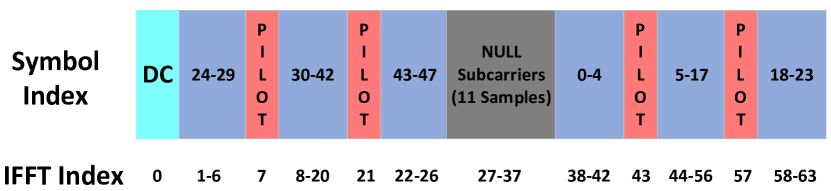
In the proposed work, the transmitter PHY is based on IEEE 802.11a specifications with 64 sub-carriers (can be extended to any other size), out of which 48 are data sub-carriers, 4 pilot sub-carriers, and 12 are null sub-carriers. The position of these sub-carries is shown in Fig. 6. For every OFDM symbol, the channel coding block generates 98 bits for QPSK or 196 bits for 16-QAM modulation schemes. These bits are converted to the symbols by the data modulation block. The proposed data modulation follows 3GPP specifications for 5G PHY and generates a complex symbol with Inphase (I) and Quadrature (Q) components. The Modulation mapping of input of single-channel (I and Q) in a signed 16-bit Q1.15 format is shown in Table I.
| Modulation Scheme | Bit | Mapped value in Hex | Signed Mapped Value |
|---|---|---|---|
| QPSK | 0 | A57E | -0.7071 |
| QPSK | 1 | 5A82 | 0.7071 |
| 16-QAM | 00 | 8692 | -0.9485 |
| 16-QAM | 01 | 287A | 0.3162 |
| 16-QAM | 10 | D786 | -0.3162 |
| 16-QAM | 11 | 796E | 0.9485 |
Similarly, pilot symbols are BPSK modulated. The phase of the pilot signal depends on its sub-carrier index and is fixed. Thus, pilot signals are pre-generated and stored in block memory of PL. As per Q1.15 format, the value of the pilot symbol is 0x7FFF and 0x8001 for +1 and -1, respectively. The modulated data and pilot symbols are mapped to appropriate sub-carriers by the resource mapping block, which acts as a serial-to-parallel converter. This is followed by a 64-point inverse Fast Fourier transform (IFFT) using Xilinx optimized IFFT block. The IFFT output is serialized to obtain 64 time-domain samples, which are then extended to 80 samples via cyclic prefix (CP) addition. Here, the last 16 samples are appended initially, which in turn reduces the impact of inter-symbol interference due to multi-path channels.
Since the transmitter and receiver PHY layers are not synchronized, receiver PHY needs to identify symbol and frame boundary, estimate and compensate the frequency offset, and perform channel estimation and equalization. In cellular communication such as 5G, synchronization and reference signals are used, while in WiFi IEEE 802.11 standard, preambles (long and short) are used. In this work, we have implemented the preamble based approach. As per IEEE 802.11 standard, a short preamble consists of 10 slots, each composed of 16 samples, while a long preamble consists of two slots of 64 samples each along with CP of 32 samples. Thus, the total preamble occupies 320 samples followed by multiple data payload, each consisting of 80 samples. In our implementation, preamble samples are fixed and are stored in block memory of PL. The preamble addition block includes the scheduler, which maps the appropriate preamble in the desired time slots.
V-C Wireless Channel
The transmit PHY selects and transmits on one of the channels, as shown in Fig. 1. Each channel is modeled as a multi-path fading channel with complex symmetric Gaussian distribution. The mean and variance of channel is denoted as and , respectively. In each time slot, the MAB algorithm selects the channel, and the sample (fading coefficient) is generated based on the distribution of the selected channel. In the proposed architecture, we have deployed the AXI-Lite interface between PS and PL to convey the selected channel’s index along with the fading coefficient to the PHY. In the PL, complex multiplication is performed between the transmit samples and fading coefficient, which is then passed to the receiver PHY.
V-D Receiver PHY
The received samples are processed in the synchronization block, followed by waveform demodulation, channel estimation, channel equalization, and data demodulation.
The first task of the receiver is to detect the preamble and used the same for synchronization tasks. For example, a short preamble is used for the start of the frame detection, and coarse frequency offset estimation, while a long preamble is used for fine frequency offset estimation. It is also used later for channel estimation.
For frame detection, an auto-correlator is designed with a window length of 32 samples, and auto-correlation is performed between a block of samples separated by 16 samples. This is also known as CP detection. The output of the auto-correlation block is given by[37, 38, 39]:
| (10) |
where * indicates complex conjugate operation and is the time index. The output of the auto-correlator is normalized as given below [37, 38]:
| (11) |
where
| (12) |
Then, vector is passed through the comparator to generate the binary signal, which goes High when the corresponding value of is above the threshold (0.75 in our case). Ideally, we get one low-to-high transition in a single frame for long preamble and one low-to-high transition for every OFDM symbol carrying data. These transitions are used to identify the start of the OFDM symbol, and hence, CP can be easily removed. Before the waveform demodulation, short preamble based auto-correlation is used to estimate coarse frequency offset, and long preamble based auto-correlation is used to estimate a fine frequency offset [37, 38]. After offset corrections, the OFDM symbol corresponding to the long preamble and data are passed through 64-point FFT. The FFT output of the preamble is used for channel estimation, which is nothing but 64 complex multiplication operations between transmitted and received preamble symbols. Data demodulation block extracts the bits from the FFT outputs via hard decoding. In the end, TB is formed, which is passed to the PS for the performance analysis.
VI Intelligent and Reconfigurable PHY on ZSoC
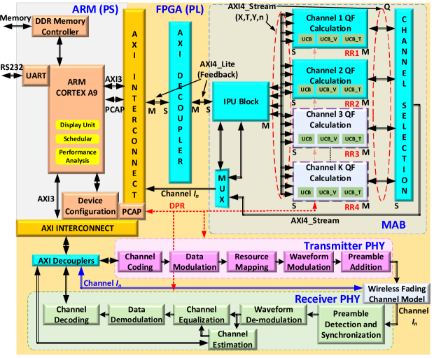
In this section, we present the complete architecture of the proposed intelligent and reconfigurable PHY realized on the ZSoC consisting of PS (Dual-core ARM processor) and PL (7-series FPGA). The architecture, shown in Fig. 7, mainly consists of MAB algorithm, transmitter, and receiver blocks in PL along with scheduler and performance analysis in PS. In [36], the detailed tutorial to build the architecture in Fig. 7 followed by enabling the DPR to make it reconfigurable along with source code is given.
As discussed in Section IV, the MAB algorithm consists of three sub-blocks, as shown in Fig. 7. At the beginning of each experiment, the PS resets the algorithm via feedback signal over the AXI-Lite interface (). In the subsequent time slots, the IPU bypasses the QF calculation and channel selection blocks to execute the INIT mode and finds the index of the selected channel, . At the beginning of each time slot, the PS generates the feedback signal containing the reward information received from the PHY. This information is used by IPU to update the MAB parameters. After the INIT mode, QF and channel selection blocks are enabled, which select the appropriate channel in the LEARN mode. We have explored the complete or partial realization of MAB in the PL. Please refer to Section VII for the performance analysis of these architectures.
For the architecture in Fig. 7 with , four reconfiguration regions (RR), i.e., the region whose functionality can be changed on-the-fly via DPR, are shown. Since each region can be configured with blank, UCB, UCB_V or UCB_T QF blocks, corresponding partial bit-streams can be stored either in on-board DDR memory or SD card. Via bare-metal application deployed on the ARM processor, the desired bit-streams are sent to the FPGA for appropriate RR configuration using the device configuration (DevC) unit of the PS. The FPGA’s DPR property achieves this, and we specifically employed ARM processor-controlled DPR via processor configuration access port (PCAP).
As discussed previously, the transmitter consists of various signal processing blocks that map the TB to OFDM symbols and transmit them over one of the channels. The transmitter architecture is reconfigurable because it dynamically adapts the modulation scheme based on the selected channel. This is also achieved via the DPR property of the FPGA configured through the ARM processor. The transmitter maps the output on the channel chosen by the MAB algorithm.
The receiver receives the transmitted OFDM samples on the chosen channel. As discussed before, the receiver estimates the channel quality based on the transmit and receive pilot powers and forwards it to the MAB algorithm via PS. The receiver decodes the received symbols and forms the TB, which is then compared with transmitted TB to obtain BER and throughput in the performance analysis unit of the PS.
Next, we demonstrate the proposed architecture’s functionality for the adaptive modulation scheme and channel selection application. For illustration, we consider two modulation schemes: 1) QPSK and, 2) 16-QAM and channels. In QPSK, one symbol comprises two bits, while in 16-QAM, one symbol contains 4 bits. Thus, when a channel is good (i.e., the noise power is less), 16-QAM is preferred to maximize the throughput. However, at high noise power, QPSK is preferred to achieve moderate throughput with good reliability. Since channels are unknown, PHY needs to learn them accurately before choosing the modulation scheme. We develop the UART based interface to display the results of each experiment.
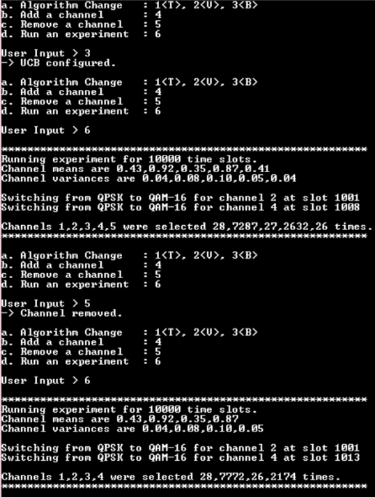
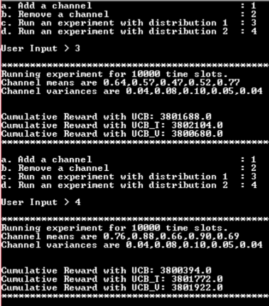
In Fig. 8, we consider channels with average throughput of and variance of . It is assumed that PHY does not have any prior knowledge of the channel. Thus, the MAB algorithm aims to identify the optimum channel via exploration-exploitation trade-off and choose an appropriate modulation scheme to maximize the throughput. Fig. 8 demonstrates the reconfigurable feature of the architecture where DPR based on-the-fly switch between UCB, UCB_V, and UCB_T algorithms is shown. Similarly, the architecture can be reconfigured for any . For each experiment, the horizon is of size 10000-time slots, and it can be seen that the algorithm selects the channel with higher average throughput more times, i.e., channel 2 is selected in 7287-time slots out of 10000-time slots. Fig. 8 also demonstrates an on-the-fly switch between the number of channels where the last channel is made unavailable, and in the new experiment, channel 2 has been selected 7772 times.
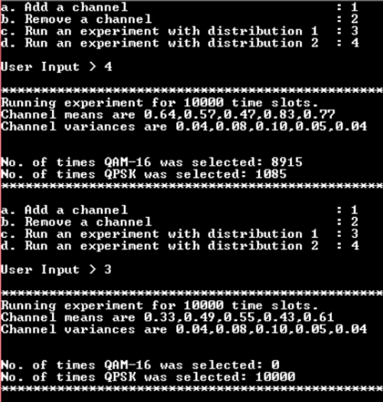
Similarly, when channel statistics are changed, the architecture intelligently chooses the appropriate configuration (modulation scheme and channel) without any prior information. Fig. 9, demonstrates that with the change in channel distribution, intelligent on-the-fly adaptation to the desired modulation scheme is accomplished without any manual intervention. For distribution 1 with good channels, 16-QAM is preferred, while for average channel conditions, QPSK is preferred due to the high BER of the 16-QAM. Please refer to Section VII for details.
Next, we demonstrate the need for reconfigurable architecture, which can switch between MAB algorithms. For illustration, the total reward at the end of the horizon size of 10000-time slots is compared. Here, the reward of the particular slot is assumed to be equal to the total number of correctly received bits in that time slot. As shown in Fig. 10, UCB_T and UCB_V algorithms offer higher rewards in the first and second cases, respectively. The proposed reconfigurable architecture does not need parallel implementation of all MAB algorithms, thereby significantly reducing complexity. In the current architecture, the user needs to select the algorithm at the beginning of the horizon since there is no existing approach to decide the appropriate MAB algorithm for a given unknown environment.
VII Performance and Complexity Analysis
In this section, we validate the functional correctness of the proposed architecture and the complexity comparison. We begin with the performance analysis of UCB architecture.
VII-A Performance Analysis of UCB algorithms
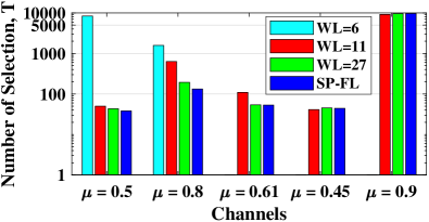
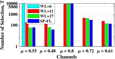
In this section, we validate the functional correctness of the proposed UCB architecture for different WL. Since the purpose of the UCB algorithms is to assist in the selection of the optimal channel via exploration-exploitation trade-off, we study the channel selected by UCB algorithm in various channel environment. We first consider = 5, = 10000 and two different channel distributions:
1) {} = {(0.5,0.01), (0.8, 0.02), (0.61, 0.08), (0.45, 0.06), (0.9, 0.07)}
2) {} = {(0.55,0.04), (0.48, 0.14), (0.8, 0.2), (0.72, 0.3), (0.61, 0.2)}.
Here, the channel is assumed to have Gaussian distribution with a mean , which corresponds to the channel’s average gain, and is the variance. In Fig. 11a and Fig. 11b, we consider three different fixed-point WLs along with a single-precision floating-point (SP-FL) architectures. It can be observed that the proposed SP-FL architecture consistently selects the fifth and third channels, which are the optimum channel (i.e., a channel with the highest gain) in distribution and , respectively. Note that all results are obtained after averaging over ten different experiments to consider the non-deterministic nature of the online machine learning algorithms. The values on the -axis are shown on the logarithmic-scale for better clarity. Thus, it can be observed that the proposed UCB architecture identifies the optimum channel quickly, i.e., it optimizes exploration-exploitation trade-off by minimizing the selection of non-optimum channels. Among the fixed-point architectures, the performance of the architectures with WL of 27 and 11 is acceptable as both select the optimum channels a higher number of times. However, for WL of 6, the UCB algorithm’s functionality is not correct as it fails to identify the optimum channel. The limited WL leads to the loss in precision of QF values, which results in multiple channels with identical QF values. In cases where more than one channel have maximum QF values, the channel selector unit selects the channel with a lower index as shown in Fig. 11.
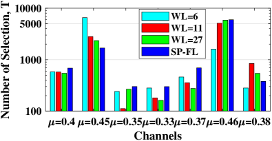
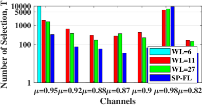
Next, we consider = 7, = 10000 and two new distributions:
1){} = {(0.4,0.01), (0.45, 0.02), (0.35, 0.08), (0.33, 0.06), (0.37, 0.07), (0.46, 0.2), (0.38, 0.1)}
2) {} = {(0.95, 0.03), (0.92,0.08), (0.88, 0.1), (0.87, 0.15), (0.9, 0.1), (0.98, 0.01), (0.82, 0.1)}.
Here, the difference between channel statistics is small, which means learning and identifying the optimal channel is challenging. As shown in Fig. 12, proposed UCB architectures select the optimum channels a higher number of times except for WL=6. In both the distributions, UCB algorithms need to explore channels 2 and 6 in and channels 1 and 6 in the sufficient number of times before exploiting the optimal channel, i.e., channel 6 in and . Similar to Fig. 11, the architecture with WL=6 fails to identify the optimal channel. For the rest of the discussion, we consider the MAB architecture with WL=11 as it offers the performance close to that of WL=27 and SP-FL architectures. Furthermore, it provides a significant reduction in resource utilization, as discussed later.
VII-B Performance Analysis of Wireless PHY
Next, UCB architecture with WL=11 is integrated with wireless PHY architecture to compare the gain in performance due to MAB algorithms. Here, we consider , , and six different channel statistics for performance evaluation in a different environment:
1) (Same as Fig. 12a)
2) (Same as Fig. 12b)
3) ={0.3,0.3,0.35,0.4,0.45,0.5,0.55}
4) ={0.35 0.4 0.45 0.5 0.55 0.6 0.65}
5) ={0.45 0.5 0.55 0.6 0.65 0.7 0.75}
6) ={0.3 0.35 0.4 0.45 0.5 0.55 0.6}
In each time slot, 48 OFDM data symbols are transmitted, equivalent to 96 and 192 bits for QPSK and 16-QAM modulation. In Fig. 13, we compare the total number of bits received in error in % for three different channel selection schemes: 1) Oracle scheme that always selects the optimal channel, 2) Random channel selection scheme, and 3) Proposed MAB based channel selection scheme. In each case, we have used a channel-based reconfigurable modulation scheme switching approach, i.e., when the channel is good, 16-QAM is used instead of QPSK. It can be observed that the proposed scheme offers significantly lower % of error bits than a random channel selection approach, thereby validating the need for MAB based decision making for channel selection. Also, the performance of the oracle and the proposed approach is almost identical, thereby validating the optimality of the UCB algorithm as well as the correctness of its architecture to identify the optimal channel quickly.

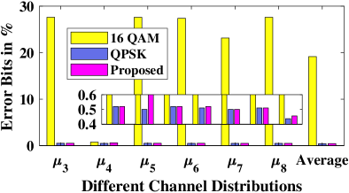
Next, we repeat the above experiment to compare three different modulation selection approaches 1) Fixed 16-QAM, 2) Fixed QPSK, and 3) Proposed channel-based modulation switching scheme. Here, the channel selection is based on the MAB based approach. As shown in Fig. 14, 16-QAM incurs a higher number of error bits due to performance degradation when the poor channel is selected. Note that around 25% bits are received in error even though MAB selects the optimal channel a large number of times. It is obvious that the error rate will increase substantially for the random channel selection approach. As expected, the lower-order modulation scheme, such as QPSK, offers the lowest number of error bits. The proposed channel based modulation switching scheme provides significantly better performance than 16-QAM and around 0.5% higher number of error bits than QPSK. This penalty is due to the time taken by the MAB algorithm to estimate channel statistics (exploration time), which allows dynamic selection of appropriate modulation schemes for a given channel. Next, we discuss the effect of intelligent channel and modulation scheme selection on average throughput.
As discussed before, PHY with 16-QAM transfers twice the number of bits than the PHY with QPSK in a given number of transmission slots. To take this into account, we compare the average throughput of the PHY for three different modulation selection approaches 1) Fixed 16-QAM, 2) Fixed QPSK, and 3) Proposed channel-based modulation switching scheme. Here, we skip the random channel selection approach due to the high error rate, as shown in Fig. 13. In Table II, we compare the total throughput in megabits per second (Mbps) and the total number of transmissions required to meet the BER of 1%. This means that the 16-QAM and proposed architecture may need to re-transmission to meet given BER constraints. Here, the feedback time or the time interval between re-transmissions is assumed to 30% of the transmission time, which means every re-transmission leads to a penalty in throughput. It can be observed that the proposed PHY offers throughput the same as that of QPSK based PHY when the channel quality is average or poor (All except the second column in Table II). On the other hand, when the channel quality is good (Second column in Table II), the proposed PHY offers significantly better throughput than other PHY. For six different channel distributions, out of which five are average or poor and one is good, proposed PHY provides better throughput and fewer re-transmission. Though the error rate of QPSK based PHY is lower than the proposed PHY in Fig. 14, the latter offers higher throughput than the former. For the environment with excellent or above-average channel conditions, the gain in throughput over QPSK based PHY will further increase.
| Average | |||||||
|---|---|---|---|---|---|---|---|
| QPSK | 50 (1) | 50 (1) | 50 (1) | 50 (1) | 50 (1) | 50 (1) | 50 (1) |
| QAM | 38.7 (5) | 76.5 (2) | 38.7 (5) | 38.8 (5) | 45.5 (4) | 38.7 (5) | 43.4 (4.3) |
| Proposed | 50 (1) | 90 (1) | 50 (1) | 50 (1) | 50 (1) | 50 (1) | 53 (1) |
The fewer number of re-transmissions makes the proposed PHY power-efficient leading to longer battery life. Also, since the error rate of 16-QAM is significantly high (above 24%), it is not suitable for a low coding rate scenario since the entire frame needs to be transmitted again due to lower code correction capability. On the other hand, the proposed approach exploits the high throughput advantages of 16-QAM and offers higher resilience to block errors, mainly due to the channel-based modulation selection approach.
VII-C Complexity Comparison
In this section, we present the detailed complexity comparison of the proposed architecture. First, we consider the proposed architecture with a reconfigurable channel based modulation scheme and fixed MAB algorithm, i.e., only the UCB algorithm is realized with a fixed . As shown in Table III, we consider the Velcro approach where QPSK and QAM modulator and demodulator blocks are realized in parallel, i.e., all four blocks are always active. In the proposed approach using DPR, the appropriate modulation scheme is dynamically configured on-the-fly. As expected, the proposed approach needs slightly lower LUTs and half the number of flip-flops (FFs) than the Velcro approach. Since the QPSK block transmits 2 bits in one resource element compare to four bits in QAM, we need a separate clock network for QPSK and QAM. Thus, the proposed approach needs fewer FFs since only one clock is active compared to two clock networks in the Velcro approach. For fixed-point implementation with WL= 27, 40%, and 80% reduction in LUTs and DSP48s (embedded multiplier and accumulator units) with almost identical BER and throughput performance as that of SP-FL architecture. With WL=11, further improvement in savings of up to 60% and 87% in resources can be achieved with negligible degradation in the BER and throughput. With the increase in the number of supported modulation schemes and the addition of other reconfigurable modules such as channel coding and waveform modulation, the proposed approach can offer further improvement in resource utilization.
|
Approach | LUTs | FFs | DSPs | |||||||
|---|---|---|---|---|---|---|---|---|---|---|---|
| Wireless PHY with QAM-16/QPSK via DPR and |
|
64828 | 41175 | 342 | |||||||
|
64796 | 21042 | 342 | ||||||||
|
|
|
|
||||||||
|
|
|
|
| No. | Architecture | Approach | No. of LUTs | No. of FFs | No. of DSP48 | Dynamic Power (W) | ||||||||
| K=3 | K=4 | K=5 | K=3 | K=4 | K=5 | K=3 | K=4 | K=5 | K=3 | K=4 | K=5 | |||
| 1 | Wireless PHY with QPSK/QAM in Velcro, fixed UCB algorithm, tunable | Velcro | 24173 | 19245 | 127 | 0.41 | ||||||||
| Proposed | 17187 | 20680 | 24173 | 15407 | 17326 | 19245 | 87 | 107 | 127 | 0.36 | 0.38 | 0.41 | ||
| -29% | -15% | -20% | -10% | -32% | -16% | -12.2% | -7.3% | |||||||
| 2 | Wireless PHY with QPSK/QAM in Velcro, fixed UCB_V algorithm, tunable | Velcro | 25263 | 20110 | 142 | 0.46 | ||||||||
| Proposed | 17841 | 21552 | 25263 | 15926 | 18018 | 20110 | 96 | 119 | 142 | 0.39 | 0.42 | 0.46 | ||
| -30% | -15% | -21% | -11% | -33% | -17% | -15.2% | -8.7% | |||||||
| 3 | Wireless PHY with QPSK/QAM in Velcro, fixed UCB_T algorithm, tunable | Velcro | 28808 | 21120 | 127 | 0.46 | ||||||||
| Proposed | 19968 | 24388 | 28808 | 16538 | 18826 | 21120 | 87 | 107 | 127 | 0.39 | 0.42 | 0.46 | ||
| -31% | -16% | -22% | -11% | -32% | -16% | -15.2% | -8.7% | |||||||
| 4 | Wireless PHY with QPSK/QAM in Velcro, reconfigurable MAB and tunable | Velcro | 64828 | 41175 | 342 | 0.75 | ||||||||
| Proposed | 19968 | 24388 | 28808 | 16538 | 18826 | 21120 | 96 | 119 | 142 | 0.55 | 0.65 | 0.75 | ||
| SP-FL | -70% | -62% | -56% | -75% | -55% | -49% | -72% | -65% | -59% | -26.7% | -13.3% | |||
| Proposed | 15326 | 18255 | 21184 | 14889 | 16768 | 18647 | 39 | 43 | 47 | 0.53 | 0.62 | 0.7 | ||
| WL=27 | -77% | -72% | -68% | -64% | -60% | -55% | -89 | -87% | -87% | -29.3% | -17.3% | -0.03% | ||
| Proposed | 11887 | 13650 | 15413 | 14091 | 15678 | 17265 | 33 | 35 | 37 | 0.35 | 0.37 | 0.39 | ||
| WL=11 | -82% | -79% | -77% | -66% | -62% | -59% | -91% | -90% | -90% | -53.3% | -50.7% | -48% | ||
| 5 | Complete reconfigurable Wireless PHY with tunable | Velcro | 64828 | 41175 | 342 | 0.75 | ||||||||
| Proposed | 19909 | 24329 | 28749 | 16460 | 18748 | 21002 | 96 | 119 | 142 | 0.55 | 0.65 | 0.75 | ||
| SP-FL | -70% | -63% | -56% | -60% | -55% | -49% | -72% | -65% | -59% | -27% | -14% | |||
| Proposed | 15267 | 18196 | 21125 | 14811 | 16690 | 18569 | 39 | 43 | 47 | 0.53 | 0.62 | 0.7 | ||
| WL=27 | -77% | -72% | -68% | -64% | -60% | -55% | -89% | -87% | -87% | -29.3% | -17.3% | -7% | ||
| Proposed | 11828 | 13591 | 15354 | 14013 | 15600 | 17187 | 33 | 35 | 37 | 0.35 | 0.37 | 0.39 | ||
| WL=11 | -82% | -79% | -77% | -66% | -62% | -59% | -91% | -90% | -90% | -53.3% | -50.7% | -48% | ||
| 6 | Reconfigurable Wireless PHY on PS | ARM | 6026 | 8533 | 27 | 0.24 | ||||||||
Next, we extend the architecture with reconfigurability at the MAB algorithm (i.e., architecture which can dynamically switch between UCB, UCB_T, and UCB_V algorithms) and (i.e., number of channels can be tuned to any values less than or equal to . In Table IV, we consider six different architectures which are discussed below:
-
1.
First architecture implements the modulation scheme via the Velcro approach, supports only the UCB algorithm and offers the DPR at the channel level, i.e., reconfigurable .
-
2.
Second architecture is similar to the first architecture except that the UCB algorithm is replaced with the UCB_V algorithm.
-
3.
Third architecture is similar to the first architecture except that the UCB algorithm is replaced with the UCB_T algorithm.
-
4.
Forth architecture implements the modulation scheme via the Velcro approach with reconfigurable MAB and , i.e., architecture can dynamically switch between UCB, UCB_V and UCB_T algorithms in addition to any .
-
5.
Fifth architecture is entirely reconfigurable and can dynamically select the modulation scheme, MAB algorithm, as well as .
-
6.
Six architecture consists of PHY on PL and MAB algorithm on PS.
In the first row of Table IV, we compare the first architecture realized using the Velcro approach and proposed approach via DPR. It can be observed that the resource utilization of the proposed approach depends on the active number of channels, compared to the Velcro approach, which corresponds to architecture with , i.e., all blocks are active all the time compared to dynamic activation and deactivation of channels in the proposed approach. In the next two rows, we compare the architectures by replacing UCB with UCB_V and UCB_T algorithms. Since QF calculation in UCB_T (Eq. 7) and UCB_V (Eq. 6) are computationally complex than UCB algorithms (Eq. 1), second and third architectures have higher resource utilization than first architecture. In all the three architectures, proposed architectures offer 7-15% savings in dynamic power consumption of the reconfigurable region over the Velcro approach for .
In the fourth architecture, reconfigurability is added at the MAB level in addition to . It can be observed that the proposed approach needs 56-70% lower LUTs, 55-65% lower FFs, and 59-72% fewer DSP48 units. Also, the proposed architecture offers power savings up to 53% in the reconfigurable region. We have also realized the fixed-point configuration of the proposed architecture for different WL. As discussed above, WL of 27 offers the BER and throughput performance similar to that of SP-FL architecture, while WL of 11 is the minimum WL, after which the BER and throughput performance degrade significantly. Thus, the selection of appropriate WL is essential to achieve the right balance between performance and complexity.
In the fifth architecture, we have included the reconfigurability at the modulation block as well, and it can be observed a slight improvement in resource utilization similar to Table III. With the increase in the number of modulation schemes, the proposed architecture will further offer savings in resources than the Velcro approach. In the sixth architecture, we have explored the ARM processor along with co-processor NEON. As expected, it provides the lowest resource utilization and power consumption. However, overall latency is significantly high due to sequential implementation in PS, which affects the throughput.
In Table V, we compare the latency of the fifth architecture for three configurations: 1) MAB algorithm in PL, 2) MAB algorithm in the ARM processor of PS, 3) MAB algorithm in ARM+NEON processor of PS. The PHY is intentionally realized in PL due to the practical constraints of interfacing the output of the transmit PHY with antenna via digital and analog front-end. Such an interface is available only on PL due to a large number of interface pins. The latency corresponds to the transmission of 10000 OFDM frames, each consisting of 320 bits of user data (4 OFDM symbols). It can be observed that the PL implementation of MAB offers the lowest latency, and performance improves as increases. This is due to the parallel execution of the QF function in PL compared to sequential PS execution. From a numerical perspective, OFDM symbol time in the proposed architecture is 17.5s. In 5G with sub-carrier spacing of 15 kHz and 30 kHz, the desired OFDM symbol time is 71.4s and 35.7s, respectively. Thus, the proposed architecture on ZSoC meets the 5G symbol time requirement. On the other hand, symbol time in the case of ARM and ARM+NEON platforms depends on the value of . For a reasonable value of , it is incredibly challenging to meet the 5G latency requirement. Thus, in real networks with , the proposed architecture can significantly improve execution time, thereby supporting high throughput and low latency applications.
| Algorithm | Approach | ZSoC (in ms) |
|
|
||||||||||
|---|---|---|---|---|---|---|---|---|---|---|---|---|---|---|
| K=2 | K=3 | K=4 | K=5 | K=2 | K=3 | K=4 | K=5 | |||||||
| Architecture 5 | SP-FL | 700 | 719 | 729 | 737 | 747 | 713 | 720 | 726 | 733 | ||||
| WL=27 | 700 | |||||||||||||
| WL=11 | 700 | |||||||||||||
VIII Conclusions and Future Directions
In this paper, we present the novel design and implementation of an intelligent and reconfigurable physical layer (PHY) for next-generation wireless transceivers. The proposed PHY is integrated with a multi-armed bandit (MAB) based learning algorithm to learn and identify the optimum channel in any given environment. To the best of our knowledge, the proposed work is the first-ever implementation of the MAB algorithm on SoC. The MAB algorithm offers intelligence to dynamic partial reconfiguration (DPR) based reconfigurable PHY, and detailed performance analysis shows that the proposed architecture offers 3 Mbps higher average throughput, lower resource utilization (overall savings of 50-80% in LUTs, 49-60% in FFs, and 60-90% in DSP units), and 14-50% lower power consumption compared to conventional PHY. The proposed demonstration of the feasibility of intelligent and reconfigurable PHY opens up a wide range of research directions involving the integration of PHY and learning algorithms. In the future, we will explore various other learning algorithms, along with their synthesizable low complexity architectures. In addition, we aim to develop an intelligent and reconfigurable prototype for 3GPP 5G PHY along with performance analysis in the real-radio environment and feasibility for real-world applications.
Acknowledgment
We would like to thank the authors of the paper [14] for source codes used in the implementation of wireless PHY.
References
- [1] S. Parkvall, E. Dahlman, A. Furuskár, and M. Frenne, “NR: The New 5G Radio Access Technology,” IEEE Communication Standards Magazine, vol. 1, no. 4, pp. 24–30, 2017.
- [2] A. Zaidi, R. Baldemair, V. Cases, N. He, K. Werner, and A. Cedergren, “ OFDM Numerology Design for 5G New Radio to Support IoT, eMBB, and MBSFN,” IEEE Communications Standards Magazine, vol. 2, no. 2, pp. 78–83, 2018.
- [3] J. Jeon, “NR Wide Bandwidth Operations,” IEEE Communication Magazine, vol. 56, no. 3, pp. 42–46, 2018.
- [4] X. Hong, J. Wang, C.-X. Wang, and J. Shi, “Cognitive radio in 5g: A perspective on energy-spectral efficiency trade-off,” IEEE Communication Magazine, vol. 52, no. 7, 2014.
- [5] S.-Y. Lien, S.-L. Shieh, Y. Huang, B. Su, Y.-L. Hsu, and H.-Y. Wei, “5G New Radio: Waveform, Frame Structure, Multiple Access, and Initial Access,” IEEE Communication Magazine, vol. 55, no. 6, pp. 64–71, 2017.
- [6] Y. L. et al., “Waveform Design for 5G Networks: Analysis and Comparison,” IEEE Access, vol. 5, no. 3, pp. 19 282–19 292, 2017.
- [7] X. Zhang, M. Jia, L. Chen, J. Ma, and J. Qiu, “Filtered-ofdm - enabler for flexible waveform in the 5th generation cellular networks,” 2015, pp. 1–6.
- [8] A. Kumar, M. Magarini, and S. Olivieri, “Rapid prototyping and fpga-in-the-loop verification of a dfrft-based ofdm system,” 2017, pp. 1–6.
- [9] S. Garg, N. Agrawal, S. J. Darak, and P. Sikka, “Spectral coexistence of candidate waveforms and dme in air-to-ground communications: Analysis via hardware software co-design on zynq soc,” in 2017 IEEE/AIAA 36th Digital Avionics Systems Conference (DASC), 2017, pp. 1–6.
- [10] N. Agrawal, S. J. Darak, and F. Bader, “Spectral Coexistence of LDACS and DME: Analysis via Hardware Software Co-Design in Presence of Real Channels and RF Impairments,” IEEE Transactions on Vehicular Technology, pp. 1–13, 2020.
- [11] V. Kumar, M. Mukherjee, and J. Lloret, “Reconfigurable Architecture of UFMC Transmitter for 5G and Its FPGA Prototype,” IEEE Systems Journal, vol. 14, no. 1, pp. 28–38, 2020.
- [12] M. S. Murty and R. Shrestha, “Reconfigurable and memory-efficient cyclostationary spectrum sensor for cognitive-radio wireless networks,” IEEE Transactions on Circuits and Systems II: Express Briefs, vol. 65, no. 8, pp. 1039–1043, 2018.
- [13] B. Drozdenko, M. Zimmermann, T. Dao, K. Chowdhury, and M. Leeser, “Hardware-Software Co-design of Wireless Transceivers on Zynq Heterogeneous Systems,” IEEE Transactions on Emerging Topics in Computing, vol. 6, no. 4, pp. 566–578, 2018.
- [14] T. H. Pham, S. A. Fahmy, and I. V. McLoughlin, “An End-to-End Multi-Standard OFDM Transceiver Architecture Using FPGA Partial Reconfiguration,” IEEE Access, vol. 5, no. 4, pp. 21 002–21 015, 2017.
- [15] M.-A.-F. Rihani, M. Mroue, J.-C. Prévotet, F. Nouvel, and Y. Mohanna, “ARM-FPGA-based platform for reconfigurable wireless communication systems using partial reconfiguration,” EURASIP Journal on Embedded Systems, vol. 35, no. 6, pp. 1–17, 2017.
- [16] J. van de Belt, P. D. Sutton, and L. E. Doyle, “Accelerating software radio: Iris on the zynq soc,” 2013, pp. 294–295.
- [17] A. Slivkins, “Introduction to multi-armed bandits,” Foundations and Trends in Machine Learning, vol. 12, no. 1, pp. 1–286, 2019.
- [18] M. Ozger, F. Alagoz, and O. B. Akan, “Finite-time analysis of the multiarmed bandit problem,” Machine Learning, vol. 47, no. 2, 2002.
- [19] S. Agrawal and N. Goyal, “Further optimal regret bounds for thompson sampling,” in 16th International Conference on Artificial Intelligence and Statistics (AISTATS), Scottsdale, USA, April 2013.
- [20] D. Bouneffouf and I. Rish, “A Survey on Practical Applications of Multi-Armed and Contextual Bandits,” IJCAI Survey, 2019.
- [21] S. Bubeck and N. Cesa-Bianchi, Regret Analysis of Stochastic and Non-stochastic Multi-armed Bandit Problems. NOW publisher, Foundations and Trends in Machine Learning, 2012.
- [22] S. J. Darak and M. K. Hanawal, “Multi-player Multi-armed Bandits for Stable Allocation in Heterogeneous Ad-Hoc Networks,” IEEE JSAC Special Issue on Machine Learning in Wireless Communications, vol. 37, no. 10, pp. 2350–2363, Oct. 2019.
- [23] J. Nadal, C. A. Nour, and A. Baghdadi, “Low-Complexity Pipelined Architecture for FBMC/OQAM Transmitter,” IEEE Transactions on Circuits and Systems II: Express Briefs, vol. 63, no. 1, pp. 19–23, 2016.
- [24] P. Weitkemper, J. Koppenborg, J. Bazzi, R. Rheinschmitt, K. Kusume, D. Samardzija, R. Fuchs, and A. Benjebbour, “Hardware experiments on multi-carrier waveforms for 5g,” 2016, pp. 1–6.
- [25] A. M. Wyglinski, D. P. Orofino, M. N. Ettus, and T. W. Rondeau, “Revolutionizing software defined radio: case studies in hardware, software, and education,” IEEE Communication Magazine, vol. 54, no. 1, pp. 68–75, 2016.
- [26] X. Cai, M. Zhou, and X. Huang, “Model-Based Design for Software Defined Radio on an FPGA,” IEEE Access, vol. 5, no. 1, pp. 8276–8283, 2017.
- [27] A. Zhang, J. Jia, Q. Zhang, and E. M. K. Lo, “Implementation and evaluation of cooperative communication schemes in software-defined radio testbed,” 2010, pp. 1–8.
- [28] R. Zayani, H. Shaiek, X. Cheng, X. Fu, C. Alexandre, and D. Roviras, “ Experimental Testbed of Post-OFDM Waveforms Toward Future Wireless Networks,” IEEE Access, vol. 6, pp. 67 665 – 67 680, 2018.
- [29] H. Joshi, S. J. Darak, A. A. Kumar, and R. Kumar, “Throughput Optimized Non-Contiguous Wideband Spectrum Sensing via Online Learning and Sub-Nyquist Sampling,” IEEE Wireless Communications Letters, vol. 8, no. 3, pp. 805 – 808, 2019.
- [30] S. A. Bruendl and H. Fang, “Making the Switch to 5G and 60 GHz in mHealth Applications Using USRP Hardware,” IEEE Internet Computing, vol. 24, no. 2, pp. 57 – 64, 2020.
- [31] R. B. Chaurasiya and R. Shrestha, “Fast Sensing-Time and Hardware-Efficient Eigenvalue-Based Blind Spectrum Sensors for Cognitive Radio Network,” IEEE Transactions on Circuits and Systems I: Regular Papers, vol. 67, no. 4, pp. 1296–1308, 2020.
- [32] S. Shreejith, M. Libin, A. P. Vinod, and F. Suhaib, “Efficient spectrum sensing for aeronautical LDACS using low-power correlators,” IEEE Transactions on Very Large Scale Integrated Systems, vol. 26, no. 6, pp. 1183–1191, 2018.
- [33] S. Shreejith, B. Banarjee, K. Vipin, and S. A. Fahmy, “Dynamic Cognitive Radios on the Xilinx Zynq Hybrid FPGA,” in Cognitive Radio Oriented Wireless Networks - 10th International Conference, CROWNCOM, Doha, Qatar, 2015.
- [34] M. Ozger, F. Alagoz, and O. B. Akan, “Clustering in multi-channel cognitive radio ad hoc and sensor networks,” IEEE Communication Magazine, vol. 56, no. 4, pp. 156–162, 2018.
- [35] A. A. et al, “Channel Clustering and QoS Level Identification Scheme for Multi-Channel Cognitive Radio Networks,” IEEE Communication Magazine, vol. 56, no. 4, pp. 164–171, 2018.
- [36] Anonymous, “Source code of the algorithms is available online at,” https://github.com/Sai-Santosh-99/ReconfigPHY.
- [37] T. M. Schmidl and D. C. Cox, “Robust frequency and timing synchronization for ofdm,” IEEE Transactions on Communications, vol. 45, no. 12, pp. 1613–1621, 1997.
- [38] T. H. Pham, I. V. McLoughlin, and S. A. Fahmy, “Robust and efficient ofdm synchronization for fpga-based radios,” Circuits, Systems, and Signal Processing, vol. 33, no. 8, pp. 2475–2493, Aug 2014. [Online]. Available: https://doi.org/10.1007/s00034-014-9747-z
- [39] T. H. Pham, S. A. Fahmy, and I. V. McLoughlin, “Low-power correlation for ieee 802.16 ofdm synchronization on fpga,” IEEE Transactions on Very Large Scale Integration (VLSI) Systems, vol. 21, no. 8, pp. 1549–1553, 2013.
![[Uncaptioned image]](/html/2012.01153/assets/neelam.jpg) |
Neelam received the M. Tech degree in Signal Processing from GGSIP Delhi .She is currently pursuing the PhD degree in Reconfigurable Radio on SOC at IIIT, Delhi. She is having more than of 10 years of industrial experience in Board designing. Her current research interest include designing and mapping of reconfigurable and intelligent wireless PHY on Hardware. |
![[Uncaptioned image]](/html/2012.01153/assets/sai_cropped.png) |
S. V. Sai Santosh is an undergraduate student in Electronics and Communication Engineering at Indraprastha Institute of Information Technology Delhi, India. His current research interests include the design of efficient algorithms and hardware for reconfigurable and intelligent wireless and AI applications. |
![[Uncaptioned image]](/html/2012.01153/assets/sumit.jpg) |
Sumit J. Darak received his undergraduate degree in Electronics and Telecommunications Engineering from Pune University, India in 2007, and PhD degree from the School of Computer Engineering, Nanyang Technological University (NTU), Singapore in 2013. He is currently an Associate Professor at Indraprastha Institute of Information Technology, Delhi, (IIIT Delhi) India. Before joining IIIT Delhi, he worked as postdoctoral researcher at the CominLabs Excellence Center, CentraleSupélec, France from March 2013 to November 2014. He is the recipient of the DST Inspire Faculty Award (2015-2020), Best Demo Award at CROWNCOM 2016, Second Best Paper Award at IEEE DASC 2017, Young Scientist Paper Award at URSI 2014 and 2017, Second Best Poster Award at COMSNETS 2019 and Best Paper Award at NCSIPA 2009. He is a recipient of National Instruments (NI) academic research grant (2017, 2018) and Core Research Grant from DST-SERB, India. Dr. Sumit is also working as 5G consultant for VVDN Technologies since March 2019. His current research interests include the design of efficient algorithms and mapping to reconfigurable and intelligent architectures for wireless and AI applications. |
See TutorialPHY