IEEEexample:BSTcontrol
Aging-Aware Request Scheduling for Non-Volatile Main Memory
Abstract.
Modern computing systems are embracing non-volatile memory (NVM) to implement high-capacity and low-cost main memory. Elevated operating voltages of NVM accelerate the aging of CMOS transistors in the peripheral circuitry of each memory bank. Aggressive device scaling increases power density and temperature, which further accelerates aging, challenging the reliable operation of NVM-based main memory. We propose HEBE, an architectural technique to mitigate the circuit aging-related problems of NVM-based main memory. HEBE is built on three contributions. First, we propose a new analytical model that can dynamically track the aging in the peripheral circuitry of each memory bank based on the bank’s utilization. Second, we develop an intelligent memory request scheduler that exploits this aging model at run time to de-stress the peripheral circuitry of a memory bank only when its aging exceeds a critical threshold. Third, we introduce an isolation transistor to decouple parts of a peripheral circuit operating at different voltages, allowing the decoupled logic blocks to undergo long-latency de-stress operations independently and off the critical path of memory read and write accesses, improving performance. We evaluate HEBE with workloads from the SPEC CPU2017 Benchmark suite. Our results show that HEBE significantly improves both performance and lifetime of NVM-based main memory.
1. Introduction
DRAM has been the technology choice for implementing main memory due to its relatively low latency and low cost. However, DRAM is a fundamental performance and energy bottleneck in almost all computing systems, and it is experiencing significant technology scaling challenges (Kim et al., 2014, 2020; Mandelman et al., 2002; Mutlu, 2013, 2017; Mutlu and Kim, 2019; Das et al., 2018). Recently, DRAM-compatible, yet more technology-scalable alternative non-volatile memory (NVM) technologies such as Phase-Change Memory (PCM), are being explored (Lee et al., 2009, 2010a, 2010b; Yoon et al., 2014; Mutlu and Subramanian, 2015; Qureshi et al., 2010, 2009; Qureshi, 2011; Song et al., 2019; Kültürsay et al., 2013; Song et al., 2020a, b; Wong et al., 2010; Meza et al., 2013).111NVMs are also used for synaptic storage in neuromorphic computing (Burr et al., 2017; Mallik et al., 2017; Balaji et al., 2020a, b; Song et al., 2020c).
Compared to DRAM, NVM requires higher voltages to read and program memory cells. We investigate the internal architecture of the peripheral circuitry of each memory bank and find that such circuitry consists of transistors built using CMOS and FinFET (Hisamoto et al., 2000). When operated at high voltage and temperature, over time the transistor’s parameters can strongly drift from their nominal values. This is called aging. In fact, in scaled technology nodes, aging happens even under nominal conditions from the very start of device use. The most important breakdown mechanism is the Bias Temperature Instability (BTI) (Weckx et al., 2014; Kraak et al., 2019). Strongly depending on the workload, BTI is highly variable and largely reversible under nominal conditions upon removal of the stress voltage. However, if the peripheral circuitry is used continuously for long durations at elevated operating conditions, the BTI induced parameter drifts in peripheral circuitry cannot be reversed (Yilmaz et al., 2013), leading to permanent functional degradation and hardware faults.
As process technology scales down to smaller dimensions due to NVM’s CMOS-compatible scaling (Xiong et al., 2016), aging issues are expected to get exacerbated due to the increase in the electric field and power density, which leads to higher chip temperatures and, consequently, the acceleration of BTI. Current methods for improving aging are overly conservative, since they estimate transistor aging in a peripheral circuitry statically, assuming worst-case operating conditions (Jiang et al., 2014). Based on such worst-case estimates, these methods de-stress each peripheral circuitry periodically at a fixed interval, without tracking its actual aging. Therefore, these methods significantly and unnecessarily constrain performance.
Our goal is to design a dynamic policy to track the aging in the peripheral circuitry of each memory bank based on the operating voltages needed to serve read and write requests from the bank, and dynamically schedule its de-stress operation only when its aging exceeds a critical threshold. Our architectural approach to mitigate aging in NVM, called HEBE,222In Greek mythology, Hebe (pronounced hee.bee) is the goddess of youth (Wikipedia contributors, 2020). is built on three contributions.
Contribution 1. We develop a new, accurate analytical model to estimate transistor aging in peripheral circuitry of each memory bank. Our model dynamically tracks aging in response to a memory controller’s request scheduling decisions such as serving a read (which requires ) vs. a write (which requires ). To use this model at run time, we leverage the associative property of our analytical formulation, a direct reflection of the underlying physical failure mechanism, allowing us to express aging in terms of offline-computed unit aging parameters (described in Section 3). Our memory controller uses these parameters to estimate aging in a peripheral circuitry based on the number of read and write requests that are served via the circuitry.
Contribution 2. We develop a new, intelligent memory request scheduler that prioritizes requests to banks whose peripheral circuits are currently active but not serving any memory request, over other requests, including the long-outstanding ones. This straightforward and greedy policy is controlled in two ways. First, the memory controller uses our new aging model to track the aging of a peripheral circuitry, de-stressing the circuitry only when its aging exceeds a critical threshold. Second, the memory controller uses thresholding to avoid starvation of memory requests.
Contribution 3. We introduce an isolation transistor in each peripheral circuitry to decouple its logic blocks operating at different supply voltages during read and write accesses (see Fig. 1). The decoupled architecture allows these logic blocks to be de-stressed based on their respective aging levels. Our request scheduler exploits this decoupled architecture to schedule the long-latency de-stress operations off the critical path of accesses, reducing bank occupancy and improving performance.
We evaluate HEBE with workloads from the SPEC CPU2017 Benchmark suite (Bucek et al., 2018). Our results show that HEBE significantly improves both performance and lifetime of NVM-based main memory.
2. Background
NVM, like DRAM (Kim et al., 2012; Seshadri and Mutlu, 2019; Das et al., 2018; Lee et al., 2013), is organized hierarchically (Redaelli et al., 2017; Song et al., 2019, 2020a, 2020b; Meza et al., 2012a, 2018; Yoon et al., 2014). For example, a 128GB NVM can have 2 channels, 1 rank/channel and 8 banks/rank. A bank can have 64 partitions (Song et al., 2019). Each bit in NVM is represented by the resistance of an NVM cell: low resistance is logic ‘1’ and high resistance is logic ‘0’. An NVM cell is read and programmed by driving current through it using per bank peripheral circuitry (see Fig. 1). Peripheral circuitry consists of sense amplifiers (SA) to read and write drivers (WD) to program. WD consists of the write pulse shaper (PS) logic, which generates the current pulses necessary for SET and RESET operations, and the verify (VF) logic, which verifies the correctness of these operations (Frulio, 2016).
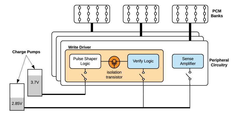
In addition to the regular read and write mode of operations, peripheral circuitry can also be in 1) idle mode, where it does not serve any request, and 2) de-stress mode, where it is powered down. Table 1 reports the operating voltages of the three logic blocks in a peripheral circuitry during read, write, idle, and de-stress operations (Redaelli et al., 2017). Voltages higher than the nominal supply are generated using the two on-chip charge pumps shown in Figure 1. These high voltages induce aging of the transistors in the peripheral circuitry logic blocks. We focus on BTI failures.
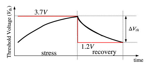
BTI is a failure mechanism in a transistor, where positive charge is trapped in the oxide-semiconductor boundary underneath the gate (Gao et al., 2017). BTI manifests as 1) decrease in drain current and transconductance, and 2) increase in off current and threshold voltage . Figure 2 illustrates the stress and recovery of the threshold voltage of a transistor on application of a high () and a low () voltage. We observe that both stress and recovery depends on the time of exposure to the corresponding voltage level. This implies that when peripheral circuitry is de-stressed, the BTI aging of its transistors partially recovers from stress. To compute the overhead due to de-stress operations, we assume that the memory controller issues a de-stress command to a memory bank once every , the de-stress interval. Each de-stress operation completes within a time interval , the de-stress cycle time. Hence, the performance overhead (i.e., data throughput loss) due to periodic de-stress is
| (1) |
The overhead due to periodic de-stress (as implemented in conservative approaches such as (Jiang et al., 2014)) is significant in current NVM devices, and it is expected to become even more performance-critical in the future as NVM chip capacity increases (Redaelli et al., 2017).
| Operating mode | Operating voltage | ||
|---|---|---|---|
| pulse shaper | verify | sense amplifier | |
| (PS) | (VF) | (SA) | |
| Read | 1.2V | 1.2V | 2.85V |
| Write (program) | 3.7V | 2.85V | 1.2V |
| Idle | 1.2V | 1.2V | 1.2V |
| De-stress | |||
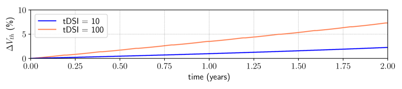
Figure 3 shows the shift in threshold voltage of a transistor in a memory bank’s peripheral circuitry when executing a microbenchmark with set to and requests, respectively.333The microbenchmark we use for this evaluation consists of alternating read and write requests to randomly selected PCM locations.
We observe that the shift in the threshold voltage is higher for larger de-stress interval . This is because when we set to a large value, the transistor is exposed to a stress voltage for a long duration between two consecutive de-stress operations. Therefore, the large parameter drift it encounters in this duration cannot be reversed during the next de-stress operation. The parameter drift continues to accumulate over time, resulting in a large shift in the threshold voltage as shown in the figure. Therefore, it is better to set the to a small value, which allows most of the parameter drifts to be reversed during each de-stress operating, resulting in a lower threshold voltage shift.
3. New Aging Model of HEBE
In this section, we introduce the new aging model of HEBE. The BTI lifetime (Song and Das, 2020; Song et al., 2020d; Balaji et al., 2019; Song et al., 2020a; Das et al., 2014a, b, c, d) of a transistor is
| (2) |
where and are material-related constants, is the activation energy, is the Boltzmann constant, is the temperature, and is the overdrive gate voltage of the transistor.444Overdrive voltage is defined as the voltage between transistor gate and source () in excess of the threshold voltage (), where is the minimum voltage required between gate and source to turn the transistor on. BTI failures can also be modeled using the Weibull distribution with a scale parameter and a slope parameter . The reliability, defined as the probability of correct operation of the transistor, at time is given by (Das et al., 2015; Huang et al., 2011; Bolchini et al., 2014; Srinivasan et al., 2004)
| (3) |
with the corresponding MTTF computed as
| (4) |
where is the Gamma function. Using the expressions for MTTF from Equations 2 and 3, and rearranging, we obtain the expression for the scale parameter as
| (5) |
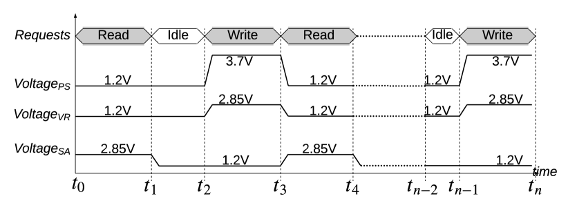
Figure 4 shows the operating voltage of PS, VR, and SA blocks in the peripheral circuitry of a memory bank when serving read and write requests from the bank. We observe that the operating voltage of the logic blocks in a memory bank’s peripheral circuit changes over time based on whether the peripheral circuit is idle or serving read or write requests. Existing aging models such as (Srinivasan et al., 2004; Das et al., 2015, 2013a) assume constant operating voltage for the logic blocks. Therefore, these models cannot be effectively used to estimate the aging in a memory bank’s peripheral circuitry.
We illustrate how we formulate aging of each of these three logic blocks in peripheral circuitry, starting with the PS logic. Let be the th time interval with and be the gate overdrive voltage in this time interval . The reliability of the PS logic at the start of execution is
| (6) |
At the end of the first interval (i.e, after servicing the first read request), the reliability of the PS logic is
| (7) |
Using the term to represent reliability degradation during this interval , the reliability at the beginning of the second interval (i.e., right after the start of the first idle period) is
| (8) |
Due to the continuity of the reliability function, we can equate Equations 7 & 8 to compute as
| (9) |
Substituting Eq. 9 in Eq. 8, reliability at time is
| (10) |
We can extend this equation to compute the reliability of the PS logic at the end of execution (i.e., after servicing the last write request from the bank in Fig. 4) as
| (11) |
We observe that Eq. 12 follows the associative property, a direct reflection of the underlying BTI failure mechanism. In other words, the aging accrued in each bank’s peripheral circuitry is independent of the order in which the reads and writes are scheduled to the bank. Eq. 12 can be rewritten using memory timing parameters as
| (13) |
where, is the row cycle time, and are the number of read and write requests, respectively, and is the number of memory clock cycles for which the PS logic is idle. and represent respectively, the aging accrued in peripheral circuitry when serving a read and a write request, and represents the aging accrued per clock cycle when the peripheral circuitry is idle. , and are called unit aging parameters, which the memory controller uses to track the aging of the PS logic in peripheral circuitry by simply recording 1) the number of read and write requests that are served from the bank, and 2) the number of idle clock cycles during workload execution. We note that these factors (read/write requests and the idle periods) cannot be known with certainty at design-time. Therefore, design-time aging estimates are not accurate.
The aging of VR and SA logic blocks (represented as and , respectively) can be computed in a similar way using Eq. 13. To obtain the overall aging, we combine these individual aging values considering the peripheral circuitry to be a series failure system, where the first instance of any logic block failing causes the entire peripheral circuit to fail. Therefore, the overall aging is
| (14) |
4. Decoupled Peripheral Circuit Architecture of HEBE
In the baseline system, when peripheral circuitry is de-stressed, its three logic blocks (PS, VR, and SA) are de-stressed simultaneously. Once de-stressed, these logic blocks take several memory cycles () before they can be used to serve memory requests again. In recent designs, cycles (Redaelli et al., 2017). Therefore, frequent de-stress operations can lead to high performance overhead (Eq. 1). To reduce this overhead, we analyze the average aging of the PS, VR, and SA blocks in a memory bank’s peripheral circuitry at the time when they are de-stressed during workload execution. Figure 5 plots these results for the workloads described in Section 6 with set to . We make the following two key observations.

First, the average aging of these logic blocks varies widely across different workloads due to the difference in memory requests. Second, at the time when a de-stress is initiated, the average aging for these three logic blocks are different and lower than the aging threshold. This is because in the baseline design, a peripheral circuit is de-stressed at its entirety, when the aging in any one of its three logic blocks exceeds the aging threshold.
Based on these observations and the connectivity of the logic blocks to the two charge pumps (see Fig. 1), we introduce an isolation transistor (M) to decouple the VR logic from the PS logic inside the write driver, allowing us to track and de-stress the logic blocks individually, as opposed to de-stressing the entire peripheral circuitry at once. Table 2 summarizes the new controls, which we enable using the isolation transistor.
Using these new decoupled control mechanism, HEBE’s request scheduler (Section 5) can de-stress logic blocks in a bank’s peripheral circuitry off the critical path of accesses, lowering bank occupancy and improving performance. We observe that the read charge pump is shared between the SA and VR logic blocks (see Figure 1). Therefore, when HEBE de-stresses the SA because SA’s aging exceeds the critical aging threshold, the VR logic also gets de-stressed, preventing the write driver from serving write requests. To address this, we exploit the decoupled program and verify-based write operations in PCM (Frulio, 2016). If a write request needs to be scheduled concurrently with the de-stress operation of SA, HEBE schedules only the program step of the write operation (which utilizes the PS block) concurrently with the de-stress operation, while the verify step is scheduled after the de-stress operation completes.
| Charge Pump Control | Peripheral Circuit Action | |||
|---|---|---|---|---|
| Read | Write | PS | VR | SA |
| Baseline Control | ||||
| Active | Active | Active | Active | Active |
| Discharged | Discharged | De-stress | De-stress | De-stress |
| Proposed Decoupled Control | ||||
| Active | Active | Active | Active | Active |
| Discharged | Active | Active | De-stress | De-stress |
| Active | Discharged | De-stress | Active | Active |
| Discharged | Discharged | De-stress | De-stress | De-stress |
5. Intelligent Memory Request Scheduler of HEBE
We design a new memory request scheduling policy to control the aging in the peripheral circuitry within each memory bank using our new aging model (Section 3) and the decoupled peripheral circuit architecture (Section 4).
5.1. High-level Overview
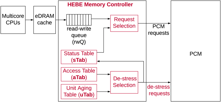
We describe HEBE in the context of DRAM-PCM hybrid memory, where embedded DRAM (eDRAM) is used as a write cache to PCM main memory as shown in Figure 6.555Even though we use eDRAM as cache to PCM in our implementation and evaluations, HEBE is applicable to any type of hybrid memory or standalone PCM memory. The baseline memory controller architecture consists of a read-write queue (rwQ) to buffer PCM requests. The key idea of HEBE’s scheduling policy is to 1) improve performance by lowering the de-stress overhead, 2) minimize wasted memory cycles during which a bank is idle with its peripheral circuitry accruing BTI aging, and 3) prevent a request from being delayed too much.
5.2. Detailed Design of HEBE
Figure 6 shows the detailed design of HEBE, which introduces five new components to the baseline memory controller design as highlighted in the figure.
The first component is the status table (sTab). HEBE uses this table to record if a memory bank is available to serve a PCM request. sTab requires one 1-bit entry for each PCM bank. For 128 banks in a 128GB PCM (see our simulation parameters in Table 3), HEBE requires 128 bits of storage for sTab.
The second component is the access table (aTab). HEBE uses this table to record the number of memory cycles for which a memory bank’s peripheral circuitry is active since the last de-stress operation of the bank. Since peripheral circuitry operates at a different voltage when it is idle than when it is serving a read or a write request, the aging model of HEBE requires the exact number of cycles for which a peripheral circuit is idle and serving read and write requests. Therefore, each aTab entry contains one 16-bit field for recording the idle cycles, and two 4-bit fields for recording the number of read and write requests. For 128GB PCM with 1GB per bank, HEBE requires 3Kb (= 128 x 24 bits) of storage.
The third component is the unit aging table (uTab). HEBE uses this table to store the unit aging parameters (Eq. 13). Since the three unit aging parameters are the same for every peripheral circuitry in PCM, there are only three 32-bit entries in this table, one for each of these parameters, requiring a total of 96 bits for uTab.666For simplicity, we have not considered process variation across different peripheral circuitry of different PCM banks.
The fourth component is the request selection. HEBE uses this component to select a request from the rwQ to schedule to PCM. Figure 7 shows the flowchart of HEBE’s request selection mechanism. After scheduling a request from the rwQ, the memory controller checks to see if the number of clock cycles for which a request is outstanding in the rwQ is smaller than the backlogging threshold (). If the backlogging threshold is exceeded, the request is de-queued and served next. Otherwise, the memory controller selects an outstanding request from the rwQ that is to a bank whose peripheral circuitry has the highest number of idle cycles since the time it served a request from the bank.
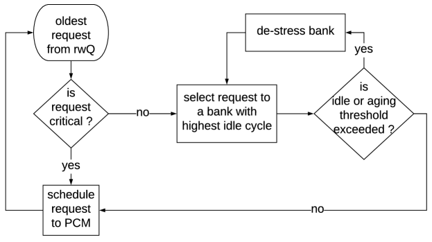
The final component is the de-stress selection logic. HEBE uses this component to schedule de-stress operations in PCM banks. For this purpose, HEBE uses two thresholds – the aging threshold () and the idle threshold (). The aging threshold is used to control the aging of peripheral circuitry in PCM in order to achieve a target lifetime. The idle threshold is used to limit the duration during which a peripheral circuit accrues aging without doing any useful work. The de-stress selection logic is also shown in Figure 7. If the selected memory request is to a bank whose peripheral circuitry exceeds either of the two thresholds, the memory controller schedules a de-stress operation to the bank. Otherwise, the request is scheduled to PCM.
5.3. Overhead of HEBE
HEBE requires a total storage of 3.2Kb for a PCM memory of 128GB capacity and 128 banks. The timing overhead of the request and de-stress selection is overlapped with the timing of an ongoing read or a write request, incurring minimal impact on the critical path of PCM read and write accesses. Therefore, HEBE’s request scheduling introduces marginal performance overhead. On the contrary, HEBE improves performance compared to other approaches by reducing the de-stress related performance bottleneck (see Section 7.1).
6. Evaluation Methodology
We evaluate HEBE for phase-change memory (PCM), one of the matured NVM technologies. We configure PCM as main memory with eDRAM as its write cache. This is similar to the architecture of IBM POWER 9 (Sadasivam et al., 2017). Our simulation framework includes the following components with parameters listed in Table 3.
-
•
Cycle-level in-house x86 multi-core simulator. We configure this to simulate 8 out-of-order cores.
- •
- •
| Processor | 8 cores, 3 GHz, out-of-order |
|---|---|
| L1-I/D cache | Private 64KB per core, 4-way |
| L2 cache | Shared, 4MB, 8-way |
| DRAM | 8GB, Micron DDR3 |
| Main Memory | 1 channel, 8 rank/channel, 8 banks/rank, 128 sub-arrays/bank, 512 rows/sub-array |
| PCM | 128GB, Micron DDR3 (Redaelli et al., 2017) |
| Main Memory | 2 channels, 1 rank/channel, 8 banks/rank, 64 partitions/bank, 128 tiles/partition, 4096 rows/tile |
Table 4 reports the timing parameters for PCM reads and writes. These parameters are based on Micron’s 128GB PCM module (Redaelli et al., 2017).
| tRCD | tRAS | tRP | tRC | ||
|---|---|---|---|---|---|
| Read | 3.75ns | 55.25ns | 1ns | 56.25ns | |
| tRCD | tBURST | tWR | tRP | tRC | |
| Write | 75ns | 15ns | 190ns | 1ns | 209.75ns |
We evaluate 10 billion instructions of ten workloads from the SPEC CPU2017 benchmarks (Bucek et al., 2018) (see Table 5).
We evaluate the following techniques.
- •
-
•
HEBE tracks the aging in CMOS transistors in peripheral circuitry of each bank and de-stresses them only when their aging exceeds the aging threshold. A peripheral circuitry is de-stressed based on the maximum aging of its logic blocks.
-
•
Decoupled-HEBE is based on HEBE. Each peripheral circuitry is decoupled to de-stress its logic blocks independently.
| single-core | 8 copies each of blender, bwaves, cactuBSSN, cam4, gcc, mcf, omnetpp, parset, roms, xalancbmk |
6.1. Aging Parameters
To compute aging, the slope parameter of Weibull distribution is set to , and the operating temperature is set to . Other fitting parameters are adjusted to achieve an MTTF of 2 years in the baseline system, corresponding to a threshold voltage shift of 10%. This is what is typically accepted as the maximum allowed degradation before timing errors begin to appear (Balaji et al., 2019; Song and Das, 2020; Song et al., 2020d; Titirsha and Das, 2020a, b; Das et al., 2012, 2013b; Das and Kumar, 2012; Das et al., 2015, 2013a).
7. Results and Analyses
7.1. Overall System Performance
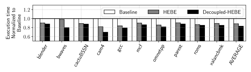
Figure 8 plots the execution time of each workload for the evaluated systems normalized to Baseline. We make the following two key observations.
First, the average execution time of HEBE is 12% lower than Baseline. This improvement is because HEBE has lower de-stress overhead than Baseline due to HEBE’s dynamic policy to opportunistically de-stress each peripheral circuitry only when its aging exceeds the aging threshold. Baseline, on the other hand, uses a fixed de-stress interval of 100 without tracking the exact aging. Second, the average execution time of Decoupled-HEBE is 6% lower than HEBE. This improvement is because Decoupled-HEBE de-stresses the logic blocks in a memory bank’s peripheral circuits off the critical path of read and write accesses from the bank, reducing bank occupancy and improving performance.
7.2. Overall MTTF
Figure 9 plots the MTTF of each workload for the evaluated systems normalized to Baseline. We make the following two key observations.
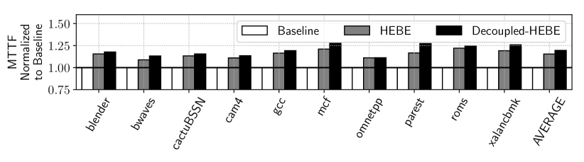
First, the average MTTF of HEBE is 16% higher than Baseline. This improvement is because 1) HEBE does not allow the aging of any peripheral circuitry in PCM to exceed the aging threshold and 2) the aging-aware access scheduling policy of HEBE minimizes the number of wasted memory cycles for which a peripheral circuitry accrues aging while being idle. Second, the average MTTF of Decoupled-HEBE is 3.4% higher than HEBE. This improvement is because HEBE needs to wait for an ongoing PCM read or write request to complete before it can schedule the de-stress operation of a peripheral circuitry. Therefore, the circuitry continues to age before it is eventually de-stressed, lowering its MTTF. On the other hand, Decoupled-HEBE can schedule the de-stress operation of a logic block in a bank’s peripheral circuitry independently and in parallel to ongoing read and write requests to the bank. Therefore, the MTTF of Decoupled-HEBE is higher than HEBE.
7.3. De-stress Overhead
Figure 10 plots the de-stress overhead (Eq. 1) of each workload for each evaluated system normalized to Baseline. We make the following two key observations.
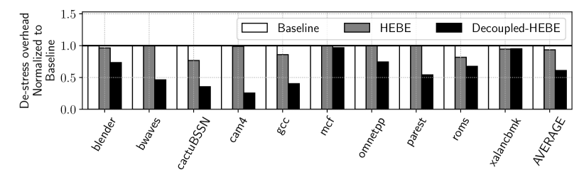
First, the average de-stress overhead of HEBE is 6.6% lower than Baseline. This improvement is because HEBE increases the de-stress interval () by accurately tracking the aging of each peripheral circuitry dynamically, de-stressing it only when aging exceeds a threshold. Baseline uses a fixed of 100. Second, the average de-stress overhead of Decoupled-HEBE is 35% lower than HEBE. This improvement is due to the reduction of the de-stress cycle time (), which is achieved by de-stressing the logic blocks in a bank’s peripheral circuitry independently and in parallel to ongoing read and write requests to the bank.
7.4. Effect of Aging Threshold
Figure 11 reports the execution time and aging of each of our workloads using HEBE, normalized to Baseline. The height of a bar represents HEBE’s result with the default aging threshold of 1000 units. An error bar represents the variation obtained by changing the aging threshold from 500 units to 2000 units. We make the following observation.

When we set a stricter aging threshold (e.g., 500 units), execution time increases and aging decreases. This is because when the aging threshold is lowered, the high-voltage exposure time of the peripheral circuitry in each memory bank reduces, reducing the accrued aging. However, performance degrades due to the high de-stress overhead (see Eq. 1). Conversely, when we relax the aging threshold (e.g., 2000 units), the de-stress interval increases, reducing the de-stress overhead and increasing performance. However, aging is now higher because of longer exposure to high-voltage stress.
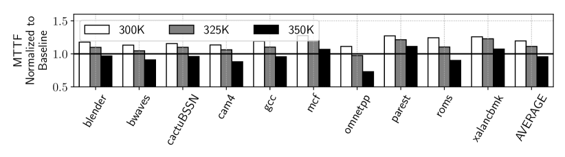
7.5. Temperature Dependency
Figure 12 plots MTTF of Decoupled-HEBE at 300K, 325K, and 350K normalized to Baseline at 300K for each evaluated application. We observe that MTTF decreases with increase in temperature. MTTF at 325K and 350K are higher than at 300K by an average of 7% and 26%, respectively. These results follow directly from our aging formulation, which incorporates temperature using the scaling parameter in Eq. 5. This parameter grows exponentially with temperature, resulting in a corresponding exponential increase in aging. More aging leads to larger shift in threshold voltage.
8. Related Works
To our knowledge, this is the first work that exploits a workload’s access characteristics to dynamically control the length of the de-stress interval of peripheral circuitry in each memory bank, improving both performance and MTTF of PCM-based main memory. Many works propose optimizations for PCM. Recent examples include architecture optimization (Qureshi et al., 2009; Lee et al., 2009; Yavits et al., 2020), performance and energy optimization (Yoon et al., 2012, 2014; Song et al., 2019, 2020b; Kim et al., 2019a; Arjomand et al., 2016), wear leveling (Song et al., 2020a; Zhang and Sun, 2017; Zhang et al., 2018), and memory controller optimizations (Zhao et al., 2014). See (Xia et al., 2015) for a survey of these and other similar approaches. HEBE can be combined with most of these techniques.
Many works propose memory latency reduction, refresh optimization, energy reduction, and request scheduling methods to enhance system performance, fairness, quality of service, or security (Ren et al., 2015; Seshadri et al., 2015; Subramanian et al., 2014, 2016; Chang et al., 2017; Khan et al., 2016; Chang et al., 2016; Liu et al., 2012; Usui et al., 2016; Ausavarungnirun et al., 2012; Rixner et al., 2000; Chang et al., 2014; Kim et al., 2010a; Mutlu and Moscibroda, 2008; Kim et al., 2010b; Meza et al., 2012b; Lu et al., 2014; Pelley et al., 2014; Ipek et al., 2008; Hassan et al., 2016; Lee et al., 2015; Qureshi et al., 2015; Patel et al., 2017; Deng et al., 2011; David et al., 2011; Kim et al., 2018a, b, 2019b; Mutlu and Moscibroda, 2007; Nesbit et al., 2006; Rixner, 2004). None of these works consider aging of phase change memory in their scheduling decisions. Our aging-aware scheduling mechanism can be incorporated into other memory controller designs that aim to improve other metrics.
9. Conclusions
We introduce HEBE, a new mechanism that can dynamically track and control the aging of transistors in peripheral circuitry of each memory bank, improving both performance and aging of NVM-based main memory. HEBE is built on three novel contributions. First, we propose a new, accurate analytical model to dynamically track aging in response to the memory controller’s request scheduling decisions. Second, we develop a new, intelligent request scheduler that exploits this aging model at run time to decide when peripheral circuitry in NVM must be de-stressed. Third, we decouple logic blocks in peripheral circuitry operating at different voltages, allowing these blocks to be de-stressed independently and off the critical path of execution, improving performance. We evaluate HEBE for DRAM-NVM hybrid main memory and show the significant performance and MTTF improvement. We conclude that HEBE is a simple yet powerful mechanism to dynamically manage the aging in non-volatile main memory, and improve both performance and lifetime via its intelligent request scheduling decisions.
Acknowledgments
This work is supported by the National Science Foundation Faculty Early Career Development Award CCF-1942697 (CAREER: Facilitating Dependable Neuromorphic Computing: Vision, Architecture, and Impact on Programmability).
References
- Arjomand et al. (2016) M. Arjomand et al., “Boosting access parallelism to PCM-based main memory,” in ISCA, 2016.
- Ausavarungnirun et al. (2012) R. Ausavarungnirun et al., “Staged memory scheduling: Achieving high performance and scalability in heterogeneous systems,” in ISCA, 2012.
- Balaji et al. (2019) A. Balaji et al., “A framework to explore workload-specific performance and lifetime trade-offs in neuromorphic computing,” CAL, 2019.
- Balaji et al. (2020a) A. Balaji et al., “Mapping spiking neural networks to neuromorphic hardware,” TVLSI, 2020.
- Balaji et al. (2020b) A. Balaji et al., “Enabling resource-aware mapping of spiking neural networks via spatial decomposition,” ESL, 2020.
- Bolchini et al. (2014) C. Bolchini et al., “A lightweight and open-source framework for the lifetime estimation of multicore systems,” in ICCD, 2014.
- Bucek et al. (2018) J. Bucek et al., “SPEC CPU2017: Next-generation compute benchmark,” in ICPE, 2018.
- Burr et al. (2017) G. W. Burr et al., “Neuromorphic computing using non-volatile memory,” Advances in Physics: X, 2017.
- Chandrasekar et al. (2012) K. Chandrasekar et al., “DRAMPower: Open-source DRAM power & energy estimation tool,” URL: http://www. drampower. info, 2012.
- Chang et al. (2016) K. K. Chang et al., “Understanding latency variation in modern DRAM chips: Experimental characterization, analysis, and optimization,” in SIGMETRICS, 2016.
- Chang et al. (2017) K. K. Chang et al., “Understanding reduced-voltage operation in modern DRAM devices: Experimental characterization, analysis, and mechanisms,” in SIGMETRICS, 2017.
- Chang et al. (2014) K. K.-W. Chang et al., “Improving DRAM performance by parallelizing refreshes with accesses,” in HPCA, 2014.
- Das and Kumar (2012) A. Das et al., “Fault-aware task re-mapping for throughput constrained multimedia applications on NoC-based MPSoCs,” in RSP, 2012.
- Das et al. (2012) A. Das et al., “Fault-tolerant network interface for spatial division multiplexing based network-on-chip,” in ReCoSoC, 2012.
- Das et al. (2013a) A. Das et al., “Aging-aware hardware-software task partitioning for reliable reconfigurable multiprocessor systems,” in CASES, 2013.
- Das et al. (2013b) A. Das et al., “Energy-aware dynamic reconfiguration of communication-centric applications for reliable MPSoCs,” in ReCoSoC, 2013.
- Das et al. (2014d) A. Das et al., “Energy-aware task mapping and scheduling for reliable embedded computing systems,” TECS, 2014.
- Das et al. (2014a) A. Das et al., “Temperature aware energy-reliability trade-offs for mapping of throughput-constrained applications on multimedia MPSoCs,” in DATE, 2014.
- Das et al. (2014b) A. Das et al., “Combined DVFS and mapping exploration for lifetime and soft-error susceptibility improvement in MPSoCs,” in DATE, 2014.
- Das et al. (2014c) A. Das et al., “Reinforcement learning-based inter-and intra-application thermal optimization for lifetime improvement of multicore systems,” in DAC, 2014.
- Das et al. (2015) A. Das et al., “Reliability and energy-aware mapping and scheduling of multimedia applications on multiprocessor systems,” TPDS, 2015.
- Das et al. (2018) A. Das et al., “VRL-DRAM: Improving DRAM performance via variable refresh latency,” in DAC, 2018.
- David et al. (2011) H. David et al., “Memory power management via dynamic voltage/frequency scaling,” in ICAC, 2011.
- Deng et al. (2011) Q. Deng et al., “MemScale: Active low-power modes for main memory,” in ASPLOS, 2011.
- Frulio (2016) M. Frulio, “Adaptive non-volatile memory programming,” 2016, US Patent.
- Gao et al. (2017) R. Gao et al., “NBTI-Generated defects in nanoscaled devices: Fast characterization methodology and modeling,” TED, 2017.
- Hassan et al. (2016) H. Hassan et al., “ChargeCache: Reducing DRAM latency by exploiting row access locality,” in HPCA, 2016.
- Hisamoto et al. (2000) D. Hisamoto et al., “FinFET-a self-aligned double-gate MOSFET scalable to 20 nm,” TED, 2000.
- Huang et al. (2011) L. Huang et al., “On task allocation and scheduling for lifetime extension of platform-based mpsoc designs,” TPDS, 2011.
- Ipek et al. (2008) E. Ipek et al., “Self-optimizing memory controllers: A reinforcement learning approach,” in ISCA, 2008.
- Jiang et al. (2014) L. Jiang et al., “A low power and reliable charge pump design for phase change memories,” in ISCA, 2014.
- Khan et al. (2016) S. Khan et al., “PARBOR: An efficient system-level technique to detect data-dependent failures in DRAM,” in DSN, 2016.
- Kim et al. (2018b) J. Kim et al., “Solar-DRAM: Reducing DRAM access latency by exploiting the variation in local bitlines,” in ICCD, 2018.
- Kim et al. (2018a) J. S. Kim et al., “The DRAM latency PUF: Quickly evaluating physical unclonable functions by exploiting the latency-reliability tradeoff in modern commodity DRAM devices,” in HPCA, 2018.
- Kim et al. (2019b) J. S. Kim et al., “D-RaNGe: Using commodity DRAM devices to generate true random numbers with low latency and high throughput,” in HPCA, 2019.
- Kim et al. (2020) J. S. Kim et al., “Revisiting RowHammer: An experimental analysis of modern DRAM devices and mitigation techniques,” in ISCA, 2020.
- Kim et al. (2019a) N. Kim et al., “LL-PCM: Low-latency phase change memory architecture,” in DAC, 2019.
- Kim et al. (2010a) Y. Kim et al., “ATLAS: A scalable and high-performance scheduling algorithm for multiple memory controllers,” in HPCA, 2010.
- Kim et al. (2010b) Y. Kim et al., “Thread cluster memory scheduling: Exploiting differences in memory access behavior,” in MICRO, 2010.
- Kim et al. (2014) Y. Kim et al., “Flipping bits in memory without accessing them: An experimental study of DRAM disturbance errors,” in ISCA, 2014.
- Kim et al. (2016) Y. Kim et al., “Ramulator: A fast and extensible DRAM simulator.” CAL, 2016.
- Kim et al. (2012) Y. Kim et al., “A case for exploiting subarray-level parallelism (SALP) in DRAM,” in ISCA, 2012.
- Kraak et al. (2019) D. Kraak et al., “Parametric and Functional Degradation Analysis of Complete 14-nm FinFET SRAM,” TVLSI, 2019.
- Kültürsay et al. (2013) E. Kültürsay et al., “Evaluating STT-RAM as an energy-efficient main memory alternative,” in ISPASS, 2013.
- Lalam and Shen (2019) A. Lalam et al., “Non-volatile dual in-line memory module (NVDIMM) multichip package,” US Patent 10,199,364, 2019.
- Lee et al. (2010b) B. Lee et al., “Phase-change technology and the future of main memory,” IEEE Micro, 2010.
- Lee et al. (2009) B. Lee et al., “Architecting phase change memory as a scalable DRAM alternative,” in ISCA, 2009.
- Lee et al. (2010a) B. Lee et al., “Phase change memory architecture and the quest for scalability,” CACM, 2010.
- Lee et al. (2013) D. Lee et al., “Tiered-latency DRAM: A low latency and low cost DRAM architecture,” in HPCA, 2013.
- Lee et al. (2015) D. Lee et al., “Adaptive-latency DRAM: Optimizing DRAM timing for the common-case,” in HPCA, 2015.
- Liu et al. (2012) J. Liu et al., “RAIDR: Retention-aware intelligent DRAM refresh,” in ISCA, 2012.
- Lu et al. (2014) Y. Lu et al., “Loose-ordering consistency for persistent memory,” in ICCD, 2014.
- Mallik et al. (2017) A. Mallik et al., “Design-technology co-optimization for OxRRAM-based synaptic processing unit,” in VLSIT, 2017.
- Mandelman et al. (2002) J. A. Mandelman et al., “Challenges and future directions for the scaling of dynamic random-access memory (DRAM),” IBM JRD, 2002.
- Meza et al. (2012b) J. Meza et al., “Enabling efficient and scalable hybrid memories using fine-granularity DRAM cache management,” CAL, 2012.
- Meza et al. (2012a) J. Meza et al., “A case for small row buffers in non-volatile main memories,” in ICCD, 2012.
- Meza et al. (2013) J. Meza et al., “A case for efficient hardware/software cooperative management of storage and memory,” in WEED, 2013.
- Meza et al. (2018) J. Meza et al., “Evaluating row buffer locality in future non-volatile main memories,” arXiv, 2018.
- Mutlu (2013) O. Mutlu, “Memory scaling: A systems architecture perspective,” in IMW, 2013.
- Mutlu (2017) O. Mutlu, “The rowhammer problem and other issues we may face as memory becomes denser,” in DATE, 2017.
- Mutlu and Kim (2019) O. Mutlu et al., “Rowhammer: A retrospective,” TCAD, 2019.
- Mutlu and Moscibroda (2007) O. Mutlu et al., “Stall-time fair memory access scheduling for chip multiprocessors,” in MICRO, 2007.
- Mutlu and Moscibroda (2008) O. Mutlu et al., “Parallelism-aware batch scheduling: Enhancing both performance and fairness of shared DRAM systems,” in ISCA, 2008.
- Mutlu and Subramanian (2015) O. Mutlu et al., “Research problems and opportunities in memory systems,” SUFI, 2015.
- Nesbit et al. (2006) K. J. Nesbit et al., “Fair queuing memory systems,” in MICRO, 2006.
- Patel et al. (2017) M. Patel et al., “The reach profiler (REAPER) enabling the mitigation of DRAM retention failures via profiling at aggressive conditions,” in ISCA, 2017.
- Pelley et al. (2014) S. Pelley et al., “Memory persistency,” in ISCA, 2014.
- Poremba et al. (2015) M. Poremba et al., “Nvmain 2.0: A user-friendly memory simulator to model (non-) volatile memory systems,” CAL, 2015.
- Qureshi (2011) M. K. Qureshi, “Pay-As-You-Go: Low-overhead hard-error correction for phase change memories,” in MICRO, 2011.
- Qureshi et al. (2009) M. K. Qureshi et al., “Scalable high performance main memory system using phase-change memory technology,” in ISCA, 2009.
- Qureshi et al. (2010) M. K. Qureshi et al., “Improving read performance of phase change memories via write cancellation and write pausing,” in HPCA, 2010.
- Qureshi et al. (2015) M. K. Qureshi et al., “AVATAR: A variable-retention-time (VRT) aware refresh for DRAM systems,” in DSN, 2015.
- Redaelli et al. (2017) A. Redaelli et al., Phase Change Memory. Springer, 2017.
- Ren et al. (2015) J. Ren et al., “ThyNVM: Enabling software-transparent crash consistency in persistent memory systems,” in MICRO, 2015.
- Rixner (2004) S. Rixner, “Memory controller optimizations for web servers,” in MICRO, 2004.
- Rixner et al. (2000) S. Rixner et al., “Memory access scheduling,” in ISCA, 2000.
- Sadasivam et al. (2017) S. K. Sadasivam et al., “IBM POWER 9 processor architecture,” IEEE Micro, 2017.
- Seshadri and Mutlu (2019) V. Seshadri et al., “In-DRAM bulk bitwise execution engine,” arXiv, 2019.
- Seshadri et al. (2015) V. Seshadri et al., “Gather-scatter DRAM: In-DRAM address translation to improve the spatial locality of non-unit strided accesses,” in MICRO, 2015.
- Song and Das (2020) S. Song et al., “A case for lifetime reliability-aware neuromorphic computing,” in MWSCAS, 2020.
- Song et al. (2019) S. Song et al., “Enabling and exploiting partition-level parallelism (PALP) in phase change memories,” TECS, 2019.
- Song et al. (2020c) S. Song et al., “Compiling spiking neural networks to neuromorphic hardware,” in LCTES, 2020.
- Song et al. (2020d) S. Song et al., “Improving dependability of neuromorphic computing with non-volatile memory,” in EDCC, 2020.
- Song et al. (2020b) S. Song et al., “Improving phase change memory performance with data content aware access,” in ISMM, 2020.
- Song et al. (2020a) S. Song et al., “Exploiting inter- and intra-memory asymmetries for data mapping in hybrid tiered-memories,” in ISMM, 2020.
- Srinivasan et al. (2004) J. Srinivasan et al., “The case for lifetime reliability-aware microprocessors,” in ISCA, 2004.
- Subramanian et al. (2014) L. Subramanian et al., “The blacklisting memory scheduler: Achieving high performance and fairness at low cost,” in ICCD, 2014.
- Subramanian et al. (2016) L. Subramanian et al., “BLISS: Balancing performance, fairness and complexity in memory access scheduling,” TPDS, 2016.
- Titirsha and Das (2020b) T. Titirsha et al., “Reliability-performance trade-offs in neuromorphic computing,” in CUT, 2020.
- Titirsha and Das (2020a) T. Titirsha et al., “Thermal-aware compilation of spiking neural networks to neuromorphic hardware,” in LCPC, 2020.
- Usui et al. (2016) H. Usui et al., “DASH: Deadline-aware high-performance memory scheduler for heterogeneous systems with hardware accelerators,” TACO, 2016.
- Weckx et al. (2014) P. Weckx et al., “Non-Monte-Carlo methodology for high-sigma simulations of circuits under workload-dependent BTI degradation-application to 6T SRAM,” in IRPS, 2014.
- Wikipedia contributors (2020) Wikipedia contributors, “Hebe (mythology) — Wikipedia, the free encyclopedia,” 2020, [Online; accessed 14-Aug-2020].
- Wong et al. (2010) H.-S. P. Wong et al., “Phase change memory,” Proceedings of the IEEE, 2010.
- Xia et al. (2015) F. Xia et al., “A survey of phase change memory systems,” JCST, 2015.
- Xiong et al. (2016) F. Xiong et al., “Towards ultimate scaling limits of phase-change memory,” in IEDM, 2016.
- Yavits et al. (2020) L. Yavits et al., “WoLFRaM: Enhancing wear-leveling and fault tolerance in resistive memories using programmable address decoders,” in ICCD, 2020.
- Yilmaz et al. (2013) C. Yilmaz et al., “Modeling of NBTI-recovery effects in analog CMOS circuits,” in IRPS, 2013.
- Yoon et al. (2012) H. Yoon et al., “Row buffer locality aware caching policies for hybrid memories,” in ICCD, 2012.
- Yoon et al. (2014) H. Yoon et al., “Efficient data mapping and buffering techniques for multilevel cell phase-change memories,” TACO, 2014.
- Zhang et al. (2018) J. Zhang et al., “RETROFIT: Fault-aware wear leveling,” CAL, 2018.
- Zhang and Sun (2017) X. Zhang et al., “Toss-up wear leveling: Protecting phase-change memories from inconsistent write patterns,” in DAC, 2017.
- Zhao et al. (2014) J. Zhao et al., “FIRM: Fair and high-performance memory control for persistent memory systems,” in MICRO, 2014.
- Zuravleff and Robinson (1997) W. K. Zuravleff et al., “Controller for a synchronous DRAM that maximizes throughput by allowing memory requests and commands to be issued out of order,” US Patent 5,630,096, 1997.