Rotational Error Metrics for Quadrotor Control
Abstract
We analyze and experimentally compare various rotational error metrics for use in quadrotor controllers. Traditional quadrotor attitude controllers have used Euler angles or the full rotation to compute an attitude error and scale that to compute a control response. Recently, several works have shown that prioritizing quadrotor tilt, or thrust vector error, in the attitude controller leads to improved position control, especially in situations with large yaw error. We provide a catalog of proposed rotational metrics, place them into the same framework, and show that we can independently reason about and design the magnitude of the response and the direction of the response. Existing approaches mainly fall into two categories: (1) metrics that induce a response in the shortest direction to correct the full rotation error and (2) metrics that combine a response in the shortest direction to correct tilt error with the shortest direction to correct yaw error. We show experimental results to highlight the salient differences between the rotational error metrics. See https://alspitz.github.io/roterrormetrics.html for an interactive simulation visualizing the experiments performed.
Index Terms:
quadrotor, control, nonlinear controls, dynamic inversion, attitude control, rotation representationI Introduction
We analyze and compare various attitude error metrics that have been proposed for use in quadrotor attitude controllers.
The most common control structure for multirotors is cascaded, shown in Figure 1, where a position controller generates a desired attitude that an attitude controller then attempts to track.
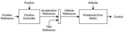
For brevity, we consider regulation, not trajectory tracking, but all of the results here can be extended to work for trajectory tracking, where the desired angular velocity and the desired angular acceleration are nonzero.
The structure of quadrotor attitude controllers that we consider is a PD controller on rotational error, as defined by a rotational error metric , scaled by a diagonal attitude gain matrix , and angular velocity , scaled by a diagonal angular velocity gain matrix .
| (1) |
Several works in the literature have noted that, since the quadrotor’s position dynamics depend solely on its tilt, or body -axis, it makes sense to prioritize vehicle tilt over vehicle yaw [1, 2, 3, 4, 5]. In this work, we confirm this, and show that such metrics amount to inducing a response in the direction of the cross product between the current and desired body -axes, along with a response around the body -axis. We show that this decomposition linearizes the vehicle error response better than the traditional attitude controller, which uses the full rotation error. Following straight paths in the presence of large tracking error can be beneficial for overall control performance.
II Rotational Error Metrics
II-A Preliminaries
In this section, we place various controllers used in the literature in the framework described above. First, as in Mueller [3], we define rotational error as
| (2) |
and its corresponding angle and axis as and .
The vehicle attitude transforms vectors from the body frame into the fixed frame, and is represented using a matrix whose columns , , and are the coordinate frames axes of the body.
| (3) |
We define the thrust vector error as the rotation between the -axes of the current and desired attitude, along with its associated angle and axis . This rotation can be defined via its angle and axis in terms of the full rotation error as shown below [3].
| (4) | ||||
| (5) |
To help visualize , note that it is just the normalized cross product of the desired -axis with the current -axis of the body , expressed in the body frame. As a result, .
| (6) |
We define the yaw error as the remaining error around the body -axis, i.e. the rotation needed to align the current rotation to the desired rotation after aligning the axes.
| (7) |
represents the angle associated with and represents the axis, which is either or , and thus perpendicular to .
II-B Full Rotation Metrics
A rotational error metric directly in is used in [6, 7, 8]. As shown in [3], this metric is proportional to the sine of the angle error and in the direction of the shortest path .
| (8) |
Lee [9] notes the issues with using a rotational error metric that is proportional to the sine of the error, namely that the response is strongest at an error of and weakens as the error increases, reaching zero at an error of . While this ensures smoothness of the response, it results in slow convergence when the error is high. Lee [9] proposes rescaling the rotational error. 111We add a factor of 2 to match the linearization around of (8).
| (9) |
| (10) |
(10) is mathematically equivalent to the rotational error used in Fresk and Nikolakopoulos [10], which is the axis component of the error quaternion. The axis component of a quaternion is the sine of the half angle multiplied by the axis.
Similarly, one can use an error response that is directly proportional to the angle.
| (11) |
II-C Thrust Vector – Yaw Decomposition Metrics
In this section we will characterize the attitude controls used by works that decompose attitude into a thrust vector and yaw, also known as “reduced attitude control”, with an emphasis on the control around the body and axes. Define, .
Kooijman et al. [4] decomposes the attitude representation into , which amounts to controlling the thrust vector direction, an element of , independently from the rotation around the thrust vector, an element of . The control response around the and axes222For simplicity, we omit the yaw controller from Kooijman et al. [4]. in Kooijman et al. [4] is given as
| (12) | ||||
| (13) | ||||
| (14) |
with defined as
| (15) |
| (16) |
Assuming a P controller for angular velocity, from (16) we can extract the rotational error metric as
| (17) |
(17) has the interesting property that the magnitude of the response is maximum at an angle of and remains constant as the angle increases from to . For , (17) is equivalent to (8) for axis-aligned errors.
Brescianini and D’Andrea [11] also decomposes the thrust vector and the yaw, but does so using two quaternions. The final control law is a sum of a quaternion error representing the error in the thrust direction and a quaternion error representing the error in the angle around the body -axis. The use of quaternions implies that the rotational error metric is proportional to the sine of the half angle for both the thrust vector error and the yaw error. The resulting rotational error metric is shown below, with again, a factor of 2 added to match linearizations with the other metrics.
| (18) |
Mueller [3] proposes a new rotational error metric that is effectively a linear interpolation between (11) and only controlling the thrust vector. The rotational error metric is shown below, with used to weight the control of the yaw angle.
| (19) |
Unlike, (17) and (18), (19) doesn’t decouple the yaw control from the thrust vector control for . As we will show below, this leads to suboptimal performance in certain situations with large angle errors. As an alternative, we propose to use the decoupling metric from (18), but proportional to the angle, as shown below.
| (20) |
| Scaling / Direction | Full: | Decomposed: |
|---|---|---|
| : [6, 7, 8] | 333For .: [4, 5] | |
| : [9, 10] | : [1, 2, 3, 11] | |
| , 444For .: [3] | : Proposed |
Table I provides a tabulated summary of rotational error metric configurations discussed.
III Experiments
To evaluate the rotational error metrics for the purposes of quadrotor control, we use the following three scenarios.
-
1.
Direction change.
-
2.
Axis-aligned step with large initial yaw error.
-
3.
Diagonal step.
For the last two experiments, we additionally compare against an Euler angle-based rotational error metric, defined using the Z-Y-X convention. The yaw , pitch , and roll , define a rotation matrix using the following map , with and .
| (21) |
The rotational error metric is then defined using the inverse of , making sure to compute the shortest angular distance for each angle.
| (22) |
III-A Direction Change
The quadrotor is tasked to reach a goal position at after starting at the origin with a velocity of and an initial roll angle of degrees. This initial condition is designed to induce an initial roll error greater than , so that differences in the rotational error metric responses at large angle errors are highlighted.
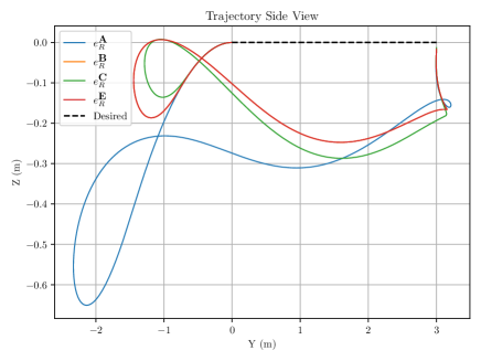
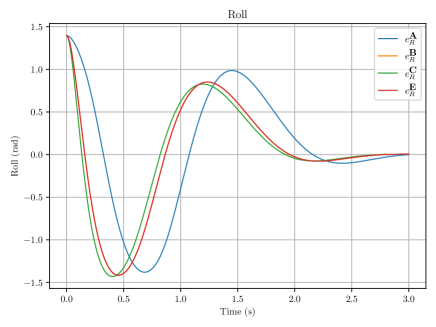
Figure 2 shows the resulting side view and roll trajectory. The important thing to note here is that the rotational error metric , which has a response proportional to the sine of the angle error, converges slower than the other metrics. This example shows that metrics that induce a response proportional to the sine of the angle can suffer from slow convergence when there is large attitude error.
III-B Step with Yaw Error
In this test, the quadrotor executes a position step and yaw step simultaneously. The vehicle starts at the origin at a yaw of and moves to at a yaw of .
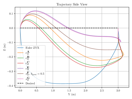
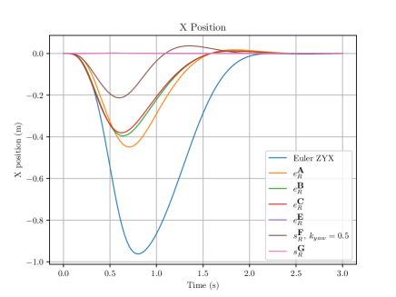
Figure 3 shows the side view and position during the experiment. We see that metrics that use the full rotation error, result in trajectories that do not maintain the desired position. Metrics that decompose the response, E and G, maintain the desired position.
III-C Diagonal Step
In this test, we show that yaw error is not necessary for the rotational error metrics that do not decouple the thrust vector from yaw to exhibit suboptimal performance. The quadrotor is given a diagonal step from the origin to , with a desired yaw of for the duration of the test.
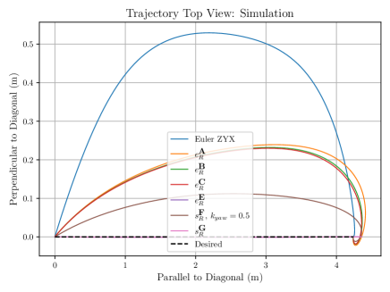
Figure 4 shows the top view of the trajectories followed during the experiment for the various error metrics. Metrics that use the full rotation error, A, B, C, and F, deviate from the diagonal path. This is because the shortest path in from the identity to an orientation that results in the vehicle accelerating diagonally at the same yaw angle, takes the vehicle through orientations that accelerate in directions other than the diagonal direction. In other words, the thrust vector projected onto the horizontal plane does not point in the direction of the desired position.
Metrics that decompose the error into a thrust vector component and a yaw component, E and G, follow the straight-line diagonal path to the desired position.
IV Discussion
We have shown that many quadrotor attitude controllers in the literature can be neatly characterized using their rotational error metrics’ scaling and direction.
We have shown that rotational error metrics that decompose the attitude error in a thrust vector component and a yaw component provide superior control performance than those that use the full attitude error for (1) simultaneous large errors in position and yaw and (2) diagonal steps.
References
- Brescianini et al. [2013] D. Brescianini, M. Hehn, and R. D’Andrea, “Nonlinear Quadrocopter Attitude Control: Technical Report,” ETH Zurich, Tech. Rep., 2013. https://hdl.handle.net/20.500.11850/154099
- Faessler et al. [2015] M. Faessler, F. Fontana, C. Forster, and D. Scaramuzza, “Automatic re-initialization and failure recovery for aggressive flight with a monocular vision-based quadrotor,” in 2015 IEEE International Conference on Robotics and Automation (ICRA), May 2015, pp. 1722–1729. https://ieeexplore.ieee.org/document/7139420/
- Mueller [2018] M. W. Mueller, “Multicopter attitude control for recovery from large disturbances,” arXiv:1802.09143 [cs], Feb. 2018. https://arxiv.org/abs/1802.09143
- Kooijman et al. [2019] D. Kooijman, A. P. Schoellig, and D. J. Antunes, “Trajectory Tracking for Quadrotors with Attitude Control on ,” in 2019 18th European Control Conference (ECC), Jun. 2019, pp. 4002–4009. https://ieeexplore.ieee.org/document/8795755
- Gamagedara et al. [2019] K. Gamagedara, M. Bisheban, E. Kaufman, and T. Lee, “Geometric Controls of a Quadrotor UAV with Decoupled Yaw Control,” in 2019 American Control Conference (ACC), Jul. 2019, pp. 3285–3290. https://ieeexplore.ieee.org/document/8815189
- Lee et al. [2010] T. Lee, M. Leoky, and N. H. McClamroch, “Geometric tracking control of a quadrotor UAV on SE(3),” in 49th IEEE Conference on Decision and Control (CDC), Dec. 2010, pp. 5420–5425. https://ieeexplore.ieee.org/document/5717652
- Mellinger and Kumar [2011] D. Mellinger and V. Kumar, “Minimum snap trajectory generation and control for quadrotors,” in 2011 IEEE International Conference on Robotics and Automation (ICRA), 2011, pp. 2520–2525. https://ieeexplore.ieee.org/abstract/document/5980409/
- Goodarzi et al. [2013] F. Goodarzi, D. Lee, and T. Lee, “Geometric nonlinear PID control of a quadrotor UAV on SE(3),” in 2013 European Control Conference (ECC), Jul. 2013, pp. 3845–3850. https://ieeexplore.ieee.org/document/6669644
- Lee [2012] T. Lee, “Exponential stability of an attitude tracking control system on SO(3) for large-angle rotational maneuvers,” Systems & Control Letters, vol. 61, no. 1, pp. 231–237, Jan. 2012. https://www.sciencedirect.com/science/article/pii/S0167691111002829
- Fresk and Nikolakopoulos [2013] E. Fresk and G. Nikolakopoulos, “Full quaternion based attitude control for a quadrotor,” in 2013 European Control Conference (ECC), Jul. 2013, pp. 3864–3869. https://ieeexplore.ieee.org/document/6669617/
- Brescianini and D’Andrea [2020] D. Brescianini and R. D’Andrea, “Tilt-Prioritized Quadrocopter Attitude Control,” IEEE Transactions on Control Systems Technology, vol. 28, no. 2, pp. 376–387, Mar. 2020. https://ieeexplore.ieee.org/document/8556372/