Performance Analysis of an Interference-Limited RIS-Aided Network
Abstract
In this work, the performance of reconfigurable intelligent surface (RIS)-aided communication systems corrupted by the co-channel interference (CCI) at the destination is investigated. Assuming Rayleigh fading and equal-power CCI, we present the analysis for the outage probability (OP), average bit error rate (BER), and ergodic capacity. In addition, an asymptotic outage analysis is carried in order to obtain further insights. Our analysis shows that the number of reflecting elements as well as the number of interferers have a great impact on the overall system performance.
Index Terms:
Average bit error rate (BER), average channel capacity, co-channel interference (CCI), outage probability (OP), reconfigurable intelligent surfaces (RISs).I Introduction
A new disruptive technology, called reconfigurable intelligent surface (RIS), has recently emerged in the research community. The RIS is an artificial surface composed of electromagnetic (EM) materials that is electronically controlled by low-cost electronic devices. Owing to its unique functions, RIS can efficiently customize the wireless environment, thereby maximizing the signal quality at the receiver [1]. Compared with other competing technologies, it is worth noting that RIS does not require encoding and decoding operations during the signal transmission. In addition, it does not create new waves and can change the shape of the wireless signal through soft programming.
Recently, several works have investigated the incorporation of RISs in wireless systems. Specifically, the authors in [2] studied the joint optimization of transmitting source and RIS beams in multiple-input single-output (MISO) communication systems. In [3], the authors studied the optimization of joint transmission and reflected beamforming in RIS-assisted multiuser systems. In [4], the application of RISs in downlink multiuser communications was examined, while [5] provided an accurate analytical results for the coverage, probability of signal-to-noise ratio (SNR) gain, and delay outage rate of RIS-assisted wireless communication systems. Moreover, the analysis in [6] showed that using RISs has a positive effect on improving the secrecy performance of wireless systems. A performance analysis for the application of RISs in a dual-hop free-space optical (FSO)/radio-frequency (RF) system was carried out in [7]. Finally, [8] analyzed the performance of RIS-aided unmanned aerial vehicle (UAV) communication relaying systems. However, for all we know, the impact of co-channel interference (CCI) in RIS-aided communication system remains to be investigated in the literature yet, which motivates this new work.
In this paper, the performance of RIS-assisted interference-limited communication systems with CCI at the destination is studied. To this end, we first derive the statistical distribution of the effective signal-to-interference ratio (SIR) expression and, based on it, exact analysis for the outage probability (OP), average bit error rate (BER), and average channel capacity are presented. To clearly show the effects of the interference and power levels on the system performance, an asymptotic outage expression is also derived. Our results reveal that the number of reflecting meta-surfaces as well as the number of interferers have a significant impact on the overall system performance.
II System and Channel Models
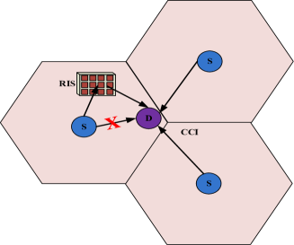
Our considered system model can be found in Fig. 1, where a single-antenna source (S) intends to communicate with a single-antenna destination (D) via an RIS formed by reflecting elements. The terminal D is affected by independent equal-power interferers. Such a scenario finds applicability in cases where the RIS and S are located at the center of a cellular network, whereas D is located at its border. We assume that direct link transmission between S and D does not exist due to obstacles. Moreover, it is assumed that the considered system operates in an interference-limited regime so that the effect of noise on the overall performance can be negligible. Similar to [1], we assume that the RIS has the ability to obtain the full channel state information (CSI). Thus, the resulting signal at D can be written as
| (1) |
where denotes the average transmitted power per symbol at the S, is the source signal, denotes the transmit power of the interferers, and and are, respectively, the channel coefficient suffering from the Rayleigh fading and unit energy signal for the interferer. In (1), denotes the reflection coefficient generated by the th reflecting element of the RIS, with corresponding to ideal phase shifts (). In addition, and refer to the channel coefficients of the S-RIS and RIS-D links, where and , with and denoting the respective phases of the fading channel coefficients, and and denote the respective channels’ amplitudes, which are independent Rayleigh random variables (RVs).
From [1], in order to achieve the maximum SIR, RIS can fully eliminate the phase shifts by supposing . Therefore, the maximum SIR is
| (2) |
Let . From [9], the probability density function (PDF) of can be modeled by a squared distribution, i.e.,
| (3) |
where , is the mean power, and are the shaping parameters, is the modified Bessel function of the second kind with zero order [10], and denotes the gamma function [10]. Now, let . From [11], we know that is a chi-squared RV with degrees of freedom and whose PDF is given by
| (4) |
Using (3) and (4), the PDF of can be written as
| (5) |
where denotes the Meijer G-function defined in [10]. Furthermore, the cumulative distribution function (CDF) of can be shown to be given by
| (6) |
III Performance Analysis
In this section, we investigate the OP, average BER, and average channel capacity of our considered model under the impact of equal-power CCI. In addition, we carry out an asymptotic analysis by assuming high and to get further insights, which may be helpful for the system design.
III-A Outage Probability
1. Exact Analysis
From [12], the definition of OP is the probability that the end-to-end SIR is lower than a preset threshold , which is mathematically written as .
By inserting into (6), the OP can be written as
| (7) |
2. Asymptotic Analysis
According to [13], note that the PDF of can be formulated as , where is a positive constant, represents the quantization of the smoothing order of at the origin, and denotes the higher order terms. Therefore, one can obtain an asymptotic PDF expression for (3) as
| (8) |
and its corresponding asymptotic PDF expression as
| (9) |
Therefore, the asymptotic outage expression can be derived as
| (10) |
The above expression clearly shows that the diversity order is , where and denote the pair of conjugate complex numbers, and are determined by . As expected, by increasing the number of interferers or the interference power will lead to an increase in the OP, thereby reducing the system performance. In addition, by increasing the power of S will make the system performance better.
III-B Average BER
The performance metric BER is a main indicator to evaluate the accuracy of the signal transmission. From [14], the average BER can be expressed as
| (11) |
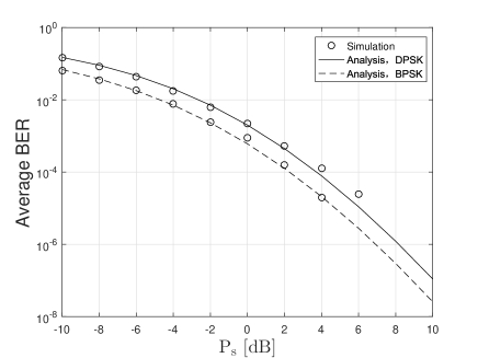
where different values of and correspond to various modulation schemes. For instance, differential phase shift keying (DPSK) ( and ), binary phase shift keying (BPSK) ( and ), and binary frequency shift keying (BFSK) ( and ). In this work, we consider the DPSK and the BPSK schemes.
From (6) and (11), and using [15, Eq.(07.34.21.0088.01)], the average BER can be evaluated as
| (12) |
III-C Average Channel Capacity
From [16], we have
| (13) |
For a simple calculation of the capacity, one can apply a useful identity in [15, Eq.(01.04.26.0003.01)], i.e., . By combining [15, Eq.(07.34.21.0011.01)] together with (5) and (13), the average capacity can be evaluated as
| (14) |
IV Numerical Results and Discussions
In this section, we select some numerical examples to verify the impact of the main system parameters on the system performance. Our analysis is confirmed by Monte Carlo simulations, which generates simulation points. In the next figures, the SIR threshold is set to .
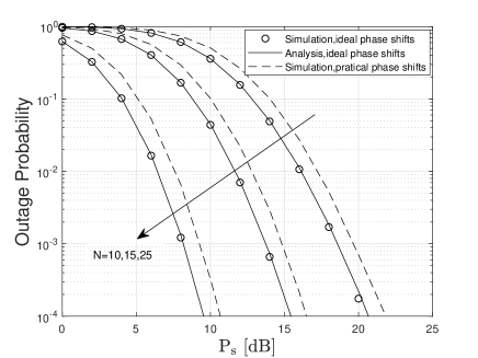
In Fig. 2, we present the OP performance of our considered system with various values of , and by setting the number of interferers , with all interferers having the same power, i.e., . From this figure, one can find that the analytical results match the simulation results perfectly. In addition, the simulation results of the ideal and practical phase shifts are given to observe the performance hit. As mentioned in [3], one can use to represent the performance loss when considering the practical phase shifts, where stands for the minimum amplitude, represents the horizontal distance between and , and denotes the steepness of function curve. We consider the setup , , and . One can clearly see that there is a certain performance difference between the practical and ideal cases. Finally, it can be observed that applying large values of can result in a better system performance.
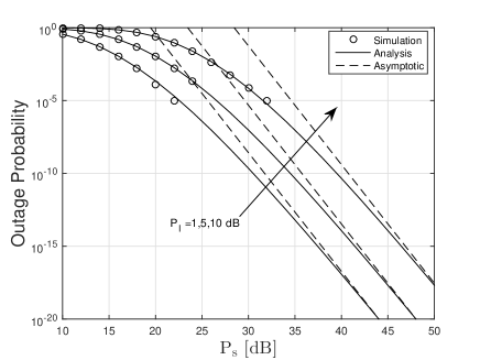
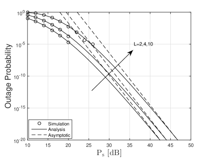
In Fig. 3, we plot the OP curves for various values of and by setting and . As can be seen, increasing leads to a deterioration of the OP performance. In Fig. 4, the OP is plotted for various values of and assuming and . The results show that increasing the amount of interference reduces the system performance. From both Figs. 3 and 4, one can be clearly seen that all curves have the same slopes, which means that the existence of interference does not affect the diversity order of the considered system, corroborating the fact that the diversity order depends on . Also, at high , the asymptotic results are close to the exact values.
In Fig. 5, we plot the BER curves for both DPSK and BPSK schemes when , and . One can clearly observe that the BPSK scheme has a better system performance.
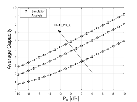
Finally, Fig. 6 depicts the average capacity of our considered system for various values of and assuming and . Again, it can be clearly seen that the analytical results match perfectly the simulation ones. Moreover, the system performance improves as increases.
V Conclusion
In this paper, we presented a performance analysis for RIS-assisted communication systems with equal power CCI. We first performed an accurate analysis of the OP, average BER, and average capacity. The results showed that our analysis results match the simulation ones perfectly. In order to clearly study the effect of parameters on the system performance, we derived an asymptotically closed-expression for the OP. The results revealed that the achievable diversity order equals to , and the number of interferers has a great influence on the system performance.
References
- [1] E. Basar, M. Di Renzo, J. De Rosny, M. Debbah, M. S. Alouini and R. Zhang, “Wireless communications through reconfigurable intelligent surfaces,” IEEE Access, vol. 7, pp. 116753-116773, Aug. 2019.
- [2] X. Hu, J. Wang, and C. Zhong, “Statistical CSI based design for intelligent reflecting surface assisted MISO systems,” Sci. China: Inf. Sci., Aug. 2020.
- [3] S. Abeywickrama, R. Zhang, Q. Wu and C. Yuen, “Intelligent reflecting surface: practical phase shift model and beamforming optimization,” IEEE Trans. Commun., Early Access, DOI: 10.1109/TCOMM.2020.3001125.
- [4] C. Huang, A. Zappone, G. C. Alexandropoulos, M. Debbah and C. Yuen, “Reconfigurable intelligent surfaces for energy efficiency in wireless communication,” IEEE Trans. Wireless Commun., vol. 18, no. 8, pp. 4157-4170, Aug. 2019.
- [5] L. Yang, Y. Yang, M. O. Hasna, and M. Alouini, “Coverage, probability of SNR gain, and DOR analysis of RIS-aided communication systems,” IEEE Wireless Commun. Lett., vol. 9, no. 8, pp. 1268-1272, Aug. 2020.
- [6] L. Yang, J. Yang, W. Xie, M. O. Hasna, T. Tsiftsis, M. Di Renzo, “Secrecy performance analysis of RIS-aided wireless communication systems,” IEEE Trans. Veh. Technol., Early Access, DOI:10.1109/TVT.2020.3007521.
- [7] L. Yang, W. Guo, and I. S. Ansari, “Mixed dual-hop FSO-RF communication systems through reconfigurable intelligent surface,” IEEE Commun. Lett., vol. 24, no. 7, pp. 1558-1562, Jul. 2020.
- [8] L. Yang, F. Meng, J. Zhang, M. O. Hasna, and M. Di Renzo, “On the performance of RIS-assisted dual-hop UAV communication systems,” IEEE Trans. Veh. Technol., Early Access, DOI:10.1109/TVT.2020.3004598.
- [9] L. Yang, F. Meng, Q. Wu, D. B. da Costa and M. Alouini, “Accurate closed-form approximations to channel distributions of RIS- aided wireless systems,” IEEE Wireless Commun. Lett., Early Access, DOI:10.1109/LWC.2020.3010512.
- [10] I. S. Gradshteyn, and I. M. Ryzhik, Table of integrals, series, and products, 7th ed. San Diego, CA, USA: Academic, 2007.
- [11] L. Yang, K. Qaraqe, E. Serpedin and M. Alouini, “Performance analysis of amplify-and-forward two-way relaying with co-channel interference and channel estimation error,” IEEE Trans. Commun., vol. 61, no. 6, pp. 2221-2231, Jun. 2013.
- [12] M. K. Simon and M.S. Alouini, Digital communication over fading channels: A unified approach to performance analysis, 1st Edition. John Wiley, 2000.
- [13] Z. Wang and G. B. Giannakis, “A simple and general parameterization quantifying performance in fading channels,” IEEE Trans. Commun., vol. 51, no. 8, pp. 1389-1398, Aug. 2003.
- [14] I. S. Ansari, S. Al-Ahmadi, F. Yilmaz, M. Alouini, and H. Yanikomeroglu, “A new formula for the BER of binary modulations with dual-branch selection over generalized- composite fading channels,” IEEE Trans. Commun., vol. 59, no. 10, pp. 2654-2658, Oct. 2011.
- [15] (2001). Wolfram, Champaign, IL, USA. “The wolfram functions site,” [Online]. Available: http://functions.wolfram.com.
- [16] J. Vellakudiyan, I. S. Ansari, V. Palliyembil, P. Muthuchidambaranathan, and K. A. Qaraqe, “Channel capacity analysis of a mixed dual-hop radio- frequency-free space optical transmission system with mlaga distribu- tion,” IET Commun., vol. 10, no. 16, pp. 2119-2124, Oct. 2016.