The NederDrone: a hybrid lift, hybrid energy
hydrogen UAV
Abstract
A lot of UAV applications require vertical take-off and landing (VTOL) combined with very long-range or endurance. Transitioning UAVs have been proposed to combine the VTOL capabilities of helicopters with the efficient long-range flight properties of fixed-wing aircraft. But energy is still a bottleneck for many electric long endurance applications. While solar power technology and battery technology have improved a lot, in rougher conditions they still respectively lack the power or total amount of energy required for many real-world situations. In this paper, we introduce the NederDrone, a hybrid lift, hybrid energy hydrogen-powered UAV which is able to perform vertical take-off and landings using 12 propellers while flying efficiently in forward flight thanks to its fixed wings. The energy is supplied from a mix of hydrogen-driven fuel-cells to store large amounts of energy and battery power for high power situations. The hydrogen is stored in a pressurized cylinder around which the UAV is optimized. This paper analyses the selection of the concept, the implemented safety elements, the electronics and flight control and shows flight data including a 3h38 flight at sea, starting and landing on a small moving ship.
keywords:
PEM fuel-cell , Hydrogen , Pressure cylinder , Tail-sitter , Hybrid UAV , Maritime UAV1 Introduction
- CAN
- Controller Area Network
- CNG
- Compressed Natural Gas
- CTS
- Composite Technical Systems
- ESC
- Electronic Speed Controller
- EPP
- Expanded Polypropylene
- INDI
- Incremental Nonlinear Dynamic Inversion
- LHV
- Lower Heating Value
- OJF
- Open Jet Facility
- PCP
- Pre-Charged Pneumatic
- PEM
- Polymer Electrolyte Membrane
- PET
- Polyethylene Terephthalate
- TPED
- Transportable Pressure Equipment Directive
- UAV
- Unmanned Air Vehicles
- VTOL
- Vertical Take-Off and Landing
Unmanned Air Vehicles (UAV) offer solutions in a large variety of applications [1]. While a lot of applications can be performed with current battery technology, for many others the energy requirements cannot be met [2]. In particular when combined with the requirement to have Vertical Take-Off and Landing (VTOL) capabilities, the traditional efficient fixed-wing aircraft is not an option. This is where a lot of hybrid concepts, namely combinations of efficient fixed-wings and hovering rotorcraft, have been proposed in recent years.
1.1 Hybrid Lift
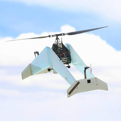
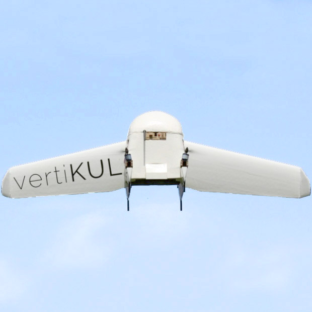
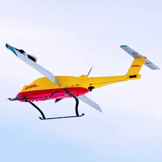
The most common categories of hybrid lift UAV are the tail-sitters, dual-systems and transforming UAV [6]. Tail-sitters pitch down during the transition from hover to forward flight, and while they have important draw-backs for pilot comfort [7], they have gained a lot of new interest for UAV. They are mechanically simple yet allow to re-use propulsion systems in several phases of the flight [4]. Many different types of tail-sitters exist. They can either be optimized to maximize the hovering efficiency with a single large rotor [3] (See Fig.1(a)) or to minimize complexity [8]. Other tail-sitters were optimized for maximal redundancy [9] or were given re-configurable wings to minimize sensitivity to gusts in hover [10].
1.2 Hydrogen UAV
But despite large advancements in battery technology and drone technology, energy storage has remained the biggest bottleneck for the endurance of UAV. Recent advancement in lightweight robust fuel-cell technology has increased the interest of using them in UAV applications [13].
Fuel-cells for UAV have been proposed for a long time [14]. But a lot of problems had to be overcome before getting small reliable membranes which can power more than just the most efficient UAV [15]. In several UAVs the fuel-cell power had to be complemented with for instance lithium-ion batteries [16]. In the last decade, hydrogen fuel-cell powered quadrotors have been developed [17], which show the viability of the concept. But flight times of hydrogen powered multi-copters never reach the endurance seen in fixed-wings.
Many fixed wing hydrogen UAVs have been proposed like the demonstrator from [18] in 2007, the UAV from [17] in 2012, the from [19] in 2017 to the 2020 [20]. Other projects investigated the combination of hydrogen power with solar power [21], which effectively helped to double their flight time in ideal conditions. This combination has also been proposed to cross the Atlantic [22]. But in most projects, a combination of battery power for high demand situations and hydrogen power for endurance has been used, which is referred to as hybrid energy [23].
1.3 Hybrid Lift Hybrid Energy
To combine the advantages of hybrid lift UAV with those of hybrid energy from batteries and hydrogen fuel-cells, a new concept is developed. Section 2 investigates the selected type of fuel-cell and safety aspects of flying with hydrogen. Section 3 explains the design choices of the hybrid UAV built around the fuel-cell system. Section 4 explains the hybrid power wiring and dual control bus of the NederDrone. Section 6 describes the essential aerodynamic properties. Section 5 explains the control. Section 7 shows actual test flight data. Finally Section 8 and 9 give a discussion and conclusion respectively.
2 Hydrogen powered electric flight
Hydrogen powered fuel-cells form an attractive solution for sustainable aircraft if the remaining technological problems can be solved [24]. The main elements consist of a fuel-cell and backup power which are sufficient for the drone, a hydrogen storage solution and important safety considerations.
2.1 Fuel-cell
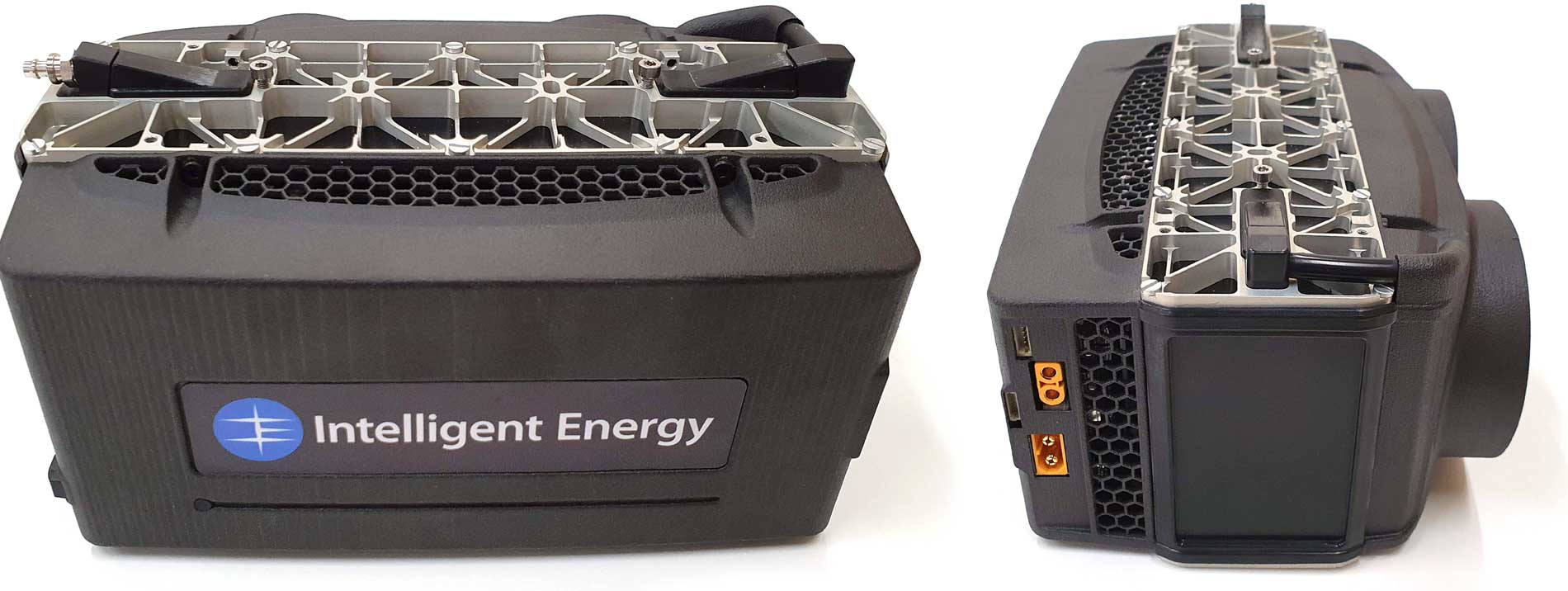
The three most common fuel-cells used to power UAVs are: 1) Polymer Electrolyte Membrane (PEM) fuel-cells, 2) direct methanol fuel-cells, and 3) solid oxide fuel cells [25]. But the availability of ready to use systems at the time of selection also plays an important role. Although PEM fuel-cell efficiency drops with altitude [26], and their membrane must be re-humidified to unlock their full power when not used for a few days [27], they form an attractive choice for UAV. Two options within the power range from to were available, namely PEM fuel-cell systems from Intelligent Energy222http://www.intelligent-energy.com (IE) and HES Energy Systems333https://www.hes.sg/ (HES).
| Lipo | ||||||
|---|---|---|---|---|---|---|
| Unit | [W] | [W] | [cell] | [%] | [kg] | [kg] |
| HES | 250 | 250 | 6 | 50% | 0.73 | 0.14 |
| 500 | 500 | 7 | 52% | 1.4 | 0.14 | |
| IE | 650 | 1000 | 6 | 56% | 0.81 | 0.14 |
| 800 | 1400 | 6 | 55% | 0.96 | 0.14 |
The IE air-cooled PEM fuel-cell running at ambient temperatures was selected (See Fig.2), which is packaged as a small light-weight cost effective and robust system. It runs at the easily available 6-cell lithium output voltage and—at the time of selection—had a better hydrogen efficiency and weight efficiency.
The Lower Heating Value (LHV) efficiency of the system is between at and at 444IE: uploads/product_docs/61126_IE_-_Cylinder_Guide_May_2020.pdf. The fuel consumption in at predicted forward flight conditions of average power use then becomes:
| (1) |
A hydrogen LHV of is used in further computations. This results in a fuel consumption (1) of not more than at average power and up to at full power. To fly at least at maximum fuel-cell power—to also deliver payload power and be able to climb descend, hover and recharge hover batteries in-flight—about of hydrogen would be desired.
The corresponding Intelligent Energy Transportable Pressure Equipment Directive (TPED) regulator is , 40 by 35mm (diameter x length), 20 to ‘in’ and ‘out’ and is equipped with an electronic shut-off valve, pressure sensors and a standard Pre-Charged Pneumatic (PCP) fill port. The fuel-cell system weighs and measures 196 by 100 by . It’s output voltage ranges from to . It is equipped with a 6-cell lithium-polymer auxiliary battery of which enables the combined system to deliver of peak power for a short time.
2.2 Solid versus Pressure Cylinder


At room temperature, the main two options to store hydrogen are to store it as a pressurized gas in a pressure cylinder, or to store it as a chemical solution that releases hydrogen [28]. Sodium borohydride () has been proposed as hydrogen source to power fuel-cells [29, 30].
The downside of pressure cylinders is that they weigh orders of magnitude more than the hydrogen inside them [31]. But because of sustainability, overal system weight, off-grid recharge options [32], price, and availability, the choice was made to use pressure cylinders.
The mass of hydrogen based on the cylinder volume and pressure in flight conditions is fitted as555https://h2tools.org/hyarc/hydrogen-data/hydrogen-density-different-temperatures-and-pressures:
| (2) |
It should be noted that the actual value varies with temperature. At , values change from at to at (Fig.3(a)) and a drop in temperature leads to a increase in hydrogen. In this paper the more pessimistic values at room temperature are used. Table 2 shows an overview of available cylinder options. The same data is shown in Fig.3(b). This shows that at time of selection, the lightest cylinders are the HES A-Series and F-Series.
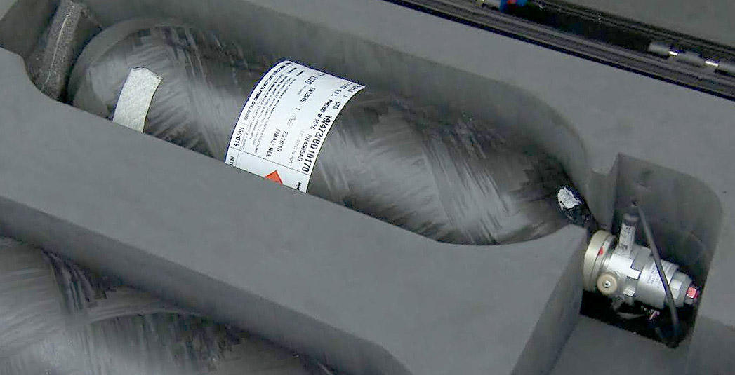
Unfortunately, due to price, availability and EU certificates, this option was not yet available. The selected cylinder is the Composite Technical Systems (CTS) Polyethylene Terephthalate (PET) Liner Type-4 cylinder666http://www.ctscyl.com/prodotti/h2/cts-ultralight-6-8l-300-bar-h2. The graph does however illustrate that doubled weight densities can be expected soon. A picture of the actual cylinder can be found in Fig.4.
2.3 Hydrogen and Safety
At , hydrogen gas weighs about . It is flammable in concentrations from up to when mixed with air and burns optimally at a concentration of . It has a self-ignition temperature , but a very low required ignition energy of , while human body models show that a person without static protection can easily cause a discharge. To avoid ignition, anti-static shoes and clothes are required when leakages are expected—like for instance during filling. Refueling should be done at temperatures in between and to stay within tank limitations. Hydrogen is roughly 14 times lighter than air and therefore easily gets trapped inside rooms. The area where hydrogen is used should be well ventilated as per ATEX 153 and for ignition analysis one should refer to EN1127-1. At room temperatures, hydrogen is nearly completely converted to orhto-hydrogen, and no significant heating effect is to be expected when depressurizing it. When assembling a UAV, applicable regulations include the EU 94/9/EC (ATEX 114) and ISO 15196 for material properties and their degradation in the presence of hydrogen [33].
2.4 Cylinder Safety
A lot of work has already been preformed in the field of pressure tank rupture analysis but most has been done on metal cylinders used for a variety of gasses like Compressed Natural Gas (CNG) [34]. For composite high pressure cylinders, models and methods have been developed and validated [35], but these do not show all risks of hydrogen cylinder failures.
Actual crush test of composite hydrogen cylinders have been performed by [36] to simulate a car crash. But they used mainly cylinders with aluminum insides (type 3A/B). The blast of hydrogen cylinders exposed to vehicle fires was also investigated [37]. They suggest that the blast from a cylinder failure through fire (with combustion) can throw debris up to , but also shows that would be a no-harm distance for the shock-wave of a cylinder, which is much larger than the UAV cylinder.
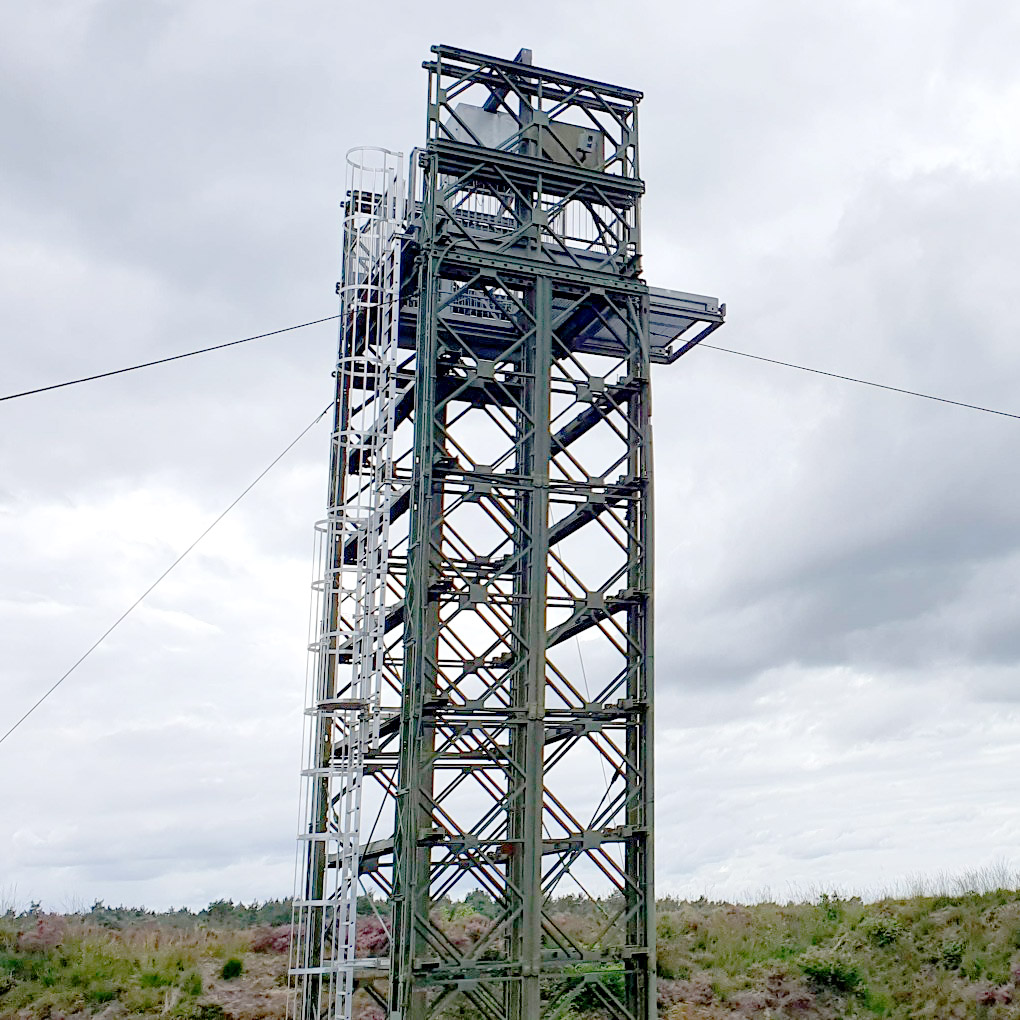
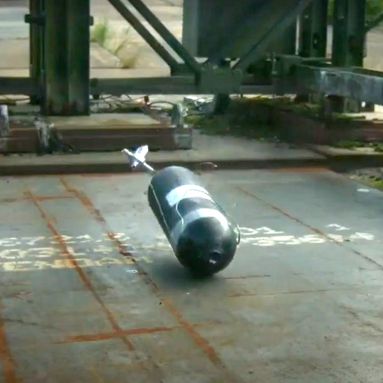
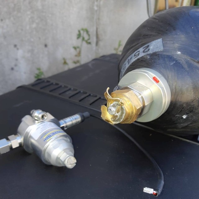
The selected cylinder was tested by the manufacturer according to the NEN-EN12245+A1. Since no data was available about the safety of the combined cylinder and pressure regulator, a drop test was organized that simulated the fall on the metal deck of a ship. While this does not represent the worst-case scenario of a crash involving hydrogen, it does address the operational scenario in which the hydrogen drone moves away from the ship as soon as possible after take-off and only moves over the ship at low speed and low altitude upon landings. The test was performed according to the STANAG 4375. The cylinder was dropped from a high tower (Fig.5(a)) on a metal plate on concrete (Fig.5(b)) while filled with or about of hydrogen. High-speed camera footage was made and the post impact damage was assessed. The metal regulator broke (Fig.5(c)), which resulted in a leak. After a few minutes all hydrogen had escaped and the cylinder was inert.
3 Hybrid lift concept
Fitting a hydrogen cylinder and fuel-cell in a hybrid UAV poses specific constraints [14, 23, 17]. The large and bulky cylinder highly influences the aerodynamic shape. To cool the fuel-cell and remove the formed water vapour, sufficient airflow through the fuel-cell radiator is important. The relatively large weight of the energy supply and payload combined with the weight of the propulsion needed to hover, poses strict limitations on structural weight. And flying with pressure cylinders and expensive equipment poses stricter redundancy constraints. This section will go through these challenges.
3.1 Trade-off

First a trade off is made between the three main classes of hybrid lift UAVs. The dual-system VTOL UAV like quad-planes have a separate propulsion system for hover and forward flight (Fig.6a). To minimize weight, a minimalist hover system is often used as this is dummy weight during the largest part of the flight. The hover propulsion blows perpendicularly to the wing, and thereby needs additional arms to support the motors at a distance from the wing, which also adds weight and drag in forward flight. The tilt wing (or tilt-motor) concept (Fig.6b) has a mechanism to rotate the entire wing, hereby removing the need for separate motor support arms and re-using part of the propulsion from hover in forward flight. The downside is increased mechanical complexity, higher mechanical weight and the control complexity of flying with a changing morphology. A tail-sitter option—shown in Fig.6c—re-uses the same motors while keeping mechanical simplicity. The propulsion can be attached to the wing, which reduces overall structural weight. As the vast majority of the flight is typically in forward flight, the propulsion can be optimized towards this phase. The drawbacks are that the UAV must pitch down during the transition and hereby passes through the stall regime of the wing. Moreover, the cylinder is vertical after landing which makes it prone to tipping over especially on moving platforms like ships.
To minimize structural weight and complexity, while maximally re-using the hover propulsion in forward flight, the tail-sitter concept was selected for the NederDrone.
3.2 Forward flight drag minimization

Three variables form a trade-off for the orientation of the cylinder: drag, ground stability and control authority in hover. The best control authority in hover is achieved by maximizing the distance between the motor center-lines (Fig.7b). Hereby, higher control moments can be created through differences in thrust. After landing the cylinder lies flat and stable on the ground. But this configuration has the highest fuselage drag in forward flight as the frontal surface is increased. Moreover, the wings are then placed on top of each other, which cannot result in an aerodynamically stable aircraft in forward flight without S-shaped airfoil or significant wing sweep angle.
Previous work [9] made a compromise and placed the cylinder at a negative angle with the incoming flow (Fig.7c). The presumed advantages during the landing phase to slowly roll down were found to be insufficient and a landing gear was still needed to protect the propellers. Moreover the design goal of staying below in forward flight could not be achieved. Therefore the cylinder was placed completely inline with the flow as in Fig.7a. This helps to also increase the maximal forward flight speed.
3.3 Longitudinal stability
To minimize drag, the cylinder and the fuel-cell are all placed in-line. This makes the longitudinal distribution of mass in the length of the fuselage significant. To improve the damping of the short period pitch motion in forward flight, either a large elevator or a long fuselage is desired [38]. This conflicts with the ground stability requirement after landing as a long narrow tail-sitter is at high risk of tipping over and the center of gravity falls from higher in case it does.
The combined requirements are addressed by giving the NederDrone a short fuselage and a tandem wing configuration. The tandem wing has the best pitch damping for a given fuselage length. Moreover, it has a shorter wingspan for a given amount of wing area at a given aspect ratio compared to a conventional large main wing and a small horizontal stabilizer. These shorter wings help to cope with higher perturbations in hover.
3.4 Ground stability
An important property is the stability of the vehicle after landing. Having a long narrow UAV upright containing a high pressure carbon cylinder on a moving platform like a ship after landing is not a stable option.
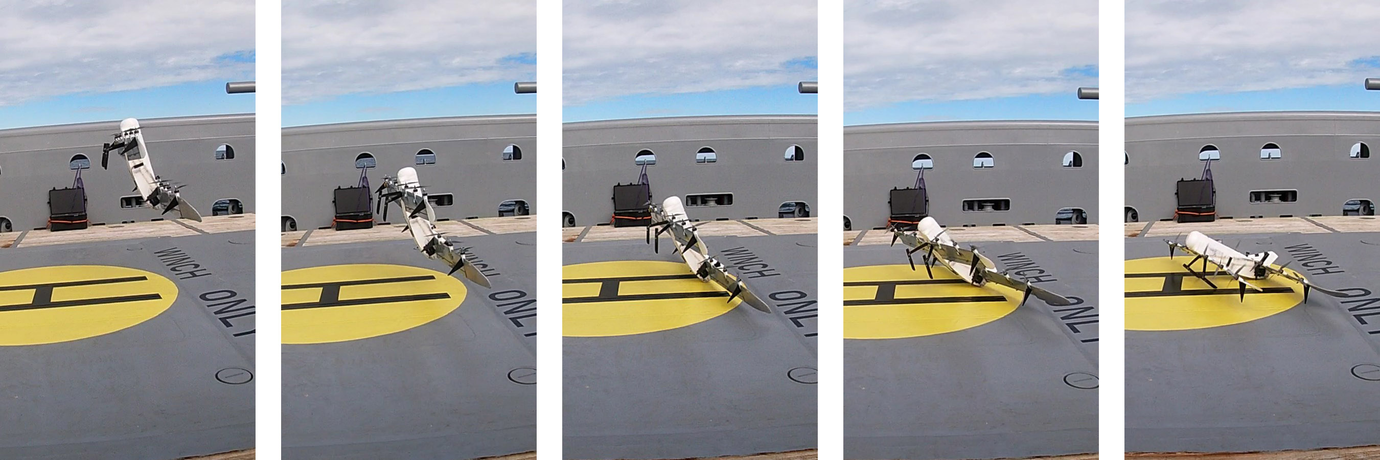
Inspired by [9] illustrated in Fig.7c, the option was investigated to slowly drop-down the nose after landing. Using the hover propellers, the nose is slowly dropped with the motors on the back wing at minimal thrust. Once the remaining hover propellers start to point forward beyond a measured angle, the ground friction is overcome and the drone would start to slide forward. At this point the thrust is cut off and the nose drops down. To allow this, a sprung landing gear was added which could absorb the last part of the drop. The result is a UAV which lies stably on the ground after landing.
To further minimize the impact of the landing, the center of gravity was moved backwards by choosing a canard configuration with the largest wing at the back. This places the center of gravity much closer to the ground while in hover. The resulting landing sequence is shown in Fig.9.
3.5 Take-Off
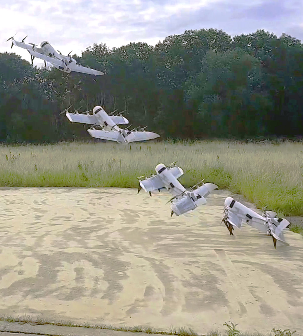
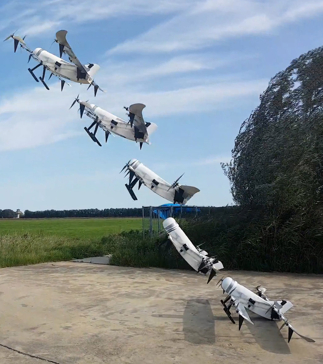
The ground stability requirement is conflicting with the vertical take-off requirement of the tail-sitter. Since the UAV is sitting in a nose down from hover, this affects the vertical take-off. However, test flights showed that even in worst-case ‘no-wind’ conditions the UAV only slides less than a foot before taking off as shown in composite image Fig.10. The high thrust to weight, the ground effect of the propeller flow over the wing squeezed between the wing and the ground and the spring in the landing gear make the NederDrone take-off on the spot into what will be referred to as an angled take-off.
4 Electronics
4.1 Power: concept
Hovering a platform in gusts while the propulsion is optimized for the much longer forward flight phase is taking more than the maximum of the fuel-cell system. To complement the fuel-cell during the short high power phases, high C-rating lithium polymer batteries are added to the NederDrone. The fuel-cell provides a nominal output voltage of , which drops when the load increases. Six cell lithium-polymer batteries recommendation state that they can safely be charged up to , which matches perfectly with the fuel-cell voltage range including a safety margin of to prevent over-charge. To minimize weight, the batteries are connected directly to the motors in parallel to the fuel-cell. But to prevent that the hover batteries would feed current into the fuel-cell, the fuel-cell current is run through a set of small diodes at each motor. This allows the very high currents to go form the lithium battery directly to the Electronic Speed Controller (ESC) without loss and allows the fuel-cell to re-charge the batteries to no more than minus the diode forward drop voltage of about . This means the lithium-polymer batteries are charged up to about which corresponds to at least full. The power and control wiring is depicted in Fig.11.

The selected hover battery consists of four Extron X2 6S 1P lithium-polymer batteries with a nominal voltage of and a discharge rate of 25C to 50C. They contain just under of additional energy at each and can supply continuous and burst currents. The four batteries are placed as near as possible to the four wings to supply the 3 motors on each with short high power wires. These 4 extra batteries combined provide sufficient current for the most demanding conditions and provide enough energy to fly for at least in case the fuel-cell fails in-flight.
4.2 Control bus: Aerospace CAN
For redundancy and structural weight distribution purposes the NederDrone has twelve motors. To reduce wiring and connector failures and create a system which is still able to fly even if any of the wires would fail, the power and control wires are duplicated. This would lead to 24 control wires going to the 12 motors, excluding the motor status feedback wires and dual power bus. To reduce this large amount of wiring and weight, a control network is used (See Fig.11).
The Controller Area Network (CAN) is an automotive industry technology that has been proposed as a low cost solution in several aerospace applications [39]. The increasingly popular [40] UAVCAN777https://uavcan.org/ implementation was selected with custom messages. The resulting system is a setup where any control or power wire can be cut without dramatic consequences, while the weight and complexity is kept to a minimum.
5 Control
In selecting a controller for the NederDrone, its special challenges were considered. First, though the NederDrone does not ‘sit on its tail’ when landed, in terms of flight mechanics it does behave like a tail-sitter. The control of tail-sitters is complicated by the wings that operate at large angles of attack during slow flight. This makes it difficult to model the lift, drag and pitching moment accurately. It can also lead to sudden changes in the aerodynamic forces and moments when the flow over the wings suddenly stalls or re-attaches. Tail-sitters are typically susceptible to wind gusts, due the large exposed surface during hovering flight. These disturbances need to be compensated by the controller. Second, the design of the NederDrone is somewhat unorthodox with its tandem-wing configuration, and the slipstream from the front wing can hit the back wing. This is expected to produce a complex interaction at certain angles of attack (consider Fig.8 and imagine a horizontal velocity to the right), which would be hard to predict. Third, the experimental nature of the project required a control method that could be easily adapted to changes made to the platform, without needing new wind tunnel tests.
To cope with these challenges, Incremental Nonlinear Dynamic Inversion (INDI) was proposed as the method of control, because of its successful implementation on the Cyclone tail-sitter UAV, which had similar challenges [8].
5.1 Cascaded INDI Control
INDI is a control method that makes use of feedback of linear and angular acceleration to replace much of the modeling needs, since these signals provide direct information on the forces and moments that act on the vehicle [41]. The angular acceleration can be obtained through differentiation of the gyroscope signal, and the linear acceleration is directly measured with the accelerometer. Based on the difference between desired and measured linear and angular acceleration, control increments are calculated using the control effectiveness. Because disturbances are directly measured with the accelerometer and the gyroscope, they can be counteracted very effectively. The disturbance rejection properties of INDI have been shown theoretically and experimentally in previous research [42].
The general structure of the controller is given in Fig.12, in which is the position, is the attitude, and the angular rate of the vehicle. The control moments are denoted by , and , the total thrust is , and the commands to the servos and motors is . Signals that are filtered with a low pass filter have a subscript . From this figure the cascaded structure becomes clear, with an inner and an outer INDI loop.
5.2 Structural Modes

During the test flights, it was found that the frequency of some of the structural modes—in particular the longitudinal torsion mode—was relatively low. To avoid interaction between the controller and the structural modes, the common procedure in aerospace is to make sure that the controller has a sufficiently small open loop gain at the structural resonance frequency [43]. This can be achieved by including a low pass or a notch filter on the relevant feedback signals. For the INDI inner loop, there is already a low pass filter, since the angular acceleration signal is typically noisy due to high frequency vibrations coming from the motors. Though including a separate notch filter to dampen the structural mode could result in an overall lower phase lag, this also requires knowledge of the frequency of the structural mode. To keep the design simple, the cutoff frequency of the second order Butterworth low pass filter that was already in place was set to for the pitch rate and yaw rate, and to for the yaw rate and linear acceleration. It should be noted that these filter cutoff frequencies are relatively low, and lead to reduced disturbance rejection performance.
Nevertheless, to illustrate the ability of INDI to handle large disturbances, Fig.12 shows a NederDrone take-off with one tip propeller turning in reverse direction—thus pushing backwards instead of forwards. The INDI stabilizes the NederDrone within seconds although requiring a roll command to compensate.
6 Aerodynamics
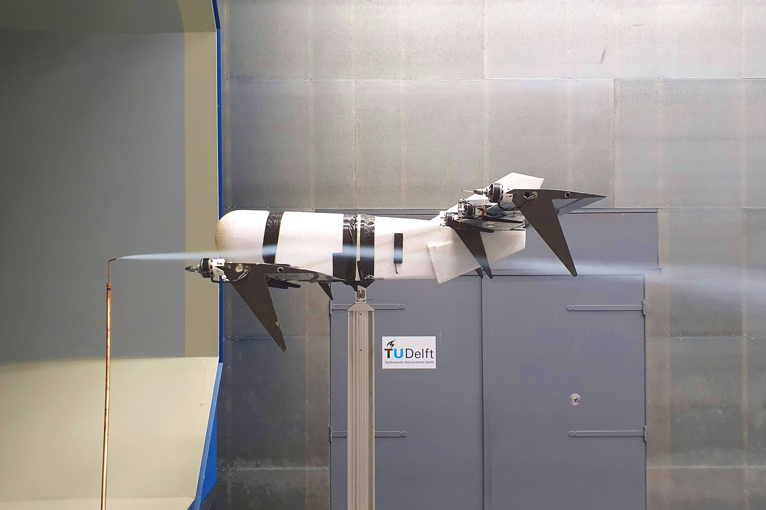

The airfoil for the wings has been chosen for a good compromise between ‘gentle stall’ and ‘low drag throughout the lift curve’ using the XFoil module within XFLR5888http://www.xflr5.tech/. It is based on a MH32 airfoil, but was modified to allow construction from Expanded Polypropylene (EPP). Wind-tunnel measurements were performed in the TUDelft Open Jet Facility (OJF) [44], in which the full scale NederDrone can be tested (See Fig.14). The gentle stall was confirmed and is shown in Fig.15.
7 Results


The concept was built and tested in real flight. The wings are made of EPP cut with hot-wire and strengthened with dual carbon spars. Carbon ribs connect the spars to the motor mounts. Various parts like the motor mounts were built with the increasingly popular and powerful 3D printing technology [45]. To withstand the motor heat, the motor mounts were printed from high temperature resistant Ultimaker CPE+ filament. The autopilot software is the Paparazzi-UAV autopilot [46, 47] project, which has support for various key features like low-level CAN drivers to INDI control implementations for hybrid aircraft, together with the ability to easily create custom modules to interface with the fuel-cell systems. The autopilot hardware is the Pixhawk PX4 MBS-ENTB-24 board. The used motors are 12 T-Motor MN3510-25-360 motors equipped with APC 13x10 propellers. Servos are the waterproof HS-5086WP metal gear, micro digital waterproof servos. Telemetry is exchanged via the HereLink system.
7.1 Battery-only flight testing
Before flying with hydrogen, a mock-up hydrogen system was 3D printed and filled with batteries and metal to achieve the exact component weight. The mock-up cylinder was equipped with a 6S6P lithium-ion battery (NCR18650GA) to simulate the power delivered from the fuel-cell. This allowed to safely fly over . A sample flight is shown in Fig.16 in which the pitch angle on the ground, take-off, hover, transition, forward flight and forward turns can be seen. Once the NederDrone with mock-up hydrogen components had flown dozens of flight hours successfully including many test flight from a ship, it was equipped with the hydrogen systems.
7.2 The first ever hybrid lift hybrid energy hydrogen flight at sea
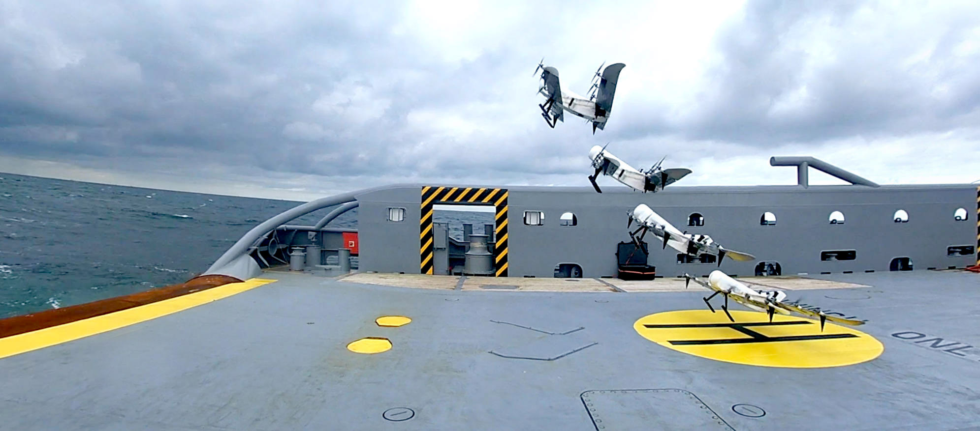
To demonstrate the capabilities of the NederDrone we performed a test flight at sea in real world conditions. On September 30th 2020, the NederDrone with fuel cell took off from a sailing coast guard ship in moderate wind conditions with 20 knots of wind. The flight lasted 3 hour and 38 minutes. A composite image of the take-off is shown in Fig.17.
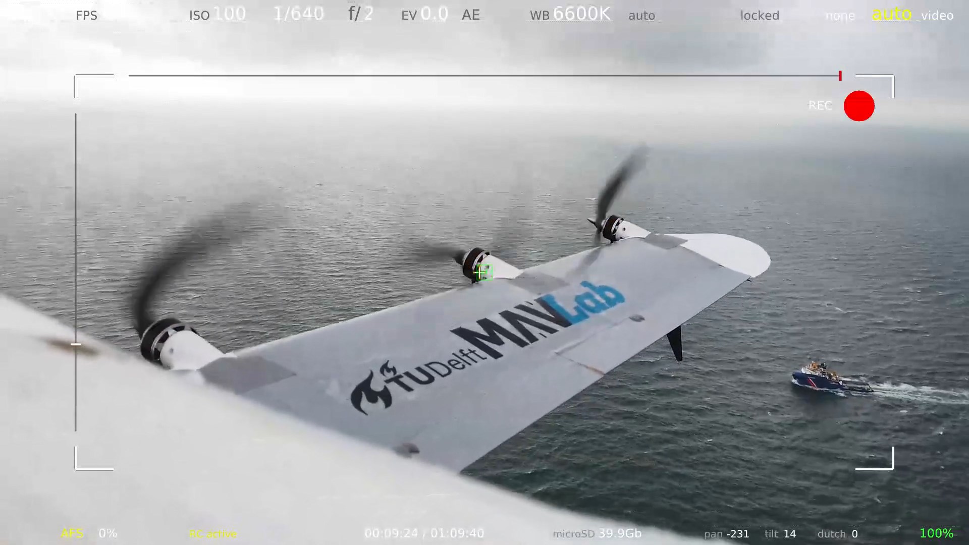
The onboard video of the pan-tilt HD camera protruding from the top of the NederDrone was streamed via the 2.4GHz ISM-band HereLink data-link. A live video view of the NederDrone following the ship is shown in Fig.18. All battery powered data-links and video systems were also charging from the hydrogen energy and stayed fully charged during the entire flight.
After landing, the empty cylinder can be replaced with a new full cylinder in seconds, before taking off again. The presented test flight does not push endurance to its limits. There was at least 20 minutes worth of hydrogen and 15 minutes of battery left after landing. All systems were running at full power and the weather was rough with 5 Beaufort (20kt) wind and moderate turbulence. The propellers used during this flight were optimized for fast flight and not for maximum endurance. This illustrates that the hybrid lift hybrid power UAV called NederDrone is built for real world operations and has considerable safety, performance and energy margins.
7.3 Energy profile of the 3h flight


The hydrogen cylinder was filled with a pressure of after settling at ambient temperature. Fig.19 shows the depletion of the hydrogen cylinder as measured by the onboard sensors. It follows the inverse of the density profile from (2). Having reached the desired 3 flight hours, the flight was stopped at a remaining pressure of , although previous tests proved that the NederDrone can continue to fly safely on battery power after complete depletion of the cylinder and shutdown of the fuel-cell.
During take-off and landing, lithium batteries provide the required extra power while the fuel-cell is running at maximum power. Fig.20 shows the reported power used by the ESCs. This excludes the power used by the fuel-cell itself and its cooling, power losses in the long wires, power loss over the diode, and power used by the payload and video link. The descend power becomes nearly zero at moments when the NederDrone is gliding in forward flight with the propellers windmilling. The climb power (from 20 to ) is about during the angled take-off with the wings not stalled and thus significantly helping in lift production. The hover power required in the last phase of the landing while fighting turbulence with the wing stalled () consumed nearly with peaks of over . This is much more than the raw fuel-cell system can handle but is supplied from the high current rated lithium hover batteries with ease. Fig.21 shows that the power delivered by the fuel-cell in those cases is about as by design. Two minutes after the take-off, the NederDrone transitions to forward flight and starts using much less power. The sum of the flight power, payload power and fuel-cell systems (including cooling) power are an average of . After the take-off the fuel-cell slowly re-charges the lithium batteries that were used during take-off. This means the hovering lithium batteries are fully charged before landing.
8 Discussion
Hydrogen is seen as a highly promising future fuel for aviation thanks to its high power density. But the limited power that can be generated by fuel-cells limits the applicability. Furthermore, the onboard storage of pure hydrogen requires a pressure cylinder with a weight that is easily one quarter of the vehicle weight and has shape constraints.
To allow the successful application of hydrogen in UAVs, it is important that the vehicle does not have severe operational limitations and it is primordial that the safety is guaranteed. This underlines the importance to find concepts that do not need very long runways but nevertheless fly fast and efficiently. At the same time these platforms must be very safe as the consequences of accidents with onboard pressure cylinders filled with hydrogen can be significant. This requires platforms with redundant flight modes, redundant energy and redundant control. The shape of the UAV can also play a big role in the protection of the cylinder. Light foam around the cylinder provides both an aerodynamic shape and a large crumble zone for a low weight. By placing the sensitive high-pressure regulators backwards in the middle of the vehicle, safety can be further increased. Last but not least, by having dual flight modes, an additional recovery mode is created in case of failure. When for instance aerodynamic actuators would fail, then the platform can return and land in hovering flight. If on the other hand many motor controllers would fail, then the platform can still be flown in forward flight by exploiting the efficiency of its fixed-wings. This combined versatility and safety is expected to play an important role in the development of hydrogen fuelled flight.
9 Conclusions
A novel hydrogen UAV was presented called the NederDrone 999http://www.nederdrone.nl/. It is a tail-sitter hybrid lift vehicle with tandem wings for forward flight, and 12 propellers for hover. The power comes from a PEM fuel-cell with hydrogen stored in a pressurized cylinder around which the UAV is optimized. The dual automotive CAN control bus, redundant power source, wiring, propulsion, dual flight modes and model-less INDI control make the NederDrone particularly resilient to failures. The versatility and flight endurance of the NederDrone is shown with a 3h38 test flight at sea from a moving ship with winds.
Acknowledgements
The developments presented in this work would not have been possible without the support from the Royal Netherlands Navy and the Netherlands Coastguard.
Appendix A Cylinder Overview
An overview of the considered pressurized hydrogen cylinders is given in Table 2.
| H2 | [Wh | WT% | |||||||
| [L] | [bar] | [Wh] | [kg] | [g] | /kg] | H2 | [mm] | [mm] | |
| HES | 2 | 350 | 1564 | 1.2 | 46.96 | 1303 | 3.91% | 102 | 385 |
| A-Series | 2.5 | 350 | 1955 | 1.25 | 58.7 | 1564 | 4.70% | 132 | 228 |
| 3.5 | 350 | 2737 | 1.65 | 82.2 | 1659 | 4.98% | 132 | 375 | |
| 5 | 350 | 3910 | 1.85 | 117.4 | 2113 | 4.44% | 152 | 395 | |
| 9 | 350 | 7037 | 2.85 | 211.3 | 2469 | 7.41% | 173 | 528 | |
| 12 | 350 | 9383 | 3.5 | 281.8 | 2681 | 8.05% | 196 | 532 | |
| 20 | 350 | 15638 | 7 | 469.6 | 2234 | 6.71% | 230 | 665 | |
| Luxfer | 3.8 | 379 | 3173 | 2.5 | 95.3 | 1269 | 3.81% | ||
| 5.7 | 379 | 4759 | 3.3 | 142.9 | 1442 | 4.33% | |||
| 6.8 | 300 | 4671 | 3.3 | 140.3 | 1415 | 4.25% | 158 | 520 | |
| 7.6 | 379 | 6345 | 4.1 | 190.6 | 1548 | 4.65% | |||
| 9 | 300 | 6182 | 4.3 | 185.7 | 1438 | 4.32% | |||
| CTS | 2 | 300 | 1374 | 1.23 | 41.3 | 1118 | 3.36% | ||
| 3 | 300 | 2061 | 1.6 | 61.9 | 1288 | 3.87% | |||
| 6 | 300 | 4121 | 2.9 | 123.8 | 1421 | 4.27% | |||
| 6.8 | 300 | 4671 | 3.1 | 140.3 | 1507 | 4.52% | 161 | 520 | |
| 7.2 | 300 | 4946 | 3.3 | 148.5 | 1499 | 4.50% | 161 | 545 | |
| 9 | 300 | 6182 | 4.3 | 185.6 | 1438 | 4.32% | |||
| 13 | 300 | 8930 | 5.3 | 268.2 | 1685 | 5.06% | |||
| HES | 2 | 300 | 1374 | 1.2 | 41.26 | 1145 | 3.44% | 113 | 369 |
| F-Series | 3 | 300 | 2061 | 1.4 | 61.9 | 1472 | 4.42% | 122 | 440 |
| 6 | 300 | 4121 | 2.5 | 123.8 | 1649 | 4.95% | 161 | 481 | |
| 6.8 | 300 | 4671 | 2.7 | 140.3 | 1730 | 5.20% | 161 | 520 | |
| 7.2 | 300 | 4946 | 2.8 | 148.5 | 1766 | 5.30% | 161 | 545 | |
| 9 | 300 | 6182 | 3.8 | 185.6 | 1627 | 4.89% | 182 | 543 |
References
- [1] G. Pajares, Overview and current status of remote sensing applications based on unmanned aerial vehicles (UAVs), Photogrammetric Engineering & Remote Sensing 81 (4) (2015) 281–330. doi:10.14358/pers.81.4.281.
- [2] M. N. Boukoberine, Z. Zhou, M. Benbouzid, A critical review on unmanned aerial vehicles power supply and energy management: Solutions, strategies, and prospects, Applied Energy 255 (2019) 113823. doi:10.1016/j.apenergy.2019.113823.
- [3] C. De Wagter, R. Ruijsink, E. J. J. Smeur, K. G. van Hecke, F. van Tienen, E. van der Horst, B. D. W. Remes, Design, control, and visual navigation of the delftacopter vtol tail-sitter uav, Journal of Field Robotics 35 (6) (2018) 937–960. doi:10.1002/rob.21789.
- [4] M. Hochstenbach, C. Notteboom, B. Theys, J. De Schutter, Design and Control of an Unmanned Aerial Vehicle for Autonomous Parcel Delivery with Transition from Vertical Take-off to Forward Flight -VertiKUL, a Quadcopter Tailsitter, International Journal of Micro Air Vehicles 7 (4) (2015) 395–405. doi:10.1260/1756-8293.7.4.395.
- [5] P. Hartmann, M. Schütt, D. Moormann, Control of departure and approach maneuvers of tiltwing VTOL aircraft, in: AIAA Guidance, Navigation, and Control Conference, American Institute of Aeronautics and Astronautics, 2017, pp. 1–18. doi:10.2514/6.2017-1914.
- [6] A. S. Saeed, A. B. Younes, C. Cai, G. Cai, A survey of hybrid unmanned aerial vehicles, Progress in Aerospace Sciences 98 (2018) 91–105. doi:10.1016/j.paerosci.2018.03.007.
-
[7]
S. B. Anderson,
Historical overview of
v/stol aircraft technology, techreport 19810010574, NASA Ames Reseach
Center, Moffett Field, CA, United States (Mar. 1981).
URL https://ntrs.nasa.gov/search.jsp?R=19810010574 - [8] E. J. Smeur, M. Bronz, G. C. de Croon, Incremental control and guidance of hybrid aircraft applied to a tailsitter unmanned air vehicle, Journal of Guidance, Control, and Dynamics (2019) 1–14doi:10.2514/1.G004520.
- [9] C. De Wagter, B. Remes, R. Ruijsink, F. Van Tienen, E. Van der Horst, Design and testing of a vertical take-off and landing uav optimized for carrying a hydrogen fuel-cell with a pressure tank, Unmanned Systems 8 (04) (2020) 279–285. doi:10.1142/S2301385020500223.
- [10] K. Wang, Y. Ke, B. M. Chen, Autonomous reconfigurable hybrid tail-sitter UAV u-lion, Science China Information Sciences 60 (3) (feb 2017). doi:10.1007/s11432-016-9002-x.
- [11] Y. Govdeli, S. M. B. Muzaffar, R. Raj, B. Elhadidi, E. Kayacan, Unsteady aerodynamic modeling and control of pusher and tilt-rotor quadplane configurations, Aerospace Science and Technology 94 (2019) 105421. doi:10.1016/j.ast.2019.105421.
- [12] G. R. Flores, J. Escareño, R. Lozano, S. Salazar, Quad-tilting rotor convertible MAV: Modeling and real-time hover flight control, Journal of Intelligent & Robotic Systems 65 (1-4) (2011) 457–471. doi:10.1007/s10846-011-9589-x.
- [13] Z. Pan, L. An, C. Wen, Recent advances in fuel cells based propulsion systems for unmanned aerial vehicles, Applied Energy 240 (2019) 473–485. doi:10.1016/j.apenergy.2019.02.079.
- [14] M. K. Furrutter, J. Meyer, Small fuel cell powering an unmanned aerial vehicle, in: AFRICON 2009, IEEE, 2009, pp. 1–6. doi:10.1109/afrcon.2009.5308096.
- [15] A. Gong, D. Verstraete, Fuel cell propulsion in small fixed-wing unmanned aerial vehicles: Current status and research needs, International Journal of Hydrogen Energy 42 (33) (2017) 21311–21333. doi:10.1016/j.ijhydene.2017.06.148.
- [16] C. Herwerth, C. Chiang, A. Ko, S. Matsuyama, S. B. Choi, M. Mirmirani, D. Gamble, R. Paul, V. Sanchez, A. Arena, A. Koschany, G. Gu, T. Wankewycz, P. Jin, Development of a small long endurance hybrid PEM fuel cell powered UAV, in: SAE Technical Paper Series, SAE International, 2007, p. null. doi:10.4271/2007-01-3930.
- [17] T. Kim, S. Kwon, Design and development of a fuel cell-powered small unmanned aircraft, International Journal of Hydrogen Energy 37 (1) (2012) 615–622. doi:10.1016/j.ijhydene.2011.09.051.
- [18] T. Bradley, B. Moffitt, D. Parekh, D. Mavris, Flight test results for a fuel cell unmanned aerial vehicle, in: 45th AIAA Aerospace Sciences Meeting and Exhibit, American Institute of Aeronautics and Astronautics, 2007, pp. 1–8. doi:10.2514/6.2007-32.
- [19] N. Lapeña-Rey, J. Blanco, E. Ferreyra, J. Lemus, S. Pereira, E. Serrot, A fuel cell powered unmanned aerial vehicle for low altitude surveillance missions, International Journal of Hydrogen Energy 42 (10) (2017) 6926–6940. doi:10.1016/j.ijhydene.2017.01.137.
- [20] E. Özbek, G. Yalin, S. Ekici, T. H. Karakoc, Evaluation of design methodology, limitations, and iterations of a hydrogen fuelled hybrid fuel cell mini UAV, Energy 213 (2020) 118757. doi:10.1016/j.energy.2020.118757.
- [21] M. Gadalla, S. Zafar, Analysis of a hydrogen fuel cell-pv power system for small uav, International Journal of Hydrogen Energy 41 (15) (2016) 6422 – 6432. doi:10.1016/j.ijhydene.2016.02.129.
-
[22]
N. Gavrilovic, D. Vincekovic, J.-M. Moschetta,
A long range fuel
cell/soaring uav system for crossing the atlantic ocean, in: P. Campoy
(Ed.), 11th International Micro Air Vehicle Competition and Conference,
no. 16 in IMAV2019, Madrid, Spain, 2019, pp. 121–131.
URL http://www.imavs.org/papers/2019/41731.pdf - [23] M. Rottmayer, R. Miller, Fuel cell hybrid power system development for extended endurance SUAS applications, in: AIAA Centennial of Naval Aviation Forum ”100 Years of Achievement and Progress”, American Institute of Aeronautics and Astronautics, 2011, pp. 1–3. doi:10.2514/6.2011-6976.
- [24] I. E. L. Stephens, J. Rossmeisl, I. Chorkendorff, Toward sustainable fuel cells, Science 354 (6318) (2016) 1378–1379. doi:10.1126/science.aal3303.
- [25] B. Wang, D. Zhao, W. Li, Z. Wang, Y. Huang, Y. You, S. Becker, Current technologies and challenges of applying fuel cell hybrid propulsion systems in unmanned aerial vehicles, Progress in Aerospace Sciences 116 (2020) 100620. doi:10.1016/j.paerosci.2020.100620.
- [26] T. Hordé, P. Achard, R. Metkemeijer, PEMFC application for aviation: Experimental and numerical study of sensitivity to altitude, International Journal of Hydrogen Energy 37 (14) (2012) 10818–10829. doi:10.1016/j.ijhydene.2012.04.085.
- [27] J. Kim, D.-M. Kim, S.-Y. Kim, S. W. Nam, T. Kim, Humidification of polymer electrolyte membrane fuel cell using short circuit control for unmanned aerial vehicle applications, International Journal of Hydrogen Energy 39 (15) (2014) 7925–7930. doi:10.1016/j.ijhydene.2014.03.012.
- [28] A. Züttel, Hydrogen storage methods, Naturwissenschaften 91 (4) (2004) 157–172. doi:10.1007/s00114-004-0516-x.
- [29] K. Kim, T. Kim, K. Lee, S. Kwon, Fuel cell system with sodium borohydride as hydrogen source for unmanned aerial vehicles, Journal of Power Sources 196 (21) (2011) 9069–9075. doi:10.1016/j.jpowsour.2011.01.038.
- [30] T. Kim, NaBH4 (sodium borohydride) hydrogen generator with a volume-exchange fuel tank for small unmanned aerial vehicles powered by a PEM (proton exchange membrane) fuel cell, Energy 69 (2014) 721–727. doi:10.1016/j.energy.2014.03.066.
- [31] Y. Lee, E.-T. Park, J. Jeong, H. Shi, J. Kim, B.-S. Kang, W. Song, Weight optimization of hydrogen storage vessels for quadcopter UAV using genetic algorithm, International Journal of Hydrogen Energy (sep 2020). doi:10.1016/j.ijhydene.2020.09.014.
- [32] E. Troncoso, N. Lapeña-Rey, O. Valero, Off-grid test results of a solar-powered hydrogen refuelling station for fuel cell powered unmanned aerial vehicles, International Journal of Hydrogen Energy 39 (21) (2014) 11267–11278. doi:10.1016/j.ijhydene.2014.04.192.
- [33] M. Molnarne, V. Schroeder, Hazardous properties of hydrogen and hydrogen containing fuel gases, Process Safety and Environmental Protection 130 (2019) 1–5. doi:10.1016/j.psep.2019.07.012.
-
[34]
M. Mashayekhi,
Prediction of
all-steel cng cylinders fracture in impact by using damage mechanics
approach, Scientia Iranica 21 (3) (2014) 609–619.
URL http://scientiairanica.sharif.edu/article_3500.html -
[35]
M. Bertin, D. Halm, B. Magneville, J. Renard, P. Saffré, S. Villalonga,
One year osirhys iv
project synthesis: mechanical behaviour of 700 bar type iv high pressure
vessel code qualification., in: HAL-00801409, 2012, pp. 1–8.
URL https://hal.archives-ouvertes.fr/hal-00801409 -
[36]
H. Mitsuishi, K. Oshino, S. Watanabe,
Dynamic
crush test on hydrogen pressurized cylinder, Disp 2000 (2005) 1–50.
URL https://h2tools.org/sites/default/files/2019-09/310001.pdf - [37] V. Molkov, S. Kashkarov, Blast wave from a high-pressure gas tank rupture in a fire: Stand-alone and under-vehicle hydrogen tanks, International Journal of Hydrogen Energy 40 (36) (2015) 12581–12603. doi:10.1016/j.ijhydene.2015.07.001.
- [38] L. V. Schmidt, Introduction to Aircraft Flight Dynamics, American Institute of Aeronautics and Astronautics, 1998. doi:10.2514/4.862052.
- [39] J. Sparks, Low cost technologies for aerospace applications, Microprocessors and Microsystems 20 (8) (1997) 449–454. doi:10.1016/S0141-9331(96)01109-X.
- [40] N. Ravi, M. El-Sharkawy, Integration of UAVs with real time operating systems using UAVCAN, in: 2019 IEEE 10th Annual Ubiquitous Computing, Electronics & Mobile Communication Conference (UEMCON), IEEE, 2019, pp. 0600–0605. doi:10.1109/uemcon47517.2019.8993011.
- [41] E. J. J. Smeur, Q. P. Chu, G. C. H. E. de Croon, Adaptive Incremental Nonlinear Dynamic Inversion for Attitude Control of Micro Aerial Vehicles, Journal of Guidance, Control, and Dynamics 39 (3) (2016) 450–461. doi:10.2514/1.G001490.
- [42] E. Smeur, G. de Croon, Q. Chu, Cascaded incremental nonlinear dynamic inversion for mav disturbance rejection, Control Engineering Practice 73 (2018) 79 – 90. doi:10.1016/j.conengprac.2018.01.003.
- [43] A. Preumont, Vibration Control of Active Structures, Springer International Publishing, 2018. doi:10.1007/978-3-319-72296-2.
- [44] L. Vermeer, A review of wind turbine wake research at TU delft, in: 20th 2001 ASME Wind Energy Symposium, American Institute of Aeronautics and Astronautics, 2001, pp. 1–11. doi:10.2514/6.2001-30.
- [45] G. Goh, S. Agarwala, G. Goh, V. Dikshit, S. Sing, W. Yeong, Additive manufacturing in unmanned aerial vehicles (UAVs): Challenges and potential, Aerospace Science and Technology 63 (2017) 140–151. doi:10.1016/j.ast.2016.12.019.
-
[46]
P. Brisset, A. Drouin, M. Gorraz, P.-S. Huard, J. Tyler,
The paparazzi
solution, in: MAV 2006, 2nd US-European Competition and Workshop on Micro
Air Vehicles, Sandestin, United States, 2006, pp. 1–15.
URL https://hal-enac.archives-ouvertes.fr/hal-01004157 - [47] B. Gati, Open source autopilot for academic research-the paparazzi system, in: American Control Conference (ACC), 2013, IEEE, Washington, DC, 2013, pp. 1478–1481. doi:10.1109/ACC.2013.6580045.
